1
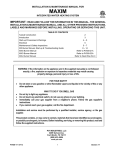
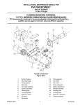
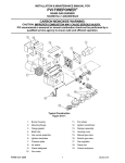
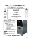
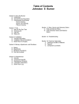
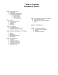
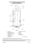
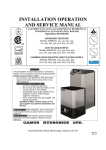
INSTALLATION & MAINTENANCE MANUAL FOR MAXIM INTEGRATED WATER HEATING SYSTEM TABLE OF CONTENTS Start-up Procedures 2 Maintenance & Safety Inspections 3-5 Wiring Diagrams 6,7 Burner 8 Burner Start-up 9-12 Burner Troubleshooting 13.14 MXG Burner Manual Refer to PV500-21A MXO Burner Manual Refer to PV500-22A FOR YOUR SAFETY WHAT TO DO WHEN YOU SMELL GAS: • • • • DO NOT try to light any appliance. DO NOT touch any electrical switch; DO NOT use any phone in your building. IMMEDIATELY call your gas supplier from a phone outside the building. Follow the gas supplier’s instructions. If you cannot reach your gas supplier, CALL THE FIRE DEPARTMENT. FOR YOUR SAFETY DO NOT store or use gasoline or other flammable vapors and liquids in the vicinity of this or any other appliance. FOR YOUR SAFETY WARNING: Improper installation, adjustment, alteration, service, or maintenance can cause injury or property damage. Refer to this manual for assistance, or consult a qualified installer, service agency, or the gas supplier. TYPICAL CONSTRUCTION FIGURE 17-1 1. VENT STACK * 8. HANDHOLE CLEANOUT 2. TEMPERATURE LIMITING DEVICE (set at 200°F) 9. UPPER OPERATING THERMOSTAT (set at 130°F) 3. OPERATING THERMOSTAT (set at 120°F) 10. COLD WATER INLET & RETURN CONNECTION 4. CONTROL SWITCH(es) AND FUSE(s) 11. DRAIN 5. GAS VALVE 12. RELIEF VALVE 6. GAS INLET 13. PRIMARY SAFETY CONTROL 7. BURNER 14. DIFFERENTIAL AIR PROVING SWITCH (* NOT FURNISHED BY PVI) CAUTION: Temperatures higher than 130°F increase the risk of scald injury! IMPORTANT! Clearance to unprotected combustible material must be 8” min. at top, sides and rear, and 24” min. in front. MAXIM PV500-17 05-2000 1 Section 17 START-UP PROCEDURES CAUTION: DO NOT RELIGHT PILOT OR START BURNER WITH COMBUSTION CHAMBER FULL OF GAS OR OIL VAPOR, OR WITH VERY HOT COMBUSTION CHAMBER. 3. 1. Study the burner start-up information included in this manual carefully. 2. Fill the water heater tank with water. Open the relief valve or a nearby hot water faucet to allow air in the tank to escape. Be sure all connections into the tank are tight as leaks at tank fittings will damage the insulation. The top thermostat is a temperature limiting safety device set at 200°F. The thermostats are set at the factory at 130°F on the upper operating thermostat and 120°F on the lower operating thermostat. Adjustment may be made by turning the thermostat dial to the desired temperature. CAUTION: TEMPERATURES HIGHER THAN 130? F INCREASE THE RISK OF SCALD INJURY. CAUTION: CONDUCT THE FOLLOWING GAS TRAIN LEAKAGE TEST BEFORE START-UP, ANNUAL INTERVALS AND PRIOR TO INVESTIGATING THE CAUSE OF ANY REPORTED OCCURRENCES OF DELAYED IGNITION. 1. Using an appropriate bubble detection solution, thoroughly coat all gas train pipe connections. If any bubbles are detected, the leaking connection must be tightened, recoated and rechecked to assure stoppage of the leak. 2. Attach a manometer, to measure gas pressure, at the manual gas shutoff valve located just upstream of the gas train. Adjust gas train inlet pressure to the specified value (e.g. 14 in. W.C.), and tightly close the gas train manual shutoff valve closest to burner. PV500-17 05-2000 3. 2 Reattach the manometer to the gas train manual shutoff valve at the burner and record the measured gas pressure in inches of water column (in W.C.). Measure gas pressure again after 15 minutes. If gas pressure has increased 0.5" W.C. or more, the gas leak must be isolated to one or more of the operating gas valves, for example, a solenoid actuated gas shutoff valve. After any leaking valve is replaced, the reassembled gas train must be leak tested again before start-up is attempted. (NOTE: All gas valves removed because of suspected leakage must be returned to PVI Customer Service for disposition.) Section 17 MAXIM MAINTENANCE AND SAFETY INSPECTIONS 1. Establish a preventive maintenance program to assure a longer water heater life. more fresh water containing scale-forming chemicals is brought into the tank. As the temperature of water increases, the rate of scale deposition will be increased. 2. The tank should be flushed at two- or threemonth intervals depending on water conditions in your location. To flush, turn off electrical disconnect switch to prevent the burner from operating. Open the drain valve and allow water to flow through the tank until it runs clear. Close the drain valve and turn the electrical switch back on. Draining two or three gallons from the bottom of the tank on a weekly basis will also help prevent the accumulation of sediment. Water impurities consist of fine particles of soil or sand which will settle out and form a layer of sediment on the bottom of the tank. 4. The tank will have a handhole for inspection and cleaning. (See Figure 17-1, page 1.) To inspect tank for scale buildup, remove the handhole cover. If scale is present, it can be loosened with a high pressure stream of water. The smaller pieces can be flushed through the drain and the larger pieces removed by hand through the handhole. The frequency of inspections will be determined by the rate of scale buildup. Intervals of 3060 days is recommended. 5. If a firetube leaks for any reason, consult factory for instructions. 3. A scale of lime will normally form during operation and will accumulate on the bottom of the tank. Lime is formed from the natural chemicals in the water which precipitate out during heating cycles. Some water supplies contain more of these chemicals than others and scale buildup will occur more rapidly. Other factors affecting scale buildup are the amount of hot water used and temperature of the water. The more hot water used, the NOTE: Condensate coming from the tubes on a cold start is normal and does not indicate a leaking tube. 6. Regularly inspect the bottom tubesheet. Inspect the SCALEGUARD tubesheet insulator for holes or areas that may have pulled away from tubesheet. Repair or replace as required. CARBON MONOXIDE WARNING: CAUTION: IMPROPER COMBUSTION MAY CAUSE SERIOUS INJURY. PVI recommends a seasonal or annual combustion check-out be performed by a qualified service agency to ensure safe and efficient operation. Periodic Inspection of Operational Components Periodic inspection and check-out of the burner ignition, control system, and fuel valve operation (for tight close-off) should be made. Refer to the burner installation instruction for recommendations. 1. Examine the venting system at least once each year for proper connections, alignment and corrosion. The blower inlet will collect dust from the air during operation. Disconnect the power to the heater and clean the blower wheel when necessary. PV500-17 05-2000 Inspect all parts and make replacements when necessary. Check wiring for loose connections and burned wires. 3 Section 17 MAXIM MAINTENANCE AND SAFETY INSPECTIONS (continued) Periodic Inspection of Operation Components (continued) CAUTION: THE RELIEF VALVE IS A PRIMARY SAFETY DEVICE. 2. 3. heater designs vary, only some of these listed inspections may be appropriate for your particular model. The temperature and pressure relief valve may be checked by slowly lifting the seat lever on top of the valve to determine its condition for safe operation. The openings inside the valve may become restricted by a buildup of scale and become inoperative. If the valve does not open and close properly when tested, it must be replaced. Replace the relief valve with like kind or one meeting the requirements stated on the rating decal located adjacent to the relief valve. 4. A table of periodic safety inspections is an attachment of this manual for ease of reference by the building service technician or licensed equipment operator. Since water PVI strongly recommends the recording of significant events, such as maintenance or repair actions and safety inspections, and encourage the preparation of an event log for this purpose. All recorded events should be dated, fully described, and signed by the individual performing the service, repair, or inspection. (See Table 17-1, page 5 for sample of Inspection Record.) CALL YOUR PVI CUSTOMER SERVICE REPRESENTATIVE IF YOU HAVE ANY QUESTIONS. (1-800-433-5654) Instructions for Taking Water Heater Out of Service Extended shutdown of the appliance and restarting are as follows: C. Tag power switch(es) that fuel is off and tank is empty. A. Turn off all power and fuel supplies. D. Refill tank with water and turn fuel and power switch(es) on to restart. Reset all controls and conduct start-up of the appliance as discussed in the previous pages. B. Drain and flush tank as previously discussed. ELECTRICAL 1. Wiring to the unit should conform to the National Electrical Code or the code legally authorized in your locality. A fused disconnect switch should be used for water heater control. Service wiring connections of 120V, 1 phase, 60 Hz. are located in the enclosure on the water heater. PV500-17 05-2000 NOTE: Use only copper wire of proper sizing for incoming service. Damage resulting from use of aluminum wiring will be excluded from coverage under the warranty of this unit. 4 Section 17 MAINTENANCE & SAFETY INSPECTION REPORT DATE Recommended Inspection Intervals COMBUSTION TANK BURNER ANALYSIS INSPECTION INSPECTION YEARLY 6 MONTHS 6 MONTHS TANK FLUSH TANK FITTING VENT THERMOSTAT & CLEANOUT INSPECTION INSPECTION INSPECTION 3 MONTHS 6 MONTHS YEARLY YEARLY TABLE 17-1 NOTE: Burner Inspection and Combustion Analysis should be done by a factory authorized service person. PV500-17 05-2000 5 Section 17 GAS TRAIN LEAK TEST YEARLY MAXIM AXIAL FLOW GAS BURNER CARBON MONOXIDE WARNING: CAUTION: IMPROPER COMBUSTION MAY CAUSE SERIOUS INJURY. PVI recommends a seasonal or annual combustion check-out be performed by a qualified service agency to ensure safe and efficient operation. TYPICAL CONSTRUCTION FIGURE 17-2 1. FAN HOUSING 9. AIR PROVING SWITCH 2. AIR DAMPER 10. DAMPER ADJUSTMENT KNOB 3. GAS NOZZLE ASSEMBLY 11. MANUAL SHUTOFF VALVES 4. PRESSURE PLATE 12. GAS PRESSURE REGULATOR 5. BLAST TUBE & BURNER HOUSING JUNCTION 13. GAS VALVE 6. IGNITION TRANSFORMER 14. AUXILIARY GAS VALVE 7. IGNITION ELECTRODE 15. MAIN GAS TRAIN 8. FLAME SENSING ROD 16. ELECTRODE CLAMP PV500-17 05-2000 6 Section 17 MAXIM AXIAL FLOW GAS BURNER START-UP (Refer to Figure 17-2, page 6 to identify burner parts) 1. Remove the enclosure panel cover on the water heater or boiler to expose the control circuit. A wiring diagram, included in this packet, will show the controls used in our circuitry. 2. Visually check that all components are intact and no damage has occurred during transit. 3. Check all connections within the control cabinet. A loose connection could cause intermittent shutdowns. 4. 7. With the electrodes exposed, check them for the proper settings as called for in Figure 17-3, page 8. Check for any hairline cracks in the insulators. Should replacement of burner electrodes be required, certain procedures must be followed. In all cases, removal of the electrodes is accomplished by loosening the electrode mounting clamps. Draw the electrodes out of the nozzle assembly through the holes in the pressure plate. 8. Inspect the electrodes for cracked ceramic or loose retaining studs that hold the wire within the ceramic. Select the proper pressure plate hole to place each electrode and insert the electrode through the hole, retaining stud end first. Some burners will use direct spark ignition. They may use a single gas pressure regulator and gas valve or multiple valves and regulators. On a call for heat, the motor starts, the gas primary control is energized, and after a short delay (prepurge) the gas valve(s) opens and ignition should occur. 9. Tighten electrode mounting clamp slightly until electrode ceramics are seated firmly and completely in the mounting bracket without gaps between ceramics and mounting bracket at the bearing faces. NOTE: Do not tamper with or readjust program dipswitch settings. This will cause the control to become inoperable. Damage resulting from tampering will be excluded from coverage under the warranty of this unit. 5. 10. Measure and set electrodes according to Figure 17-3, page 8. After the gaps and setting are complete, fully tighten the electrode mounting clamp. Do not overtighten or the insulation may crack. Remove the flame safeguard control from its base. Check the connections in control mounting base; loose connections can cause nuisance shutdowns. Check the time card or programmer, when applicable, for good connection. 11. Replace nozzle assembly; be sure to connect the flame and spark rod wires before installing nozzle assembly fully into blast tube. Check connectors on the ends of the flame and spark rod wires for good contact. Look for properly stripped wire ends. Be sure connectors are firmly attached to the flame and ignition rod ends. Insulating boots can give a false feeling of proper seating. DO NOT MOVE ELECTRODES. Be careful not to bump electrodes. Check fan wheel for free rotation. NOTE: Always secure gas lines and tag "Out of Service" before servicing burner nozzle or electrodes. 6. Pull the nozzle assembly to check the flame and ignition electrodes. This is done by first disconnecting the gas train by breaking at the unions. Then removing the nozzle assembly which will have the electrodes and pressure plate attached. Disconnect the electrode wires and take care not to damage the insulation on the electrodes. PV500-17 05-2000 12. Reinstall orifices in unions (if required). Reinstall gas nozzle assembly. 7 Section 17 MAXIM AXIAL FLOW GAS BURNER START-UP (continued) PRESSURE PLATE Set up and Tolerances Figure 17-3 13. Connect a test meter to the control for reading the flame response signal. must be monitored during the firing of the burner. Record static pressure; it must not exceed 14" W.C. Pressures above this could cause damage to the diaphragm in the gas valve or pressure regulator. NOTE: Some controls read the flame signal in micro amps and some in volts DC. The TFM or MC120 series control has two terminals marked for reading volts DC. The S89 control uses a micro amp signal for measuring flame strength. For this control, a meter must be hooked in series with the flame rod wire. Disconnect the leadwire at the S89 sensor terminal. Connect the positive lead of the meter to the quick-connect sensor terminal on the S89 and the negative lead to the free end of the sensor leadwire. 15. Burners with pilot; inputs over 400,000 Btu/h (See wiring diagram.) 16. Connect a manometer to the manifold test port at the shutoff valve closest to the burner. Turn off the main gas shutoff valve. Set the air shutter as shown on the tag attached to gas train. This may not be the exact setting you end up with, but it is a good starting point. Turn the unit on using the rocker switch on the side of the control enclosure assembly. If the operating control switches are closed, the burner blower should come on and pre-purge begin. 14. Be sure the tank is filled with water. Once the burner is reassembled, two devices to read pressure, preferably U-tube manometers, will be needed to read gas pressures. Connect one to read the inlet pressure of the burner. This is the pressure measured before all components in the gas train. The manometer must stay connected throughout the testing as the inlet pressure PV500-17 05-2000 If nothing happens, check the control to be sure it is not in the tripped position and reset it by pushing the flame safeguard reset button. The burner should pre-purge for no longer than thirty seconds. 8 Section 17 MAXIM AXIAL FLOW GAS BURNER START-UP (continued) This section pertains to MC120 control only. NOTE: Where low gas pressure is a problem, special arrangements may have been made to fire the burner with reduced pressure. The appliance data decal will reflect this information. When the blower motor starts, the air proving light on the MC-120 should be on. This indicates a positive air flow condition. If the air proving light is not on, turn air proving switch adjustment screw counter-clockwise until the air proving light comes on, then turn screw one turn counter-clockwise. If the gas valves open and close intermittently during normal operation, turn screw one half turn counterclockwise until this condition ceases. This procedure should be followed with every burner. 16. Connect manometer to the manifold test port. Set the air shutter as shown on the tag attached to gas train. This may not be the exact setting you end up with, but it is a good starting point. After purging is complete, terminal 3 energizes the pilot valve and terminal 4 energizes the ignition transformer on the control. The pilot is then established. The VDC reading on the meter should read a steady 14-17 VDC. Each different control will have the required flame response signal stamped on it. This is the minimum for it to properly operate. If the pilot fails to light during the initial period, it is probably due to air in the line. The control will lock out. Wait one minute and push the flame safeguard reset button to restart burner and begin the purge cycle again. Turn the unit on, using the rocker switch on the side of the control enclosure assembly. The burner should come on and ignition occur. If the burner fails to ignite, there may have been air in the line. To reset the control, turn the switch off for 60 seconds (S89 controls only) and it should automatically reset, or push the reset button on the control. If after the appropriate prepurge, ignition does not occur, turn air proving switch adjustment screw counter-clockwise until TFI (try for ignition) occurs. Now in order to more precisely adjust the air failure set point, slowly turn screw clockwise until the burner shuts off. Then turn screw counter-clockwise one turn. If the gas valves open and close intermittently during normal operation, turn screw one half turn counter-clockwise until this condition ceases. Once the flame is established, set the pilot pressure (measured downstream of gas valve) at pressure shown on the tag attached to gas train. Next, open the main gas valve slowly. Set manifold pressure at pressure shown on the tag attached to gas train. Do not screw the adjusting nut of the regulator in past the point where no further increase in manifold pressure is noted. Check the incoming pressure with the burner running. This is recorded as inlet flow pressure. Once the burner fires, set manifold pressure at pressure shown on the tag attached to gas train. There will be a tap on the downstream side of the valve to measure pressure. The manifold pressure must be taken downstream of the gas valve. Check the incoming pressure with the burner running. This recorded flow pressure must be the minimum specified on the heater decal. Our standard flow pressure requirement on these burners is 8" W.C. flow. If the required manifold cannot be reached, check the inlet pressure. It should be a minimum of that shown on the heater decal with the burner running on full input. It is important that the incoming pressure does not fall below these minimums or nuisance control lockouts could occur. PV500-17 05-2000 Direct Spark Ignition - (DSI) Burners - No pilot. (See wiring diagram.) 9 Section 17 MAXIM AXIAL FLOW GAS BURNER START-UP (continued) 17. Check flue gases with a flue analyzer to make final settings of the air shutter. a. The readings need to be taken from a hole in the vent several inches above the heater vent connection, but before draft regulator. b. Insert draft gauge into the 1/4" test opening in the stack. Draft in stack should read -.02" to -.06" W.C. Adjust draft regulator, if installed. c. When water in the tank is above 120? F, insert analyzer or O2 tester in 1/4" test opening and take O2 reading in percentage. d. Gradually close air shutter, taking O2 reading at each adjustment of air shutter until optimum O2 % (4-6%) is reached. If O2 % decreases, open air shutter to last reading where the greatest reading is achieved. i. Make sure the air shutter is locked securely in place. 18. On burners with pilots, recheck pilot to make sure its operation has not deteriorated if adjustments are made to the air shutter. To do this, shut off the main valve, check the flame response signal by cycling the burner through several lightoffs. 19. Check each operating and limit control to be sure they function properly by lowering and raising the temperature setting on each control, causing the burner to cycle on and off. NOTE: During the initial firing of the burner, smoke that is not related to the burner will be emitted from the heater. This is normal during "burn in" and could possibly continue for several hours. 20. Record the following information for future use: e. Insert CO tester in 1/4" test opening and take CO reading. CO should not exceed .03%. A reading greater than .03% indicates lack of air. Open air shutter slightly and take readings until CO is within proper range. Optimum reading is no CO. A. Air shutter position________________ f. E. CO2 reading______________%(8-9%) If air shutter was changed during CO test, take a final O2 reading. B. Manifold gas pressure________"W.C. C. Stack draft_________________"W.C. D. O2 reading_______________%(4-6%) F. CO reading________%(less than .03%) g. Insert CO2 tester in 1/4" test opening; record in percentage. h. Insert stack temperature gauge in 1/4" test opening and read gross stack temperature; maximum gross stack is to be 450°F, minimum net stack is to be 300°F. (NOTE: net temperature is the total stack temperature, less room temperature.) If an excessively high gross stack temperature is recorded, check the flue tubes for turbulators. PV500-17 05-2000 10 G. Stack temperature: Gross _______________________°F. Less ambient__________________°F. Net__________________________°F. H. Combustion efficiency___________% Section 17 MAXIM TROUBLESHOOTING SUGGESTIONS AXIAL FLOW GAS BURNER 1. BURNER FAILS TO START D. Occasional low voltage supply. Have local utility correct. Make certain the burner control circuit transformer (if supplied) is correct for the voltage and power (VAC) being supplied. Defective On/Off switch. Replace switch. A. Control circuit has an open control contact. Check limits, low water cutoff, proof of closure switch and others as applicable. E. Occasional low gas supply pressure. Have local utility correct. B. Bad fuse or switch open on incoming power source. Correct as required. 3. BURNER MOTOR RUNS, BUT PILOT DOES NOT LIGHT C. Flame safeguard control safety switch tripped out. Reset and determine cause for apparent flame failure. A. Gas supply to burner shut off. Make sure all manual gas supply valves are open. Automatic high pressure valve at meter such as "Sentry" type tripped shut due to high gas pressure. Reset valve and correct cause for trip out. D. Loose connections or faulty wiring. Tighten all terminals screws and consult wiring diagram furnished with the burner. B. Pilot solenoid valve not opening. Listen and feel for valve actuation. Solenoid valve not being powered. Check electrical circuitry. Replace coil or entire valve if coil is burned out. E. Flame safeguard control starting circuit blocked due to flame relay being energized. Possible defective scanner or flame rod - replace. Possible defective amplifier - replace. Scanner actually sighting flame due to leaking fuel valve - correct unwanted flame cause. Defective flame safeguard control - replace. C. Defective gas pilot regulator. Replace. D. Gas pressure too high or too low at pilot orifice (if supplied). Check orifice size in gas pilot assembly. Replace if incorrect. Readjust pressure as required. F. Defective blower motor. Check for free rotation of fan wheel. Repair or replace. G. Air proving switch is not properly adjusted. See Section 15, page 11. 2. OCCASIONAL LOCKOUTS APPARENT REASON FOR E. Defective ignition transformer. Replace. Incorrect ignition electrode settings. Readjust as required. NO F. Defective flame safeguard control or plug in purge timing card. Replace as required. A. Gas pilot ignition failure. Check to see that ignition is instant and that flame signal readings are stable and above minimum values. Use a manometer or 0 to 10" W.C. gas pressure gauge to make certain that pressure is as recommended. G. Air flow switch not making circuit. Check out electrically. Defective air flow switchreplace. Air switch negative pressure sensing tube out of position-reposition as necessary. B. Loose or broken wires. Check all wire nut connections and tighten all terminal screw connections in panel and elsewhere as appropriate. 4. BURNER MOTOR RUNS & PILOT LIGHTS, BUT MAIN GAS FLAME IS NOT ESTABLISHED. A. Main shut off or test cock closed. Check to make certain fully open. C. With flame safeguard controls that incorporate the air flow switch in the nonrecycling circuit, ensure that when main flame lights, the air flow switch is not so critically set as to allow occasional momentary opening of the air switch contacts. PV500-17 05-2000 B. Pilot flame signal reading too low to pull in flame safeguard relay. Readjust as required. 11 Section 17 MAXIM C. D. E. F. TROUBLESHOOTING SUGGESTIONS AXIAL FLOW GAS BURNER (continued) C. Gas line obstructed. Check and correct. Defective automatic main or auxiliary gas D. Gas train main and/or lead test cocks not shut off valves. Check electrical circuitry to fully open. Check and correct. valves. Replace valves or correct circuitry as required. E. Gas supply line between gas company Main diaphragm shut off valve opening too regulator and burner inlet too small. Check slowly. Adjust bleed on valve. supply pressure at meter, determine pressure drop and increase line size as required, or raise supply pressure to compensate for small line. Do Defective flame safeguard control or plug on not raise pressure so high that under static (no amplifier. Check and replace as required. flow) conditions the pressure exceeds the maximum allowable pressure to the gas train Main gas pressure regulator atmospheric components on the burner. vent line obstructed. Correct. G. Defective main gas pressure regulator. Replace. Misadjusted main gas pressure regulator. Readjust to meet required operational values. H. Polarity reversed on incoming power. (S89 control only) 5. CARBON MONOXIDE READINGS ON GAS FIRING A. Flame impingement on "cold" heat transfer surfaces caused by excessive firing rate. Reduce firing rate to correct input volume. B. Incorrect gas/air ratios. Readjust burner to correct CO2/O2 levels, eliminated all CO formation. 6. GAS HIGH FIRE INPUT CANNOT BE ACHIEVED A. Gas company pressure regulator or meter operating incorrectly, not allowing required gas pressure at burner train inlet. Contact gas company to correct. F. Burner gas train components sized too small for supply pressure. Increase component size as appropriate or consult factory. G. Automatic gas valve not opening fully due to defective operation. Replace gas valve. H. Orifice (if supplied) too small. Replace with correct size. I. Defective main gas pressure regulator. Replace. J. Incorrect spring in main gas pressure regulator. Replace as required. K. Main gas pressure regulator vent line obstructed. Check and correct. L. Normally open vent valve (if supplied) not closing when automatic gas valves open. Check to see if valve is fully closed when automatic valves are open. Replace vent valve, if not closing fully. B. Gas cock upstream of train inlet not fully open. Check and correct. Additional troubleshooting information can be found in the Flame Safeguard bulletin supplied with the burner. PV500-17 05-2000 12 Section 17