1
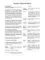
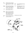
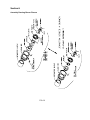
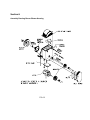
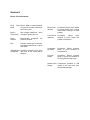
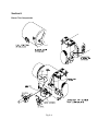
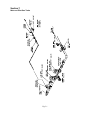
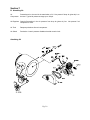
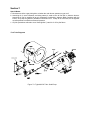
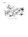
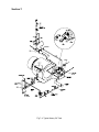
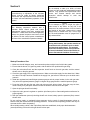
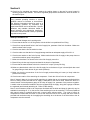
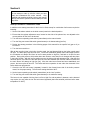
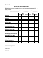
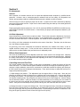
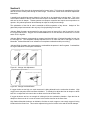
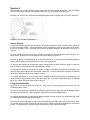
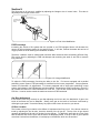
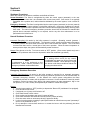
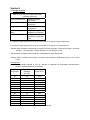
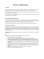
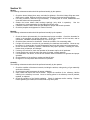
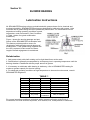
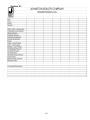
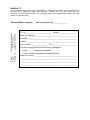
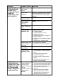
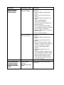
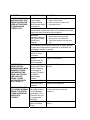
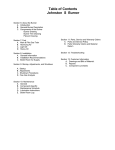
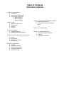
Table of Contents Johnston A Burner Section 6: About the Burner A. Introduction B. General Burner Description C. Components of the Burner a. Burner Drawing b. Blower Drawing c. Plenum Drawing Section 7: Fuel A. Main & Pilot Gas Train B. Atomizing Air C. Light Oil D. Heavy Oil Section 8: Installation A. General Information B. Installation Recommendations Section 9: Startup, Adjustments, and Shutdown A. Startup B. Adjustments C. Shutdown Procedures D. Fuel Analysis Section 10: Maintenance A. General B. Component-Specific C. Maintenance Schedule D. Lubrication Instructions E. Boiler Room Log Section 11: Parts, Service and Warranty Claims A. Parts and Service Policy B. Parts Warranty Claims and Material Return Section 12: Troubleshooting Section 13: Customer Information A. Drawings and Bills of Material B. Reports C. Component cut sheets Contact Information Johnston Boiler Company 300 Pine Street Ferrysburg, MI 49409 SALES Boiler / Burner Pat Baker Phone 616-638-4737 Fax 616-842-1854 Email [email protected] Thom Parker Phone 616-842-5050 ext 314 Fax 616-842-1854 Email [email protected] Deaerators (ancillary) Rick Slater Phone 616-842-5050 ext 336 Fax 616-842-1854 Email [email protected] SERVICE Technical Support Or Field Service Ed Wessel Phone 616-842-5050 ext 311 Fax 616-846-6380 Email [email protected] or [email protected] Spare or Replacement Donna Utzman Phone 616-842-5050 ext 317 Fax 616-846-6380 Email [email protected] PARTS Section 6: About the Burner A. Introduction Thank you for purchasing a series A Burner from Johnston Boiler Company. All Johnston Boiler products are designed and manufactured to give excellent, efficient performance over a long period of time. All items supplied were chosen because of their ability to give high quality performance. Proper operating and maintenance procedures must be followed at all times to insure a high degree of protection and safety. Operation of this equipment should not be considered free from all dangers inherent to operating a steam/hot water vessel with the firing of a combustible fuel. operation. Sheaves, The “A” Burner is indirect drive Belts, Shaft only by design. and Bearings Damper (Includes blades, shafts, bearing and linkage arms, joints, and rods). Throttles the amount of combustion air being produced by the blower wheel and, in turn, the amount of combustion air being delivered to the burner. Inlet Silencer (optional) Insulated extension to reduce air entrance noise. FGR Duct (optional) Tubular duct extending from the boiler flue outlet to the blower inlet. Reduces NOx levels. The operator must be familiar with all components and operations of the burner. Identify and locate each component while reading this manual. Plenum Box Assembly Collects the combustion air and fuel and directs it through the burner. B. General Burner Description Air Pick Up Directs combustion air from the plenum box through the burner internals The operator is solely responsible for properly maintaining the equipment. No amount of documented instruction can take the place of intelligent thinking and consistent safe practices. This manual is not intended to relieve the operator of the responsibility for proper operation. The Johnston Series A Burner is available in gas, oil, and combination gas and oil designs. Special designs are available for burning waste oil, tallow, and low-btu gas. Series A Burners are engineered for firetube and watertube boilers ranging from 50 to 3000 Boiler Horsepower (1,500 to 100,000 lbs Steam per hour). Fuel Selector Shifter Mechanism Mechanically changes the delivery of combustion air to the inside for oil firing and to the outside for gas firing. Also makes and breaks electrical switches to allow the control system to know which fuel the burner is set for. Access Plate Provides for access into burner internals. Also serves as a mounting plate for the pilot, scanner, and oil gun assemblies. All Johnston burners are factory test fired when possible and installed on Johnston boilers. C. Components of the Burner Johnston Series A Burners Fig 6.1 consists of two main assemblies “The Blower Housing” Fig 6.2 and “The Plenum Assembly” Fig 6.2, connected via hinge. Blower Assembly Produces and controls the combustion air flow required for the burner. Blower Motor Drives the blower wheel. Blower Wheel Component that develops positive pressure combustion air for burner Refractory Sleeve Supports combustion and helps establish aerodynamic flow field. The refractory sleeve also protects the boiler tube sheet from high temperature gases and radiation from the flame. Pilot Assembly Provides a flame or high energy spark which is utilized to ignite the fuel at the main burner. Standard electrode setting is 1/8" to 3/16" gap. Scanner Assembly Sensor which ensures that pilot and main flame have been established and are proven during all firing conditions. Either ultraviolet or infrared, depending on application. Air Slide Directs the combustion air within the burner for either gas or oil firing. Oil Gun Assembly Delivers and mixes the required amount of oil and atomizing air (primary air) to the burner, at the point of combustion, for oil firing. Small A series burners have one oil nozzle, while large A series burners have three individual oil nozzles. Main Gas Ring Delivers the required amount of gas to the burner and distributes the gas At the point of combustion. FIG 6.1 Spuds or Plugs Used to establish good mixing of the gas and combustion air at the burner front. Swirlers Inside – Used for oil firing. Controls the mixing of combustion air with the oil at the burner front. Outside – Used for gas firing. Controls the mixing of combustion air with the gas at the burner front. Assembly Drawing of an A Burner Section 6: Assembly Drawing Burner Plenum FIG 6.2 Section 6: Assembly Drawing Burner Blower Housing FIG 6.3 Section 6: Burner Trim Components Firing Motor Rate Electric Motor to rotate jackshaft on signal to increase or decrease burner firing rate. Ignition Transformer High voltage transformer , when energized, ignites pilot fuel. Flame Scanner Electronically recognizes presence of flame. Pilot Normally natural gas or propane. Interrupted small flame to ignite main flame. the Jackshaft and Transfers movement from firing Linkage Set rate motor to fuel valves and air dampers. Blower Door Interlock Permissive- Electric micro switch to prevent blower from running while blower housing is in open position. Fuel Position Interlocks Permissiveelectric micro switches to prove proper fuel position of the burner. Combustion Air Switch Permissive- Electric pressure switch to prove presence of combustion air. Purge Air Switch Permissive- Electric pressure switch to prove the presents of air during burner purge cycle. Grease (zurk) Connections provided to add Fittings grease to the inner and outer blower shaft bearings. Section 6: Burner Trim Components Fig. 6.4 Section 7: Fuel A. Main & Pilot Gas Train Low Gas Pressure Switch Opens under a low gas supply pressure condition. Will not allow the burner to operate under this condition. Pilot Gas Train Safety Shutoff Valves Open to admit gas to the main burner, but only after a pilot has been proven. Electrically actuated and equipped with a proof of closure switch. (If required) Vent Valve Electric normally open valve, closes when energized. (when req’d) Relieves pressure between normally closed valves. Supervisor Shutoff Cock Downstream shutoff cock, between main gas valve and flow control valve. Manually opens and closes the gas supply to the main burner. Manual Manual valve that controls the Shutoff Valve gas supply to the pilot train. Pressure Regulator Reduces the incoming gas supply pressure to meet the lower pressure requirements of the pilot. Shutoff Valves Electric normally closed valve(s), when energized, open to admit gas to the pilot. (One or two, depending on insurance/code requirements) Pressure Gauge Vent Valve Indicates the regulated supply pressure to the assembly. gas pilot Electric normally open valve, closes when energized. (when req’d) Relieves pressure between normally closed valves. Main Gas Train Main Shutoff Cock Upstream shutoff cock at entrance to the main gas train. Manual valve that controls the gas supply to the train. Supply Pressure Regulator Reduces the incoming supply pressure to meet the lower pressure requirements of the main burner and eliminates any fluctuation in the gas supply pressure. Regulated Pressure Gauge Indicates the regulated gas pressure to the main gas train. Control Valve Controls the amount of regulated gas supply pressure to the main burner. Valve is controlled by the burner management system. Burner Pressure Gauge Indicates the gas supply pressure to the main burner. High Gas Pressure Switch PermissiveContacts open under a high gas supply pressure condition. Will not allow the burner to operate in high gas pressure conditions. Note: Gas supply for pilot should be upstream of main shutoff cock. (Certain main gas supply regulators require this connection to be downstream. Check piping schematics for correct connection). Section 7: Main and Pilot Gas Trains Fig. 7.1 Section 7: B. Atomizing Air Air Compressor Pressurizes air to be used in the atomization of oil. Not present if shop air (plant air) is to be used. Typical air pressures range up to 100 psi. Air Regulator Controls fluctuations in the air pressure from shop air (plant air) line. Not present if air compressor is used. Air Tank Dampens pulsations from air compressor. Air Switch Permissive- Low air pressure disables electrical control circuit. Atomizing Air Fig. 7.2 Section 7: D. Heavy Oil Additional equipment provided for heavy oils. C. Light Oil Inlet Strainer Filters out any foreign matter in the fuel oil supply. Oil Pump Increases the pressure of the fuel oil supply to the required pressure. See oil pump manual for exact inlet pressure ratings. Caution: Some pumps will leak through shaft seal if rated inlet pressure is exceeded. Oil Regulator A back supply pressure regulator that maintains constant oil pressure to the flow control valve. Excess oil is recirculated back to a tank or the pump inlet. The set pressure is a function of firing rate and required nozzle pressure. Typical supply pressures to nozzles are 40-80 psig for Delevan nozzles and 50100 psig for Monarch nozzles. (Not always supplied, may be integral to pump). Low Oil Pressure Switch Opens under a low oil supply pressure condition. Will not allow the burner to operate under this condition. Safety Shutoff Open to admit oil to the main Valves burner, but only after a pilot has been proven. Electrically actuated. If the flame signal drops off, the oil valve will shut to insure proper, safe combustion (May be equipped with a proof of closure switch depending on insurance/code requirements). Flow Control Valve Throttles the amount of regulated fuel oil supply to the main burner from low to high fire. Fuel Oil Preheaters Electric and/or Steam. Used to heat heavy (No. 4 thru No. 6) fuel oils, tallow, and waste oil. An electric preheater is a thermostatically controlled, low watt density preheater, for cold oil starting. A permissive low oil temperature switch is built in to prevent starting on a low temperature condition. A steam preheater is an indirect steam heater with a capacity to heat the fuel oil from approximately 100°F to 230°F. A steam preheater is used to heat heavy oils once the boiler reaches its normal operating steam pressure. When used in combination fuel burners, the electric heater is used as a trim heater, maintaining a constant supply temperature. Heat Trace Oil Solenoid Valve (Heavy Oil Only) Permits the circulation of hot oil in the fuel oil supply system during boiler/burner off periods. This is done to keep the oil in the line hot for good atomization and flow during burner operation. Temperature Regulates steam flow to heater Control Valve on the basis of oil temperature entering the heater. Temperature Switch Permissive- switch interrupts control circuit on high temperature of oil. Steam Regulator Supplied when boiler operating pressure exceeds 150 psig. Steam Trap Collects and discharge condensate from steam heater. Section 7: Special Notes: a. Most burners utilize a gas pilot ignition, whether the main burner operates on gas or oil. b. Atomizing air (in some instances, atomizing steam) is used to burn all fuel oils in Johnston burners. Atomizing air can be supplied by an air compressor furnished by Johnston Boiler Company with the burner, or by shop air (plant air) available in the boiler room. If shop air is to be used, an air regulator must be present to maintain constant air pressure. c. Oil pilot (sometimes referred to as a “diesel ignition”) uses No. 2 oil for pilot flame. Fuel Train Diagrams Figure 7.3: Typical #2 Oil Train Small Pump Section 7: Figure 7.3: Typical #2 Oil Train Large Pump Section 7: Fig 7.4 Typical Heavy Oil Train Section 8: Field Installation (If not factory installed) A. General The following are general recommendations for assembly and installation of a Johnston A style burner. Refer to Section 6 to familiarize yourself with parts and terminology. It is strongly recommended that a qualified field service technician familiar with Johnston products be present to supervise or do the work. These burners will be heavy and unlikely to be lifted by hand. You will need appropriate lifting equipment such as fork lifts, cranes or cherry pickers to position the burner in place. Local Code requirements must also be followed. These legal requirements take precedence over information found in this manual. B. Installation Recommendations Your Johnston A style burner will be shipped in multiple pieces and will need to be field assembled at installation. If your burner arrives fully pre-assembled, it will need to be partially broken down prior to installation. The following steps are for reference only and may be altered, skipped or rearranged on the basis of field advice for your application. 1) Break down burner into at least two pieces; A. The plenum assembly; B. The Blower assembly. This requires removal of hinge pins and all interconnecting wire, linkage, tubing and pipe. 2) Install gasket on plenum mounting flange, if shipped loose. 3) Insert plenum assembly into furnace opening, plumb and level and attach nuts and washers. 4) If excess space between the firing tube and furnace opening exists, fill the gap with a refractory type of insulation blanket, block or mud. 5) Attach blower housing to plenum assembly via hinge pins. 6) Connect or install all other devices as required for your application and purchase. 7) Electrical supply lines should be properly installed to the burner. It is recommended that fuel supply lines be properly valved, so the supply lines to the burner can be shut off when it is not in use or when preventive maintenance or repairs to the burner are being made. A “dirt trap” should be installed in the gas supply line, just prior to entering the main gas train of the burner. A means to disconnect and lockout the power supply to the burner control panel should also be provided. Installation of burner fuel and electrical power supply piping and lines should be checked, so as not to interfere with operation of any component part of the burner, or interfere with the ability to perform preventive maintenance or make repair. Special attention should be given to making sure that no piping or lines interfere with chamber doors, hatches, or removable components. C. Boiler Room Air Supply The starting point in any combustion system is the supply of fresh air. To avoid serious problems, the boiler must have an adequate supply of fresh air and a supply system that does not affect the boiler operation. An adequate, proper and consistent supply of fresh air must be supplied into the boiler room for burner combustion air. A rule of thumb is to provide four to six square inches of open, unrestricted area for every boiler horsepower. Example: For a 75 HP boiler, 300 to 450 square inches of open unrestricted area are recommended. How much air is required? In general, the following formulas have been developed to determine the amount of combustion air required for any boiler room with a package firetube boiler firing gas or oil fuels: Section 8: ft 3 min⋅ HP ft 3 Ventilation _ Air = HP ⋅ 2 min⋅ HP ft 3 Total _ Air _ Re' q = HP ⋅ 10 min⋅ HP Combustion _ Air = HP ⋅ 8 HP refers to the total maximum boiler horsepower in the boiler room. These calculations are adequate for installations up to 1000 feet above sea level. For any installation above 1000 fasl, add 3% air for each 1000 fasl. What size of opening to the outside is required? The size of the fresh air inlet openings and their location are very important. There should be a minimum of two permanent air supply openings in the walls of the boiler room. Whenever possible, they should be at opposite sides of the boiler room and no higher than 7 feet above the floor. This will promote mixing with the air already in the boiler room, proper cooling of the boilers, and tempering of potentially colder outside air prior to its entering the burner for combustion. The air inlets should be provided with some type of weather protection, but should never be covered with a fine mesh wire screen. This type of covering results in poor air flow and is subject to clogging by dust, dirt, paper, and other small items. To determine the net free open area required for an opening, divide the total air required (in cubic feet per minute) by the allowable velocity at the opening, from the table below. Acceptable Air Velocities in Boiler Room 0-7 ft above floor 250 feet per minute Above 7 ft above floor 500 feet per minute ***The minimum opening to the outside should be one square foot*** Air Ducting In some applications, the boiler room is located in a building such that it has no outside walls. Many of these applications do not have sufficient excess makeup air in the factory to allow for combustion air requirements. In these cases, there are two possible solutions: 1. Ducting fresh air into the boiler room. Where this is required, the general rules for the size of the wall opening can be used to determine the size of the ducting and wall opening in the boiler room. In addition, the pressure drop through the duct must never exceed 0.05” w.c. 2. Ducting fresh air directly into the boiler. This method of air supply should be avoided whenever possible. The disadvantages of this type of system far exceed any perceived advantages. If used, the ducting becomes a part of the boiler system and can affect the stability of combustion due to varying weather conditions, wind direction and velocity, humidity, and temperature. Changes in temperature can lead to massive CO production, soot formation, and unstable, unsafe combustion. If direct ducting is to be used, we suggest the following steps be followed: 1. Each boiler has its own, completely separate, fresh air ducting and exhaust stack to minimize combustion problems. 2. Boiler directly connected to fresh outside air ducts must be checked for proper combustion adjustment and operation every three months by a certified package firetube boiler specialist. 3. The duct work supplying the fresh air to the boiler must be sized so that it has a maximum pressure drop of 0.05” w.c. at maximum flow. Section 8: 4. The fresh air supply should have an electric, hot water, or steam heater to temper cold outside air to at least 50 deg F. 5. If the application is utilizing a low emission with flue gas recirculation, do not use direct ducted outside air. The potential problems associated with a standard burner are intensified with a low emission burner. Section 9: Startup, Adjustments, and Shutdown A. Startup General Startup Information When possible, Johnston burners are factory test fired to ensure that components and systems are functional. All burners supplied on Johnston boilers are test fired as units, to as close to the minimum and maximum firing rates as practical. The fuel air ratio is adjusted as much as possible with the factory conditions. Because each field application is unique due to flue stack configurations, fuel composition variations, elevation, and other variables, the final burner setup and calibration must be conducted after system installation by a qualified Burner Service Technician. Contact your Johnston Boiler Representative or the Johnston Boiler factory service department for scheduling and rates of factory authorized commissioning assistance. Burners supplied as stand alone items will not be fire tested. Where the word “boiler” is used, it will be synonymous with chamber or other device to which the burner is applied. Pre-Startup Checks: Boiler or Applicable Chamber Note: If your Johnston burner is to be installed on an apparatus not made by Johnston Boiler Company, follow the startup procedure given by the manufacturer of the product. The boiler/chamber is properly installed on a concrete pad, grouted and is level. The flue stack has been installed. A rain cap has been installed if directly connected to the flue gas outlet. The boiler/chamber’s piping, blowoff, blowdown, and feedwater systems have all been installed and connected according to the manufacturer’s instructions. The boiler/chamber’s doors and access openings are fully accessible. NOTE: Each Johnston Burner is shipped with an order specification sheet, bills of material, piping diagram, wiring diagram, and other reference materials specific to this job. A thorough understanding of, and familiarity with, these documents is required prior to systems installation, commissioning, operation or trouble shooting. Pre-Startup Checks: Burner The electrical power supply has been run to the control panel. A disconnect has been installed at the control panel, just before the power supply enters the control panel. If the control panel was supplied by others, ensure that it is wired to match the wiring diagrams that came with your burner. All motor rotations have been checked (blower, oil pump, air compressor) against the direction of rotation labeled on the motor. Due to job-specific differences in motor setup, proper motor rotation is labeled by the factory using arrows. There is nothing about the installation that will no longer allow the burner and fuel train(s) to operate properly and be adjusted, as may be necessary. Fuel supply pressures match the specification sheet. Continuity and electrical check of any wiring that was required into the control panel. For oil firing, fuel oil has been circulated and strainers are empty and clean. Section 9: WARNING: Commissioning or adjustment of the Johnston Burner must be made by factory authorized technicians and experienced service technicians to ensure safe and satisfactory operation of the system. NOTE: The following sequences assume that a Johnston Boiler control panel and burner management system have been supplied with the burner. If these items have been supplied by others, the general sequence and intent will be as follows, but the control system manufacturer will have to be consulted for operational details. WARNING: Do not attempt to start up a boiler or burner unless you have read and understand this entire manual. Only qualified and experienced boiler, burner, and controls start-up and service personnel should attempt to start any boiler/burner. NOTE: Do not attempt to light, or re-light, the pilot or main burner of any boiler, on any fuel, if the presence of an excess amount of fuel is noted in the fireside of the boiler, whether this is noted though smell, or visible to the eye. Prior to light off, the boiler/chamber must be purged free of any unburned fuel. CAUTION: During initial startup, the operator must be on constant alert for conditions such as leaks and electrical malfunctions. The operator should be constantly aware of the positions of manual shutdown valves and switches to ensure fast manual shutdown if necessary. Startup Procedure: Gas 1. Make sure that all linkages, arms, and connection points are tight in the fuel/air ratio system. 2. Ensure that the burner is in gas firing mode, with the shifter lever positioned for gas firing. 3. Close the main shutoff cock and the supervisor shutoff cock on the main gas train, and the manual shutoff cock on the pilot gas train. 4. Check the gas supply for the required pressure. Make sure that the supply line has been bled. Make sure that a “dirt trap” has been installed in the supply line, just before it connects up to the boiler main gas train. 5. Install the regulated and manifold gas pressure gauges at their proper location in the main gas train. Very often the regulated pressure gauge is a higher range gauge than the manifold pressure gauge. 6. Purge the boiler with the pilot gas valve and main gas train valves closed. Once the purge is done, check visually for a pilot spark. Make sure that the scanner does not sense the spark. 7. Open the pilot gas shutoff cock slowly. 8. Adjust the main gas train regulator to optimize pilot flame (refer to flame safeguard manufacturer for proper signals). 9. With the downstream (second) checking shutoff cock closed, slowly open the upstream (first) manual shutoff valve. Do not confuse supply or regulated lockup pressures (as the result of closed downstream valves or shutoff cocks) with continuous flow operating pressures. Continuous flow operating pressure will only be accurate when the boiler is operating. When initially starting a boiler, after a pilot flame has been established, slowly open the downstream (second) checking cock as the main gas shutoff valves open. Section 9: 10. Check low fire regulated gas pressure against the reading shown on the test fire report located in following pages of this manual. The low fire regulated gas pressure should be the same as shown on the test fire report. CAUTION: Every potential operating situation or system condition cannot be foreseen or documented. The following instructions should be used as a commissioning guideline by competent and experienced burner service technicians. Specific situations may mandate deviations based on sound judgment and engineering experience. Consult the Johnston Burner factory if questions or problems are present. Startup Procedure: Oil 1. Check that all linkages are in working order. 2. Ensure that the burner is in oil firing mode, with the shifter lever positioned for oil firing. 3. Check for a manual shutoff valve in the fuel oil supply line, upstream of the fuel oil strainer. Make sure that this shutoff valve is open. 4. Check to see that the fuel oil strainer is clean. 5. Check to make sure that the fuel oil supply/storage tank has an adequate supply of fuel oil in it. 6. Check motor rotation on the fuel oil pump. Make certain that the fuel oil supply to the pump does not exceed the maximum pump inlet pressure. 7. Make sure that there is no shutoff valve in the fuel oil supply return line. 8. Bleed off any air that may have accumulated in the electric oil preheater. 9. Ensure that the manual shutoff valve in the “tracer line” is open. (Heavy Oil Only) 10. Make sure that the drain valve in the fuel oil supply line to the burner oil gun is closed (drain also used for gauge fitting to check burner oil gun nozzle pressure). 11. Make sure that the connections of the fuel oil supply and atomizing air hoses (or lines) inside the plenum box are tight. 12. Check motor rotation of the atomizing air compressor. Check the oil level in the air compressor. Note: If shop air (plant air) is to be used for atomizing air (rather than an air compressor supplied with the burner or boiler), make sure that the air supply is adequate for the burner need. Make sure there is a manual shutoff cock and pressure gauge in the shop air supply line, upstream of the pressure regulator. A needle valve must also be installed to trim the regulated shop air supply, along with a gauge to indicate the regulated (and trimmed) atomizing air. Refer to JBC drawing Note: In some instances, both an air compressor furnished with the boiler and shop air (plant air) may be available for atomizing air. If so, the source of the atomizing air must be controlled. This is accomplished with manual valves or solenoid valves and a control panel selector switch. The motor of some air compressors furnished with the boiler or burner also drives the burner fuel oil pump and motor must be provided and used when shop air is supplying the atomizing air to the burner or the drive belts to the air compressor must be removed. Section 9: WARNING: Do not attempt to start up a boiler unless you have read and understand this entire manual. Only qualified and experienced boiler, burner, and controls start-up and service personnel should attempt to start any boiler. Startup Procedure: Combination Fuels In addition to the startup procedure for the fuel to be fired, startup for combination fuel burners require the following: 1. Set the fuel selector switch on the boiler control panel to the desired position. 2. Ensure that the register adjustment arms, located on the side of the plenum box, are adjusted to the correct position for the fuel to be burned. 3. Turn the burner operating mode switch (manual/auto) to the manual mode. 4. Turn the firing rate control dial switch (potentiometer) to its lowest setting (low fire). 5. Review the startup procedure in the following pages of this manual for the specific fuel (gas or oil) to be burned. 6. Turn the burner switch on. With all the recycling limits in the boiler circuitry made, the load demand light on the boiler control panel will light. The boiler pre-purge will now occur. The burner modulation (MOD) motor and linkage will drive the combustion air damper and from its low fire start position to high fire, and back to its low fire start position. During this process, which takes about two minutes, more than four air changes will take place in the boiler fireside. With the low fire position proven, the burner pilot will attempt to light. After the pilot has been proven, the main fuel valve will open, the vent valve between the main fuel valves will close and the main burner will attempt to light (for gas). After the main burner flame has been established, and proven, the burner pilot will shut off. The boiler and burner operation is now under the command of the boiler and burner programmer. 7. Check the low fire hold control (aquastat), located in the forward lower side of the boiler pressure vessel, for the proper setting. The minimum setting should be 180°F. 8. Set the burner operating mode switch (manual/auto) to the “auto” position. 9. Turn the firing rate control dial switch (potentiometer) to its maximum setting. The burner is now capable of driving from low fire to high fire, and anywhere in between, as the demand may require, but only after the low fire hold control (aquastat) has been satisfied (minimum boiler water temperature of 180°F). Section 9: STARTUP / SERVICE REPORT The following document should be completed by an authorized service technician at startup and after any adjustments are made. A copy of this document must be submitted to Johnston Boiler Company to validate the warranty. Model Number_______________________ Serial Number ____________ Startup Date ____________ Gas Low Fire Stack %O2 Stack CO2 PPM Stack %CO2 Stack NOx PPM Firing Rate (CFH/GPH) Main Flame Signal % Combustion Efficiency Blower Wheel Inlet Pressure (“WC) Plenum Box Pressure (“WC) Rear Combustion Chamber Pressure (“WC) Stack Outlet Pressure (“WC) Fuel Supply Pressure Before Main Regulator (psi) Regulated Fuel Pressure (After Main Regulator) (psi) Manifold Gas Pressure (“WC) Oil Pressure at Nozzles (psi) Atomizing Air Pressure at Nozzles (psi) Ambient Temperature (°F) Stack Temperature (°F) __________________________ Service Technician Signature __________________________ Printed Name __________ Date Mid Fire Oil High Fire Low Fire Mid Fire High Fire Section 9: B. Adjustments General When possible, all Johnston burners are fire tested and adjusted before shipment by qualified burner personnel. However, due to combustion-specific variations such as fuel quality, air composition and density, and operating conditions, additional adjustments at the jobsite are often necessary. The fine tuning of a burner requires a proper fuel air ratio. A proper fuel air ratio is achieved by adjusting both the air flow and the fuel flow. Proper fuel air ratio is tested using the make-up of the stack gases and the stack temperature. Proper stack gases should contain from 3 to 3.5% O2, less than 50PPM CO (90PPM for lo-NOX burners), and 30PPM or less NOX for lo-NOX burners. Consult factory for proper stack temperature based on your boiler model. Air Slide Adjustment Larger horsepower A Series burners contain air slides. The air slide controls the distribution of air that is delivered to the outside and the inside of the flame. In the forward position, the outside air inlet is closed, so all air is forced to the inside. In the back position, the outside air inlet is completely open. For oil firing, all of the combustion air should be at the center of the flame. Therefore, the air slide must be in the forward (closed) position. For gas firing, most of the combustion air should be delivered to the outside of the flame, so the air register should be mostly open. To fine tune the burner, start with the air slide completely back (open) and move the air slide forward slowly until the burner is adequately tuned. Diffuser Vane Adjustment The vanes of the diffuser(s) can be adjusted to allow the correct amount of air through them. Adjusting the vanes will also adjust the amount of swirl inflected upon the air that travels through them. Adjusting the vanes of the diffuser is a finer adjustment than adjusting the air slide, so it should be performed after the air slide has been properly adjusted. Controlling Amount of Fuel Flow The control systems used when setting up the burner are designed to control the amount of fuel that enters the burner. The most common system installed on boilers is the single point positioning system. It employs a single modulation motor that is connected to a shaft that controls the opening and closing of the fuel control valve(s) and air damper simultaneously. There are three ways to adjust the fuel flow on a single point positioning system: 1) Adjust linkage joint position. This adjustment has the largest effect on firing rates. Move the joint between the linkage rod and the linkage arm to a different hole on the linkage arm. Doing so will change the linkage arm’s radius. By moving the joint towards the pivot of the linkage arm, a driven linkage arm will increase rotation greatly. By moving the joint away from the pivot of the linkage arm, a driven linkage arm will decrease rotation. If the joint location is moved towards the pivot of a driving arm, the rotation of the driving arm will not be affected, but the linkage rod will move slower, causing the driven arm to rotate slower. If the joint is moved away from the pivot of a driving arm, the driven arm will move quicker. 2) Change the stroke or length of the linkage rods. This will change how fast or how slow the modulating firing rate motor changes the fuel or air settings. By increasing the amount of “dead travel” that a linkage arm must go through, the firing rate will be slowed down. By decreasing the amount of “dead travel”, the firing rate is sped up, and the burner will travel to high fire more quickly. Section 9: 3) Adjust the fuel flow through the characterized fuel control valve. This is done by matching the fuel flow with the air flow at each point through its travel range. Consult fuel control valve manual for adjustment instructions. A parallel point positioning system allows the fuel and air to be introduced at varying rates. This is the more modern method of fuel air ratio control and requires a modulation motor for each fuel control valve and one for the air damper. Theses systems are computer controlled and require some experience to operate. Only trained personnel should attempt to adjust or modify these settings. The optimization of the fuel air ratio is essential to efficient operation of any burner. Analysis of flue gases with proper instruments is the only way of truly optimizing fuel air ratio. Johnston Boiler Company recommends flue gas oxygen levels of around 8% in low fire and 3-4% in high fire for gas fired burners. Oxygen level recommendations for oil fired burners are around 6% in low fire and 4-4.5% in high fire. Johnston Boiler Company recommends no greater level than 200 ppm of Carbon Monoxide for both low fire and high fire. The acceptable industry standard level is no more than 200 to 400 ppm of Carbon Monoxide. Carbon Monoxide is an indication of incomplete combustion and/or poor mixing. Johnston Boiler Company also recommends no combustibles be present in the flue gases. Combustibles are a good indication of incomplete combustion. Joint farther from pivot Joint closer to pivot e ag m Ar Linkage Rod k Lin Figure 9.1: Linkage Joint Adjustment Large Rotational Motion = Small Linear Rod Motion Small Rotational Motion = Large Linear Rod Motion θ θ Figure 9.2: Linkage Arm Modification If oxygen levels are too high, too much excess air is being allowed into the combustion chamber. High oxygen levels may also cause loud flame vibrations. To remedy this, adjust the inlet air damper to allow less air in or adjust the fuel control valve to allow more fuel to the flame front. If oxygen levels are too low, not enough air is being let into the combustion chamber. Open the inlet air damper to allow more air in or tune the control valve to allow less fuel to the flame front. High Carbon Monoxide levels are an indication of either too much oxygen or not enough oxygen is being introduced to the flame front. This must be adjusted using the fuel control valve and the inlet air damper. Section 9: With gas burners, at high fire, with a proper fuel air ratio, the flame should appear blue. With a Johnston Lo-NOx FGR system, the flame should appear dark blue or even a purple color at high fire. At high fire on an oil burner, the flame should appear bright yellow if a proper fuel to air ratio is achieved. Figure 9.3: Inlet Air Damper Adjustment Inlet Air Damper On burners equipped with an inlet air damper, the airflow through the burner is limited by the position of the inlet air damper blades. If the air blades are too far closed during high fire, the burner will be underfired even if properly tuned. A general rule is that the air blades should be at least 80% open when on high fire. On most Johnston burners, the inlet air damper is between the silencer and the blower housing. On some models, however, the inlet air damper is above the silencer (Figure 5.3). The inlet air damper controls the amount of air let into the blower. For burners with a parallel positioning system, the air damper is controlled directly by the burner programmer. For burners with a single point positioning system, linkages from the MOD motor are used to control the inlet air damper. These linkages may be adjusted as follows: To decrease the amount of air let into the burner, increase or decrease the length of the linkage rod to obtain a larger angle between the rod and the linkage arm. This will decrease the amount of rotational travel for an equal amount of travel made by the arm. To increase the amount of air let into the burner, increase or decrease the length of the linkage rod to obtain a smaller angle between the rod and the linkage arm. This will increase the amount of rotational travel for an equal amount of travel made by the arm. Firing Rate Modification Firing rate is the rate at which fuel is burned. Firing rate is controlled on gas and oil burners by the modulating control valves. For burners equipped with a parallel point positioning control system, firing rate can be adjusted directly from the boiler programmer. See programmer manual for instructions on adjustments. For burners equipped with a single point positioning system, as seen in figure 4.2, adjustments are made by modifying the linkages from the MOD motor. The firing rate can be adjusted on gas burners by adjusting the linkage connection to the control valve. To increase the firing rate, lengthen the connecting rod to create a great angle between the rod and the linkage. To decrease the firing rate, shorten the connecting rod to decrease the angle. Section 9: The firing rate on oil burners is modified by adjusting the linkage to the oil control valve. This valve is adjusted just like the gas control valve. Less Dead Travel: Burner Fires More Quickly More Dead Travel: Burner Fires More Slowly Figure 9.4: Fuel Valve Modification FGR Percentage Increasing the amount of flue gases that are recycled on an FGR equipped burner will decrease the amount of NOx emissions present in the stack flue gas. It will also, however decrease the amount of oxygen present in the air entering the combustion chamber. Therefore, a balance must be reached that minimizes NOx emissions while still allowing efficient firing. This can be done by adjusting the FGR inlet damper and monitoring the stack O2 and CO to measure firing efficiency. θ θ Figure 9.5: Linkage Modification To adjust the FGR percentage, first bring the boiler to low fire. For burners equipped with a parallel positioning control system, FGR percentage is modified from the burner programmer. See programmer manual for information on adjustments. For burners equipped with a single point positioning control system, the linkages to the FGR damper must be modified. Increasing the angle θ as shown n figure 5.5 will increase the amount of FGR introduced off of low fire. There is also a fixed shutoff damper in the FGR line. It can be used to control the maximum amount of FGR introduced. Gas Ring Adjustment If the burner is not firing correctly on gas after adjusting the fuel air ratio, the distribution of gas to the inside of the flame may not be adequate. Getting more gas to the inside of the flame is achieved by orifacing the gas spuds. Consult the factory for proper orifice sizes to be used on your burner. Oil Gun Location The location of the oil gun relative to the diffuser is important when firing on oil. If the burner cannot be tuned by adjusting the fuel air ratio, check the location of the oil gun tip. The tip of the oil gun should generally be between 0.00 and 2.00 inches from the diffuser. To adjust this, start with the oil gun flush with the diffuser and move it back until the burner is adequately tuned. If the tip of the oil gun is placed more than 2 inches from the diffuser, oil could spray on the diffuser, which is to be avoided. Section 9: C. Shutdown Shutdown Procedures Within this manual, two shutdown conditions are defined as follows: Normal Shutdown: The flame is extinguished by either the control system (automatic) or the user (manual) with the intent that it be restarted within a short time period. Such action is not typically associated with a problem and, unless otherwise indicated by the control system, is not a cause for alarm. Emergency Shutdown: The flame is extinguished by the control system (automatic) or the user (manual) and is the result of a system problem or equipment malfunction. Under such conditions, the burner may not be restarted until the problem has been corrected and the appropriate safety device(s) have been reset. The manual emergency shutdown procedure should also be followed for extended idle periods where automatic restarting is not required, and at any time that maintenance is to be performed on the boiler/burner. Normal Shutdown Procedure Automatic (Recycling): No action by the boiler operator is required. Operating controls (pressure / temperature sensors) open automatically. The operating control senses the boiler water temperature or steam pressure and shuts down the burner when it has reached the setpoint. This is the most common shut down and is a normal part of the burner operation. When the water temperature or steam pressure drops, the system will automatically restart the burner. Manual: Drive burner to low fire. Turn burner switch to “OFF” position. (Some control panels may have a “Burner Off” pushbutton which must be depressed, rather than a selector type switch) Note: If maintenance is to be performed on the boiler/burner, follow manual procedure for emergency shutdown as described below. Warning: If a starting failure occurs for any reason, combustible fuel gases may fill the furnace and combustion chamber. Never attempt to relight the burner under these conditions without first purging the unburned fuel. Emergency Shutdown Procedure Automatic (Non-Recycling): No action by the boiler operator is required for an automatic emergency shutdown to occur; however the manual emergency shutdown procedure must be followed after an automatic emergency shutdown. In this instance the control system extinguishes the flame automatically and will not restart until the problem is corrected. Such a shutdown is caused by unsafe conditions, such as low water, flame failure, high steam pressure or water temperature, high or low fuel pressure, etc., and is usually accompanied by an audible or visible alarm signal. Manual: 1. Turn the burner switch to “OFF” position (or depress the “Burner Off” pushbutton if so equipped). 2. Close all manual fuel valves. 3. If equipped, turn oil pump on/off switch to off. 4. Close main blowoff or drain valves. 5. Close continuous blowdown stop valve if present at facility. 6. Close main feedwater and chemical feed inlet valves if present at facility. 7. Close hot water valves or steam stop valve(s) if present at facility. 8. Lock out incoming power according to plant specifications at main disconnect panel (necessary if work is to be performed on unit). 9. Do not attempt to reverse these actions or to restart the burner until the problem(s) has been identified and corrected. Section 9: D. Flue gas analysis: Boiler flue gas analysis is used to determine combustion efficiency. Carbon Dioxide (CO2) Carbon Monoxide (CO) Oxygen (O2) Oxides of Nitrogen (NOx) Combustibles Indicates complete combustion Indicates incomplete combustion Indicates the presence of excess air A product of high temperature combustion Material that burns when exposed to oxygen and heat It is typical to target oxygen levels of 8% in low fire and 3% in high fire for gas fired burners. It is typical to target oxygen levels of 6% in low fire and 4% in high fire for oil fired burners. Johnston Boiler Company recommends no greater level than 200 ppm of Carbon Monoxide in its burner operation. The acceptable “Industry Standard” level is 400 ppm or less. Johnston Boiler Company recommends zero combustibles for a gas fired burner. Johnston Boiler Company recommends a maximum #2 Smokespot (Ringelmann Chart) in its oil fired burner. Air Properties: For a burner originally adjusted to 15% air, changes in combustion air temperature and barometric pressure cause the following in excess air: Air Temperature Barometric Pressure (In. HG) Resulting Excess Air %* 40 29 25.5 60 29 20.2 80 29 15.0 100 29 9.6 120 29 1.1 80 27 7.0 80 28 11.0 80 29 15.0 80 30 19.0 40 31 34.5 60 30 25.0 80 29 15.0 100 28 5.0 120 27 -5.5 * Expressed as a percent of the Stoichiometric air required. Section 10: Maintenance A. General A good maintenance program is essential to the lasting operation of your Johnston burner. Properly maintaining the burner will reduce unnecessary downtime, lower repair costs, and increase safety. All electronic and mechanical systems require periodic maintenance. Automatic features do not relieve the operator from maintenance duties. Any unusual noise, improper gauge measurement, or leak can be a sign of a developing problem, and should be taken care of immediately. B. Component-Specific Maintenance Most of the components and systems of your Johnston burner require little maintenance other than regular inspection. Cleanliness is essential to the inspection of the burner. Keep the exterior free of dust. Keep the controls clean. Clean dust and dirt from the motor starters and relay contacts. See individual component manuals for more information on specific component maintenance issues. C. Maintenance Schedule Johnston Boiler Company recommends the following maintenance schedule for the upkeep of your Johnston burner. Any omission form this schedule could cause the Warranty to be voided. Only qualified and experienced boiler, burner, and control personnel should attempt any maintenance and/or repair on any boiler/burner. Be sure you have read and understood this entire manual before attempting maintenance or repair. This maintenance schedule assumes a Johnston burner. Refer to your boiler manual for trim and boiler maintenance. Daily: The following maintenance tasks should be performed daily by the operator: 1. Check boiler manual for all items pertaining. 2. Check over the boiler and burner for proper operating pressures and temperatures. 3. Check the startup and operation of the burner pilot and main flames. Check the appearance of the flames for proper and stable combustion. Standard electrode setting is 1/8” to 3/16” gap. 4. For oil-fired burners, check the operation of the fuel oil pump, heater (for heavy oil) and air compressor. Check the oil level in the compressor. Check the condition of the fuel oil strainer for cleanliness. 5. Check to make sure that an adequate air supply into the boiler room is being maintained. Check to make sure that the inlet screen on the blower assembly is clean and free from obstruction. 6. Check for fuel and air leaks. Any leaks in the piping, fittings, controls, should be attended to promptly. 7. Replace failed indicating lights and ensure that all alarms are operational. 8. Maintain a clean, orderly, and safe boiler room. Section 10: Weekly: The following maintenance tasks should be performed weekly by the operator: 1. Check the burner linkage joints, arms, and rods for tightness. Check the linkage firing rate motor (MOD motor), shafts, bearings, and flow control fuel valves for proper and smooth operation. 2. If a heavy oil burner, clean the oil gun assembly. In cleaning the oil nozzle, disassemble and clean with solvent and compressed air. 3. Grease the burner blower shaft bearings sparingly (only while in operation). See the manufacturer’s recommendations for lubricating the blower motor. 4. If installed, check the boiler outlet flue gas damper for proper and smooth operation. 5. Check the peepsite and sightports for cracks in the lens. Monthly: The following maintenance tasks should be performed monthly by the operator: 1. Check the burner pilot assembly for cleanliness and proper condition. Check the electrode for cracks in the porcelain and proper adjustment. Check the condition of the lead wire, and its connectors. Standard electrode setting is a 1/8” to 3/16” gap. 2. Check the flame scanner for cleanliness. Check the condition of its connecting cable. 3. If a light oil fired burner, check the oil gun assembly for cleanliness and condition. Clean as may be required. In cleaning the oil nozzle, disassemble and clean with solvent and compressed air. 4. Check the blower assembly condition, cleanliness and proper operation, including the motor, blower wheel, air damper, and linkages. 5. If a heavy oil fired burner, check the operation of the steam trap for the oil preheater. 6. If a gas fired burner, check the main gas valves for proper, smooth operation. 7. If a combination fuel burner, check the fuel selector shifter mechanism for tightness and proper operation. 8. Check operation of the surface or continuous blowoff valve. 9. Change oil in air compressor after 500 hours of operation. Annually: The following maintenance tasks should be performed annually by the operator: 1. Check the condition of the burner internals, including the swirlers, main gas ring, oil gun assembly and burner refractory. 2. Check gauges and thermometers for proper calibration. 3. Open, clean and inspect the burner fireside. Inspect the condition of the refractory, Hairline cracking in the refractory is normal. Loose or missing pieces in the refractory must be patched, repaired, or replaced. 4. Check the condition of the fireside gasketing. Check for hardness and/or cracking. Replace fireside gasketing as needed, but not less than every three years. Section 10: BLOWER BEARING Lubrication Instructions All SEALMASTER bearing units are prelubricated with grease chosen for its chemical and mechanical stability. SEALMASTER bearings are designed for lubrication with grease. Units furnished with a grease fitting should be periodically relubricated. The relubrication interval depends on bearing operating conditions: speed, temperature, and environment. (See Conditions in Table 1 below for typical relubrication schedules.) Figure 1 shows the annular passage and port feature of the SEALMASTER relubricable units. This feature provides positive means for relubrication while allowing several degrees of misalignment. If the grease fitting supplied with the unit is replaced, make certain the same length of thread engagement is maintained. Relubrication 1. Add grease slowly with shaft rotating until a slight bead forms at the seals 2. Relubrication is generally accompanied by a temporary rise in operating temperature until the bearing chamber is stabilized with the proper amount of grease. 3. If necessary to relubricate while bearing is stationary, refer to SEALMASTER catalog for maximum grease capacity for the size bearing. 4. For abnormal operating conditions of high temperature or abnormal environments, consult SEALMASTER Engineers. TABLE 1 Speed 100 RPM 500 RPM 1000 RPM 1500 RPM Any Speed Any Speed Any Speed Temperature Up to 120 F Up to 150 F Up to 210 F Over 210 F up to 150 F Over 150 F Any Temp. Any Speed Any Temp. Cleanliness Clean Clean Clean Clean Dirty Dirty Very Dirty Exterme Conditions Greasing Interval 6 to 12 Months 2 to 6 Months 2 Weeks to 2 Months Weekly 1 Week to 1 Month Daily to 2 Weeks Daily to 2 Weeks Daily to 2 Weeks For normal operating conditions, relubricate with a grease conforming to NLGI No. 2 Penetration, free from chemical impurities, such as dust, rust, metal particles or abrasives. Section 10: 28 Section 11: Parts, Service and Warranty Claims NOTE: It is the responsibility of the individual, company, organization, or institution receiving a new burner, or packaged system to inspect the shipment for damage, alteration or missing components upon initial receipt. Transporters insist that all deficiencies be noted on the shipping documentation prior to acceptance. Johnston will not accept responsibility for shipping damages or claims against transporters. A. Parts and Service Policy Johnston Boiler Company markets their products through a distribution system, made up of independent manufacturers’ representatives. For parts and service requirements, contact your authorized Johnston representative. B. Parts Warranty Claims and Material Return Johnston Boiler Company’s warranty on parts, whether purchased as a component part of a new boiler or as a replacement part, is as described under the “WARRANTY AND EXCLUSION OF IMPLIED WARRANTIES” paragraph of Johnston’s Standard Terms and Conditions of Sale. Johnston’s parts warranty claim policy and return procedure is as follows: It is recognized that often a warranty replacement part may be needed in advance of returning the claimed defective part for warranty consideration. Johnston Boiler Company can accommodate this situation. In order for Johnston to advance a warranty replacement part, a written purchase order must be issued to Johnston Boiler Company in the amount of the selling price for the replacement part and to cover any prepaid shipping charges that Johnston may incur. Upon receipt of the purchase order, and subject to availability of the replacement part, the advance warranty replacement part will then be shipped in the manner requested. At this same time, Johnston will issue and submit an invoice covering the part and freight charge. Johnston will include a pre-numbered, 3-part Return Authorization Tag with any shipment of an advance warranty replacement part. This tag must be completed by someone knowledgeable of the claimed defect in the part to be returned. The green copy of the tag, ‘TO BE RETAINED BY PARTY MAKING RETURN” is to be kept by the party making the return. The remaining two (2) copies of the tag yellow “JBC RECEIVING GIVE TO JBC SERVICE/PARTS” and buff (hard copy) “ATTACH TO PART BEING RETURNED (ALSO TO INCLUDE YELLOW COPY): are to be attached to the claimed defective part. The part is then to be returned to Johnston Boiler Company, freight prepaid (collect freight shipments will not be accepted), for warranty consideration. Upon Johnston’s receipt of the claimed defective part, the part will be reviewed for warranty consideration. A decision to accept or reject the warranty claim will be made. On parts that were manufactured by Johnston, this decision will be made by Johnston. On parts that were purchased by Johnston, the claimed defective part will be returned by Johnston to the actual manufacturer of the part, to be reviewed for warranty consideration. Any such other manufacturer will make the decision to accept or reject the warranty claim. Johnston will forward this decision onto its customer, the same as Johnston’s own decision on warranty claims covering any parts it manufactures. Johnston will notify its customer of the decision on a parts warranty claim in writing. On accepted parts warranty claims, Johnston Boiler Company will then cancel its invoice covering shipment of the advance warranty replacement part, less any prepaid shipping charges. Any prepaid shipping charges are due and payable by a customer, in accordance with the terms of Johnston Boiler Company’s warranty. On rejected parts warranty claims, Johnston Boiler will include in its written notification to a customer, the reason why the warranty claim was rejected. On rejected parts warranty claims, Johnston’s invoice covering the warranty replacement part, whether advanced or otherwise is due and payable in the full amount by the customer. All claimed defective parts must be returned to Johnston Boiler Company for warranty consideration no later than thirty (30) days after the advance warranty replacement part was shipped by Johnston. Section 11: On non-warranty claim parts returns, authorization to make any such return must be received from Johnston prior to making the actual return shipment. Johnston will mail to the customer the prenumbered, 3-part Return Authorization Tag. This tag is then to be completed and handled in the same manner as a warranty claim. Return Johnston Boiler Company Freight 300 Pine Street Prepaid To: Ferrysburg, MI 49409 Johnston Boiler Company Return Authorization No_________________ S.O. #_______________________________ Serial #____________________ Model (or Catalog) #______________________________________________ Job Name: ______________________________________________________ Location: _______________________________________________________ Date of Return: ___________________ By: ___________________________ This Item is being returned for the following consideration: ( ) Credit ( ) Warranty Replacement ( ) Credit – Warranty Replacement Already Received Reason for Return: _______________________________________________ _______________________________________________________________ _______________________________________________________________ JBC RECEIVING: GIVE TO JBC SERVICE / PARTS _______________________________________________________________ Section 12: Troubleshooting Johnston Burner with Johnston Boiler PROBLEM POSSIBLE CAUSE SOLUTION BLOWER DOES NOT START Zero or Improper Power Supply Voltage a. Check incoming power supply. Phase to phase voltage should match that which is shown on wiring diagram. b. Check disconnect switch if provided. Zero Voltage Between Flame Safeguard Power Supply Terminals. (Should be 115V). a. Check control transformer primary and secondary fuses. Replace if blown. b. Make sure secondary voltage is near 115V. Replace transformer if voltage is wrong. Recycling Limit Circuit Open a. Check voltage between recycling input and neutral. Voltage should be 115 V. b. Burner switch, Burner On relay, Gas On relay, or Oil On relay open. Applicable switch on contact must be closed. c. Operating Pressure or Temperature switch open d. Low water cut-off open e. Fuel shifter microswitch not made. On combination fuel burners with a shifter mechanism, either the gas or oil microswitch must be made. (if supplied) f. Customer interlock not made. Any controls added to the recycling limit in the field must be made. Blower Position Interlock Switch Open Make sure closing of the blower door actuates the microswitch. Blower Motor Overload Relay Tripped Check setting of overload relay against motor nameplate FLA. Correct any condition causing overload and reset overload relay. Blower Motor Fuses Blown Replace fuses. Pre-Ignition Interlock Circuit Open a. Check voltage between pre-ignition interlock input and neutral. Voltage should be 115. b. Make sure gas valve proof of closure switches are closed (if present). c. Make sure oil valve proof of closure switches are closed (if present). Blower Motor Contactor Defective Replace Blower Motor Contactor. Blower Motor Defective Replace Blower Motor. Flame Safeguard Defective Replace Flame Safeguard. PROBLEM POSSIBLE CAUSE SOLUTION COMPRESSOR DOES NOT START (OIL BURNERS ONLY) Fuel Selector Switch in Gas Position or Gas On Pushbutton is Depressed Move switch to Oil position. Low Compressor Oil Levels Switch is Open Close Low Compressor Oil Level Switch. (if supplied) Compressor Motor Overload Relay Tripped Check setting of overload relay against nameplate FLA. Correct any condition causing overload and reset overload relay. Compressor Motor Fuses Blown Replace Fuses. Compressor Motor Contactor Defective Replace Compressor Motor Contactor. Compressor Motor Defective Replace Compressor Motor. Oil Pump Switch not on (Heavy Fuel Only) Turn Oil Pump Switch on Oil Pump Motor Overload Relay Tripped Check setting of overload relay against motor nameplate FLA. Correct any condition causing overload and reset overload relay. Oil Pump Motor Fuses Blown Replace fuses. Oil Pump Motor Contactor Defective Replace Oil Pump Motor Contactor. Oil Pump Motor Defective Replace Oil Pump Motor Contactor. Pilot Flame is too Small Increase Gas Pressure for Larger Flame Scanner Tube not Properly Aligned Re-align Scanner Tube Cracked or Dirty Scanner Lens Clean or Replace Scanner Lens Faulty Flame Scanner Check Operation with a Candle or Lighter OIL PUMP DOES NOT START (OIL BURNERS ONLY) PILOT FLAME IS ESTABLISHED BUT FLAME SAFEGUARD FAILS TO SENSE IT PROBLEM POSSIBLE CAUSE SOLUTION BLOWER STARTS, BUT SHUTS DOWN AFTER APPROXIMATELY 10 SECONDS AND FLAME SAFEGUARD GOES INTO LOCKOUT Non-Recycling Limit Circuit Open Combustion Air Switch Open (Between terminals 3 & P for Fireye E110 or terminals 6 & 7 for Honeywell RM7800) Auxiliary Low Water Cutoff Open. Manual reset may be required (May not be present on all boilers). High Limit Pressure or Temperature Switch Open. Manual reset may be required. High Gas Pressure Switch Open. Manual reset may be required (Gas Burners Only) Low Gas Pressure Switch Open. Manual reset may be required. (Gas Burners Only) Low Oil Pressure Switch Open. (Oil Burners Only) Low Oil Temperature Switch Open. (Heavy Oil Burners Only) High Oil Temperature Switch Open. (Heavy Oil Burners Only) Low Atomizing Air Pressure Switch Open (Oil Burners Only) Blower Motor Contactor Auxiliary Contact Open Any other Controls in the Non-Recycling Limit Circuit may be open. Check the Wiring Diagram for controls not mentioned above. BLOWER STARTS BUT AFTER 10 MINUTES OF PURGE, FLAME SAFEGUARD GOES INTO LOCKOUT High Fire Purge Limit not Made. (Between Terminals D & 8 for Fireye E110 or 5 & 19 for Honeywell RM7800) If Firing Rate Motor does not Drive to High Fire Position: a. Check 24V Power Supply From Transformer b. Check for Binding Linkage c. Check for Faulty Firing Rate Motor If Firing Rate Motor does Drive to High Fire: a. Check for Faulty or Improperly Adjusted High Fire End Switch inside Firing Rate Motor. b. Check if the Purge Air Pressure Switch is Open (if supplied) Note: Run/Check switch on flame safeguard must be in the run position for the startup sequence to proceed. PROBLEM POSSIBLE CAUSE SOLUTION HIGH FIRE PURGE IS COMPLETED AND FIRING RATE MOTOR RETURNS TO LOW FIRE, WAITS 10 MINUTES, AND FLAME SAFEGUARD GOES INTO LOCKOUT Low Fire Start Limit not Made Check for Faulty or Improperly Adjusted Low Fire End Switch inside Firing Rate Motor (Between Terminals M & D for Fireye E110 or 5 & 18 for Honeywell RM7800) Note: Run/Check switch on flame safeguard must be in the run position for the startup sequence to proceed. PURGE IS COMPLETED AND IGNITION ON LIGHT TURNS ON BUT NO PILOT FLAME IS ESTABLISHED Faulty Flame Safeguard Check for 115V between safeguard ignition terminal and neutral (5 & L2 for Fireye E110 firing light oil or gas, 6 & L2 for Fireye E110 firing heavy oil, 8 & L2 for Honeywell RM7800 firing light oil or gas, L1 & L2 for Honeywell RM7800 firing heavy oil) Improper Gas Supply To Pilot Regulator a. Upstream valves must be open b. Excessive pressure to regulator can cause regulator lock-up. Improper Electrode Spark Gap Adjust electrode spark gap Broken Electrode Insulator Replace electrode insulator Blower Dampers are not Closed Close blower dampers Faulty Pilot Solenoid Valves Replace faulty pilot solenoid valves Faulty Ignition Transformer Replace ignition transformer Faulty or Disconnected High Voltage Lead from Ignition Transformer to Electrode Connect lead from ignition transformer to electrode with electrode. PROBLEM POSSIBLE CAUSE SOLUTION PILOT FLAME IS ESTABLISHED AND PROVEN FOR 10 SECONDS, BUT MAIN FLAME NOT ESTABLISHED, FUEL VALVE LIGHT ON Run/Check Switch is in “Check” Position Set to “Run” Position Faulty Flame Safeguard Check for 115V between flame safeguard main fuel terminal and neutral (7 & L2 for Fireye E110 and 9 & L2 for Honeywell RM7800) Fuel Control Valve Actuator Defective Replace Fuel Control Valve Actuator Auxiliary Main Fuel Valve Actuator Defective Replace Auxiliary Main Fuel Valve Actuator Manual Oil Valve at Burner Closed (Oil Only) Manual Oil Valve at Burner must be Open Incorrect Burner Adjustment (Oil) (See Adjustments Section) a. Oil Pump Pressure b. Oil Preheat (Heavy Oil Only) c. Modulating fuel valve d. Oil Nozzle Carboned up or plugged – Check and clean e. Atomizing Air not Sufficient to support Low Fire f. Cold oil in Line – Heavy Oil Only Normally Open Vent Valve not Closed (Gas Only) a. Coil Burned out or Defective b. Mechanical Part of Valve Inoperable Checking Cock Closed (Gas) Open Valve Incorrect Burner Adjustment (Gas) a. Check for proper incoming gas supply to main regulator – Check Fire Test Sheet b. Check regulated gas pressure – Check Fire Test Sheet c. Check for slipped or disconnected linkage d. Make sure gas control valve is set properly for low fire lightoff. Momentary Opening of Non-Recycling Interlock Circuit (Between Terminals 3 & P for FireyeE110 and 6 & 7 for Honeywell RM7800) a. Check Combustion Air Switch – Should be Closed when Blower Starts b. Check Low Oil Pressure Switch when Oil Valves Open – Check Oil Pressure Gauge for Momentary Drop of Pressure c. Check Low Gas Pressure Switch when Gas Valves Open – Check Regulated Gas Pressure Gauge for Momentary Drop of Pressure PILOT FLAME ESTABLISHED AND PROVEN; MAIN FLAME ATTEMPTS TO LIGHT BUT PROGRAMMER CONTROL GOES INTO ALARM CONDITION PROBLEM POSSIBLE CAUSE SOLUTION MAIN FLAME NOT STABLE AFTER IGNITION ENDS Incorrect Air-Oil Ratio (Oil Firing) (See Adjustments Section for Adjustment Procedure) a. Check for slipped or disconnected linkage. b. Make sure Oil Control Valve is set properly. c. Check for Proper Oil Pressure to Oil Nozzle d. Check for Belt Slippage on Compressor or Oil Pump e. Check for Proper Oil Temperature to Nozzle (Heavy Oil) f. Check for Suction Leak on Suction Line Creating Air Pockets in Oil Supply g. Check for Water in Oil Supply – Suction Line should be 6” or more off Bottom of Tank h. Check for Dirty Oil Strainer Incorrect Air-Gas Ratio (Gas Firing) (See Adjustments Section for Adjustment Procedure) a. Check for slipped or disconnected linkage b. Make sure gas control valve is set properly c. Check for dirt or pipe scale in Main Regulator – Make sure that a dirt leg is in ahead of regulator or a strainer d. Check for ruptured diaphragm in regulator e. Check for a plugged vent line on regulator f. Make sure regulator external sensing line (if applicable) is installed correctly. g. Make sure normally open vent valve between safety shutoff gas valves closes tight when safety shutoff gas valves are energized Safety Shutoff Valve(s) Mechanically Stuck Open Check for obstructions and manually close valve. SAFETY SHUTOFF VALVE(S) DO NOT SHUT OFF WHEN OPERATING LIMITS OPEN PROBLEM POSSIBLE CAUSE SOLUTION MAIN FLAME LIGHTS, IGNITION IS OFF, BUT FIRING RATE MOTOR DOES NOT RESPOND TO MODULATING CONTROLLER. Low Fire Hold Control Open – Located In Boiler Shell Sensing Water Temperature a. Check for proper setting (180-190°F) before switch closes b. Make sure switch closes when temperature rises Note: Firing switch on panel set for “Manual” and manual potentiometer on panel set “Open” will override low fire hold control and allow firing rate to go to high fire. Modulating Controller Calling for High Fire but Firing Rate Doesn’t Respond a. Check controller for proper setting of desired steam pressure/water temperature to be maintained b. Check potentiometer coil and wiper arm Note: Manual Potentiometer must be set to “Open” position on panel and Firing switch on panel set to “Automatic” for modulating controller to operate. “Manual-Automatic” Switch on Panel Inoperable Replace switch Manual Potentiometer on Panel Inoperable Replace Potentiometer FLAME SIGNAL DROPS BELOW MINIMUM WHILE MAIN BURNER IS FIRING AND MODULATING FROM LOW TO HIGH FIRE AND VICE VERSA. FLAME SAFEGUARD GOES INTO LOCKOUT. Burner not Adjusted Properly with Flame Pattern Changing Too Abruptly or Varying Too Much for Reliable Monitoring by Scanner Re-Adjust Flame (See Adjustment Section) Scanner Cell Weak Replace Scanner Cell Flame Safeguard Defective Replace Flame Safeguard MAIN FLAME SHUTS OFF DURING NORMAL FIRING CYCLE WITH FLAME SAFEGUARD GOING INTO LOCKOUT Opening of NonRecycling Interlock Circuit (Between terminals 3 & P on Fireye E110 or 6 & 7 on Honeywell RM7800). Check combustion air switch and low fuel pressure switches for abnormal conditions. Main Oil/Gas Flame Blows Out While Firing Adjust fuel air ratio. (See adjustments section)