1
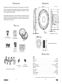
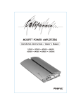
LIMITED WARRANTY
Profile Consumer Electronics, Inc. warrants this product to be free from defects in material and
workmanship for a period of One (1) year from the date of purchase by the original consumer
purchaser. If this product is proven to be defective within this one-year period, Profile will replace
it when said product is returned under instructions below, freight prepaid to Profile. This warranty
is valid only in the United States.
This warranty does not cover any expense incurred in the removal and/or reinstallation of this
product. This warranty does not cover damage caused by excess power usage than its published
power rating, accident, misuse, abuse, improper line voltage, fire, water, acts of God, or attempted
service by anyone other than Profile. This warranty does not cover broken cabinets or any other
accessories used in connection with this product or consequential damages due to a defect in the
product.
Any implied warranties, including fitness for use and merchantability, are limited in duration to the
period of the express warranty set forth above. No person is authorized to assume for Profile any
other liability in connection with the sale of the product. Profile expressly disclaims liability for
incidental and consequential damages that might be caused by this product. The remedies provided
under this warranty are exclusive and lieu of all others.
This warranty gives you specific legal rights. You may have other rights which vary from state to
state. Some states do not allow limitation on how long warranties last, so the above may not apply to
you. Additionally, some states do not allow the exclusion to limitation of consequential or incidental
damages, so the above limitation or exclusion may not apply to you.
To Obtain Warranty Service:
1) Return defective speaker(s) back to the purchased store for an exchange before
attempting to send products to Profile.
2) If you failed to obtain warranty service from the purchased store, send defective
speaker(s) freight prepaid to Profile including the following:
Sales receipt showing date and place purchased by an original owner, an
evidence that the unit is within the Warranty period.
Your clear return shipping address and a daytime phone number.
!
!
Send to:
Profile Consumer Electronics, Inc.
Speaker Exchange Dept.
15060 Shoemaker Ave.
Santa Fe Springs, CA 90670
* Please allow 2~3 weeks for an exchange, which includes transit times.
RECORD THE DATE AND PURCHASE LOCATION FOR FUTURE REFERENCE.
Model No. __________________
Purchase Date __________________
Purchased From ________________________
KEEP THIS INFORMATION AND YOUR SALES RECEIPT IN A SAFE PLACE.
2002 PROFILE CONSUMER ELECTRONICS
CP65 MANUAL REV 08.27.02
100000 - 082702
Manual By
PROFILE CONSUMER ELECTRONICS, INC. 15060 SHOEMAKER
SANTA FE SPRINGS, CA 90670
TEL: (562)404-9393 FAX: (562)404-9433 WWW.PROFILEUSA.COM
www.extremeconcepts.com
Installation Instructions / Owner's Manual
CP65
6 1/2” COMPONENT SPEAKER PACKAGE
DIMENSIONS
90 (3 1/2”)
182 (7 1/8”)
Before mounting the speakers, select a location that allows for at least 59 mm (2 5/16”) of
mounting depth. The speaker inside the door must not come in contact with the window when
rolled down. Additionally, the speaker should be out of the way of window cranks and door
handles allowing for normal operation.
168 (6 5/8”)
UNIT: mm (inches)
160 (6 1/4”)
Congratulations on your purchase of a Profile state-of-the-art speakers. Your selection of a
Profile car audio product indicates a true appreciation of fine musical reproduction. Whether
adding to an existing system or including your Profile speakers in a new system, you are certain
to notice immediate performance benefits.
142 (5 5/8”)
INTRODUCTION
PARTS LIST
5 (3/8”)
22 (7/8”)
59 (2 5/16”)
5 (3/16”)
MOUNTING DEPTH: 59 (2 5/16”)
TWEETER
MOUNTING HARDWARE
54 (2 1/8”)
FLUSH MOUNT
RETAINING RINGS
RETAINING CLIPS
MOUNTING
SCREWS
SIZE: 4 x 35mm
45 (1 3/4”)
GRILLES
TWEETER IN FLUSH MOUNTING KIT
16 (5/8”)
SPEAKER WIRES
LENGTH: 3m (9’ 10”)
SPECIFICATIONS
CP65
DOUBLE SIDED
TAPE
TWEETER HOUSING ASSORTMENT
CROSSOVER
MOUNTING SCREWS
Woofer . . . . . . . . . . . . . . . . . . . . . . . . . . . . . . . . . . . . . . . . . . . . . . . . . . . . . . . . . . . . . . . . . . . . . . 6 1/2"
Woofer Cone . . . . . . . . . . . . . . . . . . . . . . . . . . . . . . . . . . . . . . . . . . . . . . . . . . . . . . . . . . . . . . . . Injection
Tweeter . . . . . . . . . . . . . . . . . . . . . . . . . . . . . . . . . . . . . . . . . . . . . . . . . . . . . . . . . . . . . . 3/4” Silk Dome
Surround . . . . . . . . . . . . . . . . . . . . . . . . . . . . . . . . . . . . . . . . . . . . . . . . . . . . . . . . . . . . . . . . . . . . . Rubber
Nominal Input Power. . . . . . . . . . . . . . . . . . . . . . . . . . . . . . . . . . . . . . . . . . . . . . 10 ~ 85 Watts R.M.S.
Maximum Input Power . . . . . . . . . . . . . . . . . . . . . . . . . . . . . . . . . . . . . . . . . . . . . . . . . . . . . . 180 Watts
Impedance. . . . . . . . . . . . . . . . . . . . . . . . . . . . . . . . . . . . . . . . . . . . . . . . . . . . . . . . . . . . . . . . . . . . 4 Ohms
Magnet Weight. . . . . . . . . . . . . . . . . . . . . . . . . . . . . . . . . . . . . . . . . . . . . . . . . . . . . . . . . . . . . . . . . 15 Oz.
Sensitivity. . . . . . . . . . . . . . . . . . . . . . . . . . . . . . . . . . . . . . . . . . . . . . . . . . . . . . . . . . . . . . . . 89 dB/W/m
Frequency Response . . . . . . . . . . . . . . . . . . . . . . . . . . . . . . . . . . . . . . . . . . . . . . . . . . . 55 ~ 22,000 Hz
Crossover Type . . . . . . . . . . . . . . . . . . . . . . . . . . . . . . . . . . . . . . . . . . . . . . . . . . . . . . . . . . . . . . . . 2-Way
Due to continuing product improvements, design and specifications subject to change without notice.
1
6
SAFETY PRECAUTIONS
TWEETER MOUNTING OPTION # 2 - SURFACE MOUNT
Disconnect the battery.
DOUBLE SIDED
TAPE
For safety, disconnect the negative lead from the battery prior to beginning the installation.
Use high grade wire connectors.
To ensure maximum power transfer and secure safe connections, it is recommended to use
high grade barrier spades for connection at the crossover and amplifier (if equipped with
barrier style terminals).
MOUNTING TWEETER
WITHOUT DRILLING HOLES
MOUNTING TWEETER
WITH DRILLING HOLES
Do not run any wires underneath vehicle.
Exposed wires have a chance of being cut or damaged. It is best to run all wires through the
vehicle under the carpet and/or side panels. This lends to a cleaner installation and less risk of
damage.
TWEETER MOUNTING OPTION # 3 - ANGLE MOUNT
Use caution when mounting the speakers.
Remember there are many electrical wires, gas lines, vacuum lines, brake lines as well as a gas
tank in the automobile. Make sure you know where they are when mounting the speakers to
avoid puncturing lines, shorting wires or drilling holes in the gas tank.
Run speaker wires away from electrical wires.
To avoid possibility of induced noise from the car's electrical system (i.e. popping noises or
engine noise), run wires away from the car's electrical wiring.
CROSSOVER MOUNTING & CONNECTIONS
Avoid sharp edges when running the wires.
To avoid the possibility of power, signal or speaker shorts, be careful not to allow the
amplifiers wires to come in contact with sharp edges. Use a grommet to protect the wire when
running through the fire wall .
2-WAY CROSSOVER NETWORK
2-WAY CROSSOVER NETWORK
INPUT
To Amplifier
INPUT
-
+
WOOFER
-
+
-
TWEETER
-
+
WOOFER
-
+
TWEETER
-
+
+
Striped Wire
5
2
INSTALLATION (MIDBASS)
MARK THE CUT OUT AREA
AND DRILL HOLES. IF HOLE
EXISTS SKIP TO STEP
.
INSTALLATION (TWEETER)
CUT OUT SPEAKER MOUNTING AREA
THEN DRILL SCREW HOLES USING
3.3mm (5/32”) BIT.
FOR OPTIMUM FLEXIBILITY THERE ARE THREE MOUNTING OPTIONS FOR THE TWEETER. YOU
WILL NEED TO DECIDE WHICH IS BEST SUITED FOR YOUR APPLICATION.
3.3mm (5/32”)
145mm (5 3/4”)
ANGLE MOUNTING
FLUSH MOUNTING
CONNECT WIRE AT SPEAKERS.
INSERT RETAINING CLIP OVER HOLE
IN DOOR PANEL.
SOLID
COLOR WIRE
BLACK
STRIPED WIRE
TO CROSSOVER NETWORK
IMPORTANT!: THE LARGER HOLE ON
THE CLIP SHOULD BE ON THE FRONT
SIDE OF THE PANEL AND THE SMALLER
SPILT HOLE SHOULD BE ON THE BACK
SIDE OF THE PANEL.
SURFACE MOUNTING
TWEETER MOUNTING OPTION # 1 - FLUSH MOUNT
MARK THE CUT OUT AREA.
45mm (1 3/4”)
CUT OUT TWEETER MOUNTING AREA.
ASSEMBLE TWEETER AS SHOWN BELOW AND
RUN THE SPEAKERS WIRE THROUGH THE HOLE
THEN THROUGH THE RETAINING RING.
PUSH RETAINING RING AROUND BACK OF
TWEETER HOUSING UNTIL THE TWEETER IS
FLUSH WITH DOOR PANEL.
MOUNT SPEAKERS AND SNAP ON GRILLES.
IF YOU ARE MOUNTING SPEAKERS IN THE
VEHICLE’S FACTORY LOCATIONS, GRILLES
ARE NOT NEEDED.
3
4