1
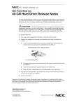
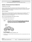
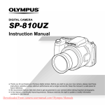
PT-9A Polarity Tester
Professional Speaker Calibration and Polarity Test Instrument
Many “Real World” Uses:
POLARITY +
CD
LINE
SIGNAL
POLARITY ON
OFF
POWER
LOW BATTERY
Check Speaker Connections
Check Absolute Speaker Polarity
Check Passive Crossover Phase Shift
Check OEM Amplifier Outputs
Identify Channel (No more drill batteries)
Check for Speaker Mounting Leaks
.......and so much more!
LINE OUT
PT-9A
User Manual
Mobile Solutions USA
2120 E. 6th Street, Suite 10
Tempe, AZ 85281
email - [email protected]
www.mobilesolutions-usa.com
Version 3.0
PT-9A Polarity Test Instrument
The PT-9A is an essential tool for mobile electronics installation. With proper use, it should aid you in achieving optimum
performance from any multi-speaker mobile audio system. Please read the user manual carefully and follow the instructions provided.
What is the Overall Goal?
The goal of any audio system with multiple speakers is to reproduce sound energy so that the phase between all speakers
is complimentary (rather than destructive). This means all speakers in the system need to be working together. The PT-9A
allows the install technician to verify the absolute phase of each speaker in the system, both individually and as a group
using a combination of internally generated pulses and pulses from the test CD.
Simple GREEN or RED light pulses on the front of the instrument indicate the overall condition of the speaker(s) being
evaluated in real time while installed in their final position(s) in the vehicle. It can’t get much more accurate than that!
Built-in Microphone (Front of Instrument)
Front Panel Layout
Polarity Indicators
Green = Positive (Pressure)
Red = Negative (Vacuum)
POLARITY +
CD
LINE
Signal Switch
OFF
Power Switch
SIGNAL
POLARITY ON
POWER
LOW BATTERY
Low Battery Indicator
(Illuminates Yellow when
9.6v battery requires
replacement)
-
LINE OUT
Line Level Pulse Generator
(Active when the Signal Switch
is in the LINE position)
PT-9A
+
SPEAKER
Speaker Level Pulse Generator
(Active when the Signal Switch is
in the LINE position)
About the Internal Pulse Generator
The PT-9A features an internal pulse generator output that simultaneously processes speaker pulses through the built-in
microphone located on the front of the instrument. This allows the unit to be entirely self contained. The internal generator
provides evenly spaced, positive (pressure) pulses to both the line level jack and speaker level outputs for the duration of
time the unit is on. The LINE LEVEL signal is sufficient to drive signal processor and amplifier inputs. The SPEAKER LEVEL signal
is sufficient to drive a speaker directly. To use the internal pulse generator, be sure the signal switch is in the LINE position.
Alternatively, the PT-9A can use only the built-in microphone to “hear” pulses generated by an external source, such as the
test CD provided. The test CD uses a sequence of 3 positive pulses followed by one negative pulse. Whenever the CD plays
the pulse track (Track 3), the speakers in the system will follow this pulsing sequence. To use only the built in microphone
and pulses from an external source, be sure the signal switch is in the CD position.
Noise Free Testing Zone
It’s very important that this instrument is used in an environment where there is not a high level or external ambient noise.
Often times an installation bay can contain a high level of noise during a productive day, so you may choose to close the vehicle doors and ask others nearby to minimize unnecessary noise. This will only help the accuracy of the built-in microphone.
Operating Instructions (Internal Pulse Generator)
1) Move the Power Switch of the test instrument to the ON position.
2) Move the Signal Switch of the test instrument to the LINE position.
3) Choose either the LINE OUT RCA connector or the SPEAKER connectors. If choosing LOW LEVEL RCA, proceed to step 4)
If choosing SPEAKER connectors, proceed to step 8.
Speaker Level
4) Connect the supplied test leads to the SPEAKER connector jacks. Connect the RED
probe to the + jack and connect the BLACK probe to the - jack. You should begin to
hear a faint high frequency pulsing sound spaced in about 1 second intervals.
5) Position the instrument about 10 inches (25.4cm) in front of the speaker.
6) All of the internal pulses from the instrument are positive, so your speaker should
be pulsing “out” and illuminating the GREEN light on the instrument. If it is lit RED,
this means the speaker is wired backward. Switch wiring and test again. *If GREEN
and RED are lit AT THE SAME time it may indicate a leaky speaker mount.
7) Repeat for other individual speakers as needed.
Note - if using in an OEM audio integration application where you are pulsing the
wires in a factory head unit or amplifier harness to find the speaker locations, you
may want to use smaller “backprobe pin” type leads and clip onto the PT-9A test
leads with an aligator clip as shown in the photo. This will eliminate any unnecessary damage to high density OEM wiring and connectors in the plug.
Line Level
8) Connect one RCA audio cable to the instrument. This can be the input cable to a signal processor or amplifier. Test one
channel at a time.
9) Make sure the processor or amplifier is turned on so signal can pass through the component to the speaker(s) connected
on that channel. You should begin to hear a faint high frequency pulsing sound spaced in about 1 second intervals.
10) Position the instrument about 10 inches (25.4cm) in front of the speaker(s) you want to test.
11) All of the internal pulses from the instrument are positive, so your speaker(s) should be pulsing “out” and illuminating
the GREEN light on the instrument. If it is lit RED, this means the speaker is wired backward, a phase shift switch on the
device in engaged, or there is a phase shift through a passive crossover network. Switch wiring, check settings, and test
again. *If GREEN and RED are lit AT THE SAME time it may indicate a leaky speaker mount.
12) Repeat for other individual speakers or channels as needed.
Operating Instructions (with Test CD)
1) Insert the test CD into the source unit. Press play and advance to Track 3. (Engage the REPEAT mode if available). Set volume where pulses are just audible.
2) Move the Power Switch of the test instrument to the ON position.
3) Move the Signal Switch of the test instrument to the CD position.
4) Position the instrument about 10 inches (25.4cm) in front of the speaker(s)
you want to test.
5) The sequence of the test CD is 3 positive pulses, than 1 negative pulse. Your
speaker(s) should be pulsing “out” and illuminating the GREEN light three
times, then RED one time. If it is lit opposite (3 RED, 1 GREEN), this means
the speaker is wired backward, a phase shift switch on the device in engaged,
or there is a phase shift through a passive crossover network. Switch wiring,
check settings, and test again. *If GREEN and RED are lit AT THE SAME time
it may indicate a leaky speaker mount.
6) Repeat for other individual speakers or channels as needed.
Test CD Tracks
Tracks 1-5 are test tracks for use with various instruments, including your ears. These tracks are helpful when making the
final adjustments to the audio system BEFORE doing any kind of equalization.
Tracks 1 & 2: Left Channel Pink Noise (1) and Right Channel Pink Noise (2)
Use tracks 1 & 2 for testing left and right balance with both your ears and an SPL meter. .
Track 3: Polarity Pulses
This track contains polarity pulses to be used in conjunction with the Phase Test Instrument. The sequence is three POSITIVE
pulses followed by one NEGATIVE pulse. When wired correctly and responding in absolute phase, speakers in the system
tested with the instrument should show three GREEN lights followed by one RED light.
Track 4: Correlated L+R Channel Pink Noise
Use this track in conjunction with a RTA (Real Time Analyzer) to test frequency response.
Track 5: Zero Data (0 bits)
Use this track to check the system’s noise floor. Play this track with the volume on the source unit all the way up; you should
not hear any hiss. If there is any hiss in the system it often is an indication of excessive gain adjustment. To remedy this, try
turning the gain control on the amplifier(s) down to a level where the hiss is acceptable and play the system to evaluate
overall impact on maximum volume.
Test CD Tracks (Cont)
Tracks 6 through 18 are test tracks at specific frequencies sine wave at 0dB, -5dB and -10dB levels. One common use is to
test resonance, vibrations and speakers break-up during x-over adjustment and level setting. -5 and -10dB tracks can be
used to set gain for amplifiers. (Please note that extended play of these test tones can damage speakers permanently - use
caution at high volumes).
Track 6: 40 Hz Sine Wave - Use this track to test resonance or vibrations from the Subwoofer
Track 7: 40 Hz Sine Wave (-5dB) - Use this set signal processor or amplifier gains (critical listener)
Track 8: 40 Hz Sine Wave (-10dB) - Use this set signal processor or amplifier gains (non-critical listener or bass head)
Track 9: 100 Hz Sine Wave - Use this track to test Midbass speakers and Subwoofer
Track 10: 400 Hz Sine Wave - Use this track for Midbass and Midrange speakers
Track 11: 1 kHz Sine wave - Use this track for Midrange speakers
Track 12: 1 kHz Sine Wave (-5dB) - Use this set signal processor or amplifier gains (critical listener)
Track 13: 1 kHz Sine Wave (-10dB) - Use this set signal processor or amplifier gains (non-critical listener)
Track 14: 4 kHz Sine Wave - Use this track for Tweeters
Track 15: 4 kHz Sine Wave (-5dB) - Use this set signal processor or amplifier gains (critical listener)
Track 16: 4 kHz Sine Wave (-10dB) - Use this set signal processor or amplifier gains (non-critical listener)
Track 17: 8 kHz Sine wave - Use this track for Tweeters, particularly if the high pass crossover is above the previous 4kHz track
Track 18: Sine Sweep 20 Hz to 12 kHz - Use this track to check for overall system frequency response. Additionally, the Sine
Sweep track is useful for pinpointing any troublesome resonant panels in (or on) the vehicle.
To purchase additional Test CD’s, please contact Mobile Solutions USA
[email protected] or visit us on the web - www.mobilesolutions-usa.com