1
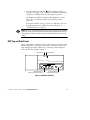
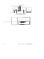
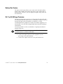
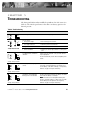
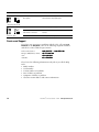
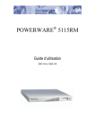
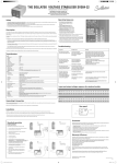
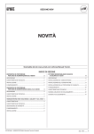
®
POWERWARE 3110
300–700 VA
User’s Guide
www.powerware.com
Class B EMC Statements
FCC Part 15
NOTE This equipment has been tested and found to comply with the limits for a Class B digital device, pursuant to
part 15 of the FCC Rules. These limits are designed to provide reasonable protection against harmful interference in a
residential installation. This equipment generates, uses and can radiate radio frequency energy and, if not installed and
used in accordance with the instructions, may cause harmful interference to radio communications. However, there is no
guarantee that interference will not occur in a particular installation. If this equipment does cause harmful interference to
radio or television reception, which can be determined by turning the equipment off and on, the user is encouraged to try
to correct the interference by one or more of the following measures:
S
Reorient or relocate the receiving antenna.
S
Increase the separation between the equipment and the receiver.
S
Connect the equipment into an outlet on a circuit different from that to which the receiver is connected.
S
Consult the dealer or an experienced radio/TV technician for help.
ICES-003
This Class B Interference Causing Equipment meets all requirements of the Canadian Interference Causing Equipment
Regulations ICES-003.
Cet appareil numérique de la classe B respecte toutes les exigences du Reglement sur le matériel brouilleur du Canada.
Requesting a Declaration of Conformity
Units that are labeled with a CE mark comply with the following harmonized standards and EU directives:
S
Harmonized Standards: EN 50091-1-1 and EN 50091-2
S
EU Directives: 73/23/EEC, Council Directive on equipment designed for use within certain voltage limits
93/68/EEC, Amending Directive 73/23/EEC
89/336/EEC, Council Directive relating to electromagnetic compatibility
92/31/EEC, Amending Directive 89/336/EEC relating to EMC
The EC Declaration of Conformity is available upon request for products with a CE mark. For copies of the EC
Declaration of Conformity, contact:
Powerware Corporation
Koskelontie 13
FIN-02920 Espoo
Finland
Phone: +358-9-452 661
Fax: +358-9-452 665 68
Powerware is a registered trademark of Powerware Corporation.
ECopyright 2001-2003 Powerware Corporation, Raleigh, NC, USA. All rights reserved. No part of this document may be
reproduced in any way without the express written approval of Powerware Corporation.
TABLE OF CONTENTS
1
Installation . . . . . . . . . . . . . . . . . . . . . . . . . . . . . . . . . . . . . . . . . . . . . . . . . .
1
Inspecting the Equipment . . . . . . . . . . . . . . . . . . . . . . . . . . . . . . . . . . . . . . . . . . . . . . . . . . . . .
Safety Precautions . . . . . . . . . . . . . . . . . . . . . . . . . . . . . . . . . . . . . . . . . . . . . . . . . . . . . . . . . .
Quick Startup . . . . . . . . . . . . . . . . . . . . . . . . . . . . . . . . . . . . . . . . . . . . . . . . . . . . . . . . . . . . .
UPS Top and Side Panels . . . . . . . . . . . . . . . . . . . . . . . . . . . . . . . . . . . . . . . . . . . . . . . . . . . . .
1
1
2
3
Features . . . . . . . . . . . . . . . . . . . . . . . . . . . . . . . . . . . . . . . . . . . . . . . . . . . . .
5
Communication Options . . . . . . . . . . . . . . . . . . . . . . . . . . . . . . . . . . . . . . . . . . . . . . . . . . . . . .
USB Port . . . . . . . . . . . . . . . . . . . . . . . . . . . . . . . . . . . . . . . . . . . . . . . . . . . . . . . . . . . . . .
DB-9 Communication Port . . . . . . . . . . . . . . . . . . . . . . . . . . . . . . . . . . . . . . . . . . . . . . . . . .
Battery Start Feature . . . . . . . . . . . . . . . . . . . . . . . . . . . . . . . . . . . . . . . . . . . . . . . . . . . . . . . .
RJ-11 or RJ-45 Surge Protectors . . . . . . . . . . . . . . . . . . . . . . . . . . . . . . . . . . . . . . . . . . . . . . . .
5
5
6
7
7
UPS Maintenance . . . . . . . . . . . . . . . . . . . . . . . . . . . . . . . . . . . . . . . . . . . . .
9
UPS and Battery Care . . . . . . . . . . . . . . . . . . . . . . . . . . . . . . . . . . . . . . . . . . . . . . . . . . . . . . . .
Storing the UPS . . . . . . . . . . . . . . . . . . . . . . . . . . . . . . . . . . . . . . . . . . . . . . . . . . . . . . . . .
Replacing Batteries . . . . . . . . . . . . . . . . . . . . . . . . . . . . . . . . . . . . . . . . . . . . . . . . . . . . . . . . .
Recycling the Used Battery . . . . . . . . . . . . . . . . . . . . . . . . . . . . . . . . . . . . . . . . . . . . . . . . . . . .
9
9
9
11
4
Specifications . . . . . . . . . . . . . . . . . . . . . . . . . . . . . . . . . . . . . . . . . . . . . . . .
13
5
Troubleshooting . . . . . . . . . . . . . . . . . . . . . . . . . . . . . . . . . . . . . . . . . . . . . .
15
Service and Support . . . . . . . . . . . . . . . . . . . . . . . . . . . . . . . . . . . . . . . . . . . . . . . . . . . . . . . . .
16
2
3
Powerware® 3110 User’s Guide S Rev B www.powerware.com
i
Table of Contents
ii
Powerware® 3110 User’s Guide S Rev B www.powerware.com
CHAPTER
1
INSTALLATION
This section explains:
S
S
S
S
Equipment inspection
Safety precautions
UPS installation
UPS top and side panels
Inspecting the Equipment
If any equipment has been damaged during shipment, keep the shipping
cartons and packing materials for the carrier or place of purchase and
file a claim for shipping damage. If you discover damage after
acceptance, file a claim for concealed damage.
To file a claim for shipping damage or concealed damage: 1) File with
the carrier within 15 days of receipt of the equipment; 2) Send a copy of
the damage claim within 15 days to your service representative.
Safety Precautions
Read the following precautions before you install the UPS.
IMPORTANT SAFETY INSTRUCTIONS
SAVE THESE INSTRUCTIONS. This manual contains important instructions that you
should follow during installation and maintenance of the UPS and batteries. Please
read all instructions before operating the equipment and save this manual for future
reference.
WARNING
S This UPS contains its own energy source (batteries). The output receptacles may
carry live voltage even when the UPS is not connected to an AC supply.
S Do not remove or unplug the input cord when the UPS is turned on. This removes
the safety ground from the UPS and the equipment connected to the UPS.
Powerware® 3110 User’s Guide S Rev B www.powerware.com
1
Installation
S To reduce the risk of fire or electric shock, install this UPS in a temperature and
humidity controlled, indoor environment, free of conductive contaminants. Ambient
temperature must not exceed 40°C (104°F). Do not operate near water or
excessive humidity (95% max).
S With the exception of the user-replaceable battery, all servicing of this equipment
must be performed by qualified service personnel.
S Before maintenance or repair, all connections must be removed. Before
maintenance, repair, or shipment, the unit must be completely switched off and
unplugged or disconnected.
CAUTION
S Important Notice The UPS ground (earth) conductor carries leakage current from
the loads in addition to any leakage current generated by the UPS. This UPS
generates no more than 0.5 mA of current (120V model), or 1 mA of current (230V
model).
S To limit the total leakage current to 3.5 mA, the load leakage must be limited to
3 mA on the 120V model and 2.5 mA on the 230V model.
S If you do not know the load leakage current, replace the UPS power cord (230V
model only) with a power cord that uses a locking plug with a minimum rating of
10A (such as IEC 309).
S If you do not have a matching receptacle, consult an electrician to install the
proper receptacle.
S The three-wire receptacle that you plug the UPS into must have a good
(low-impedance) ground (protective earth) connection to provide a safe path for
leakage current.
Quick Startup
The PowerwareR 3110 provides protection against many power
problems, including power outages. It also provides spike suppression
and line noise filtering to protect your equipment.
1. On 230V models, plug the UPS power cord into the input
connector on the UPS side panel.
2. Plug the equipment to be protected into the UPS output
receptacles.
DO NOT protect laser printers with the UPS because of the
exceptionally high power requirements of the heating elements.
2
Powerware® 3110 User’s Guide S Rev B www.powerware.com
Installation
3. Start the UPS by pressing the switch as shown in Figure 2
or Figure 4 on page 4. The µ indicator illuminates indicating
that power is available from the UPS output receptacles.
The unit beeps and the front panel LEDs illuminate several
times. The µ indicator remains on, indicating normal
operation.
If the unit continues to beep, or if the µ indicator is off even
though input power is available from the wall outlet, see
“Troubleshooting” on page 15.
NOTE Let the unit charge the battery for at least 3 hours. You may use the unit while
the battery charges, but the battery backup runtime will be reduced until the battery is
fully charged. This will take up to 8 hours after a full discharge while the UPS is fully
loaded.
UPS Top and Side Panels
Figure 1 and Figure 2 identify features of the 120V (USA) models, with
attached input line cord. Figure 3 and Figure 4 identify features of the
230V (European) models, which have a connector for the input line
cord as well as IEC output receptacles.
Fault Indicator
Output Receptacles
(Battery and Surge Protection)
Power Indicator
Output Receptacles
(Surge Protection Only)
Figure 1. 120V Model Top Panel
Powerware® 3110 User’s Guide S Rev B www.powerware.com
3
Installation
RJ-11 or RJ-45 Surge Protectors
Circuit Breaker
Power Cord
Communication Port
USB Port
On/Standby Switch
Figure 2. 120V Model Side Panel
4
Powerware® 3110 User’s Guide S Rev B www.powerware.com
CHAPTER
2
FEATURES
This section covers:
S Using the USB or DB-9 communication port
S Starting the UPS on battery
Communication Options
The UPS is equipped with a USB and a DB-9 communication port. Either
the USB port or the DB-9 communication port may be used to monitor
the UPS; however, they cannot operate simultaneously.
USB Port
The UPS can communicate with a USB-compliant computer using
LanSafe Power Management Software (v4.15 or higher).
To establish communication between the UPS and a computer:
1. Connect the USB cable to the USB port on the UPS rear panel.
Connect the other end of the USB cable to the USB port on your
computer.
2. Install the LanSafe software and USB drivers according to the
instructions provided with the Powerware Software Suite CD.
Powerware® 3110 User’s Guide S Rev B www.powerware.com
5
Features
DB-9 Communication Port
Powerware offers an accessory interface kit that allows you to connect
many types of computer systems to the UPS communication port. For
specific information on Powerware interface kits, call your service
representative.
Contacts consist of open collector circuits capable of switching up to
+30 Vdc, 6 mA resistive load.
Table 1. Communication Port Pin Assignment
Pin
Signal Type
Function
1
RS-232 Level Shutdown
+12 Vdc signal held for 5 seconds on this pin shuts the UPS down
120 seconds later. The UPS restarts after 15 seconds when utility
power returns.
2
Not Used
Not Used
3
Normally Open On-Battery Contact
A normally open contact that closes 15 seconds (pulls to
Common) after the UPS switches to battery power.
4
Common
The signal ground for all signal pins.
5
Normally Open Low-Battery-Alarm Contact
A normally open contact that closes (pulls to Common) during a
Low Battery Alarm.
6
Normally Closed Low-Battery-Alarm Contact
A normally closed contact that opens (releases from Common)
during a Low Battery Alarm. This tells some shutdown software
when to start a computer shutdown.
7
Not Used
Not Used
8
Normally Closed On-Battery Contact
A normally closed contact that opens 15 seconds (releases from
Common) after the UPS switches to battery power.
9
Not Used
Not Used
6
Powerware® 3110 User’s Guide S Rev B www.powerware.com
Features
Battery Start Feature
The Battery Start feature allows you to turn on the UPS when utility
power is not available. The battery-start range is up to about 40% of
nominal input; otherwise, the UPS displays an input voltage fault and
the alarm beeps.
RJ-11 or RJ-45 Surge Protectors
The RJ-11 or RJ-45 surge protectors are located on the side panel and
are labeled IN and OUT. This feature accommodates an RJ-11 connector
that provides protection for modems, fax machines, or other
telecommunications equipment. As with most modem equipment, it is
not advisable to use this jack in digital PBX (Private Branch Exchange)
environments.
Low voltage models can also accommodate a single RJ-45 (10BaseT)
network connector.
NOTE DO NOT connect any network equipment to the 230V models; only telephone or
fax/modem protection is available for 230V models.
1. Connect the input connector of the equipment you are
protecting to the jack labeled IN.
2. Connect the output connector to the jack labeled OUT.
Powerware® 3110 User’s Guide S Rev B www.powerware.com
7
Features
8
Powerware® 3110 User’s Guide S Rev B www.powerware.com
CHAPTER
3
UPS MAINTENANCE
This section explains how to:
S Care for the UPS and batteries
S Replace the batteries
S Recycle used batteries
UPS and Battery Care
For the best preventive maintenance, keep the area around the UPS
clean and dust-free. If the atmosphere is very dusty, clean the outside of
the system with a vacuum cleaner.
For full battery life, keep the UPS at an ambient temperature of
25°C (77°F).
Storing the UPS
If you store the UPS for a long period, recharge the battery every
6 months by plugging the UPS into a power outlet.
Replacing Batteries
Before replacing the battery, make sure that you read the safety
information below.
WARNING
S Batteries can present a risk of electrical shock or burn from high short circuit
current. The following precautions should be observed: 1) Remove watches, rings,
or other metal objects; 2) Use tools with insulated handles; 3) Do not lay tools or
metal parts on top of batteries.
S ELECTRIC ENERGY HAZARD. Do not attempt to alter any battery wiring or
connectors. Attempting to alter wiring can cause injury.
S Replace batteries with the same number and type of batteries as originally
installed in the UPS.
S DO NOT DISCONNECT the batteries while the UPS is in Battery mode.
Powerware® 3110 User’s Guide S Rev B www.powerware.com
9
UPS Maintenance
CAUTION
The 230V models require replacement by qualified service personnel.
1. Contact your service representative to order a replacement
battery. It must be the same type and rating as the original
battery (see Table 3 on page 14).
2. Switch off and unplug the protected equipment from the UPS.
3. Turn off the UPS and disconnect the power cord.
4. Turn the UPS upside down.
Battery
Battery Cover
Figure 5. Removing the Battery Cover and Battery
5. Remove the battery cover:
Models 550 and 700 – Use a screwdriver to remove the four screws
securing the battery cover and lift the battery cover off.
Model 300 – Press down on the battery cover tabs and slide the
battery cover off.
6. Lift the battery up and out of the case.
7. Disconnect the red and black cables from the used battery.
8. Replace the battery. See “Recycling the Used Battery” for proper
disposal.
9. Reconnect the cables to the new battery; red to positive (+),
black to negative (– ), and slide the battery back into the case.
10
Powerware® 3110 User’s Guide S Rev B www.powerware.com
UPS Maintenance
10. Replace the battery cover by pushing the cover until it snaps
into place securely. Replace any battery cover screws that were
removed to access the battery.
11. Turn the UPS right side up. Reconnect the UPS power cord and
turn the unit on.
12. Reconnect the equipment. Switch on the protected equipment
one piece at a time.
Recycling the Used Battery
Contact your local recycling or hazardous waste center for information
on proper disposal of the used battery.
WARNING
S Do not dispose of the battery or batteries in a fire. Batteries may explode. Proper
disposal of batteries is required. Refer to your local codes for disposal
requirements.
S Do not open or mutilate the battery or batteries. Released electrolyte is harmful to
the skin and eyes. It may be toxic.
CAUTION
Do not discard the UPS or the UPS batteries in the trash. This product contains sealed,
lead-acid batteries and must be disposed of properly. For more information, contact
your local recycling or hazardous waste center.
Powerware® 3110 User’s Guide S Rev B www.powerware.com
11
UPS Maintenance
12
Powerware® 3110 User’s Guide S Rev B www.powerware.com
CHAPTER
4
SPECIFICATIONS
Powerware Corporation reserves the right to change specifications
without prior notice.
Table 2. Electrical
Nominal Voltage
120V Model
230V Model
120V
230V
Power Factor
Voltage Range
0.6
Online: 90–152V
On Battery: 0–100V and 152–160V
Nominal Frequency
Online: 176–272V
On Battery: 0–192V and 272–290V
50/60 Hz auto-sensing
57–63 Hz (60 Hz)
47–53 Hz (50 Hz)
Efficiency
(Normal mode)
> 95%
Noise Filtering
Full-time EMI/RFI filtering
Overcurrent Protection
Resettable circuit breaker
Connections
Power Levels
(rated at nominal
inputs)
Attached 5-15P power cord
IEC 320-C14 input connector
Input fault current: 15A maximum
PW3110 300: 300 VA, 180W
PW3110 550: 550 VA, 330W
PW3110 700: 700 VA, 420W
PW3110 300i: 300 VA, 180W
PW3110 550i: 550 VA, 330W
PW3110 700i: 700 VA, 420W
Total Output Current
Load Compatibility
Output Frequency
(Battery mode)
Connections
10A maximum
Switch-mode power supply or resistive load
50/60 Hz ±1 Hz of nominal frequency
(4) 5-15 receptacles with UPS
and surge protection
(2) 5-15 receptacles with surge
protection only
Powerware® 3110 User’s Guide S Rev B www.powerware.com
(4) IEC 320-C13 receptacles with UPS
and surge protection
(2) IEC 320-C13 receptacles with surge
protection only
13
Specifications
Table 3. Battery
Configuration
300 VA: (1) 12V, 4.2 Ah or (2) 6V, 4.0 Ah internal battery(s)
550 VA: (1) 12V, 7.0 or 7.2 Ah internal battery
700 VA: (1) 12V, 9 Ah internal battery
Voltage
12 Vdc
Type
Sealed, maintenance-free, valve-regulated, lead-acid
Charging
8 hours to 95% capacity with output fully loaded
Monitoring
Advanced monitoring for earlier failure detection and warning
Backup Time
300– 550 VA: 3 minutes at full load; 5 minutes typical load
700 VA: 2.5 minutes at full load; 5 minutes typical load
Transfer Time
4 ms typical
Table 4. Weights and Dimensions
UPS Dimensions
(HxWxD)
300 VA: 5.9 x 39.3 x 15.0 cm (2.3I x 15.5I x 5.9I)
550– 700 VA: 7.9 x 37.6 x 17.2 cm (3.1I x 14.8I x 6.8I)
UPS Weight
300 VA: 3.0 kg (6.6 lb)
550 VA: 4.2 kg (9.2 lb)
700 VA: 4.3 kg (9.4 lb)
Table 5. Environmental and Safety
120V Model
Operating Temperature
Storage Temperature
Ventilation
230V Model
0°C to 40°C (32°F to 104°F)
-15°C to 50°C (-5°F to 122°F)
If the UPS is stored, the batteries should be recharged every 6 months.
If stored above 25°C (77°F), battery life is reduced and should be recharged more often.
Air around the unit must be free of dust, chemicals, or other materials
that corrode or contaminate.
Relative Humidity
Audible Noise
5– 95% RH noncondensing
Online: Less than 40 dBA typical at one meter
On Battery: Less than 45 dBA typical at one meter
Surge Energy Rating
450 joules
Surge Suppression
ANSI C62.41 Category A (formerly IEEE 587)
IEC 61000-4-5, Level 3
Safety Conformance
UL 1778; UL 497A;
CAN/CSA C22.2, No. 107.1
EN 50091-1-1 and EN 60950
UL, cUL
NEMKO, CE
FCC Part 15, ICES-003
EN 50091-2
Safety Markings
EMC (Class B)
14
Powerware® 3110 User’s Guide S Rev B www.powerware.com
CHAPTER
5
TROUBLESHOOTING
The front panel LEDs and an audible beep indicate the UPS status (see
Table 6). The UPS beeps whenever the unit is on battery power or an
alarm is present.
Table 6. Troubleshooting
Alarm or Condition
1 beep every 5 seconds
seconds.
Possible Cause
What to Do
Normal operation.
None. The UPS is operating in Normal mode.
Line loss due to:
S Utility power outage.
S Wait for utility power to return.
S Loose plug connection.
S Check the power cord connections.
S Tripped circuit breaker.
S Reset the circuit breaker.
S Power cord failure.
S Contact your service representative for a new power
cord.
Low battery alarm; shutdown is
imminent.
Prepare for a UPS shutdown. Save your work and turn
off your equipment.
The unit automatically restarts when acceptable power
returns.
The battery needs charging or
service.
Turn the UPS off and plug the UPS into a power outlet
for 24 hours to charge the battery. Turn the UPS on to
test the battery. If the alarm still beeps, see “Replacing
Batteries” on page 9 to replace the battery.
The battery is discharged and
battery power is not available.
The UPS automatically recharges the battery. The alarm
clears when the battery is recharged.
NO TE If the UPS has not recharged the battery after
24 hours, the alarm changes to 3 beeps every 5 seconds
and the battery must be replaced. See “Replacing
Batteries” on page 9 to replace the battery.
2 beeps every 5 seconds.
3 beeps every 5 seconds.
3 beeps every 5 minutes.
Powerware® 3110 User’s Guide S Rev B www.powerware.com
15
Troubleshooting
Alarm or Condition
Possible Cause
What to Do
Power requirements exceed the
UPS capacity.
Remove some of the equipment from the UPS. You may
need to obtain a larger capacity UPS.
Output short circuit.
Turn off or unplug the equipment connected to the UPS.
Input voltage is out of range
when the UPS is turned on.
Turn off the UPS until acceptable input voltage
restored.
UPS fault.
Contact your service representative.
1 beep every half second.
Continuous beep.
Service and Support
If you have any questions or problems with the UPS, call your Local
Distributor or the Help Desk at one of the following telephone numbers
and ask for a UPS technical representative.
In the United States:
Europe, Middle East, Africa:
Asia:
Australia:
1- 800- 356- 5737 or 1- 608- 565- 2100
+ 4 4- 1 7 5 3 6 0 8 7 0 0
+ 8 5 2- 2 8 3 0- 3 0 3 0
+ 6 1- 3- 9 7 0 6- 5 0 2 2
Please have the following information ready when you call the Help
Desk:
S Model number
S Serial number
S Version number (if available)
S Date of failure or problem
S Symptoms of failure or problem
S Customer return address and contact information
16
Powerware® 3110 User’s Guide S Rev B www.powerware.com
Troubleshooting
18
Powerware® 3110 User’s Guide S Rev B www.powerware.com