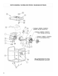
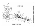
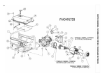
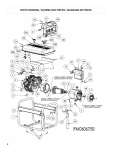
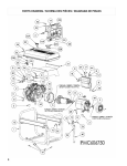
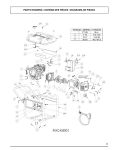
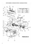
1
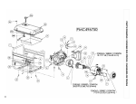
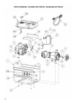
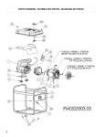
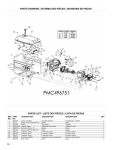
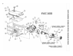
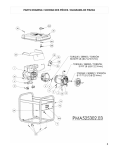
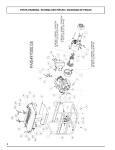
PORTABILITY KIT INSTALLATION
TOOLS REQUIRED: 7/16”, 1/2” and 9/16” sockets and
ratchets, block(s) of wood (minimum of 6” tall).
Refer to the parts list on page 9.
WHEEL INSTALLATION
1. Block up end of generator opposite the fuel tank cap to
install wheel kit.
2. Insert wheel spacer (item 20) into the center of the wheel
(item 35).
3. Slide 3/8 x 4.75” bolt (item 10) through the 3/8 washer
(item 29) and wheel (item 35), then through the wheel
bracket on the carrier, with the offset side of the wheel hub
against the wheel bracket.
4. Thread 3/8 nyloc nut (item 11) onto the bolt and tighten to
securely clamp the wheel assembly to the tubing.
5. Repeat above instructions for the remaining wheel.
LIMITED WARRANTY
Warranty Coverage: Powermate Corporation (the Company)
warrants to the original retail customer in North America that it
will repair or replace, free of charge, any parts found by the
Company or its authorized service representative to be
defective in material or workmanship. This warranty covers the
cost of replacement parts and labor for defects in material or
workmanship.
FOOT INSTALLATION
1. Blocking up the engine side of the generator, place a
spacer (item 43) and a foot (item 37) under the carrier
channel. Thread a 5/16-18 x 2.75” bolt (item 8) through
the mounting holes and thread a 5/16 washer (item 40) and
a 5/16 nyloc nut (item 15) to the bolt to secure the foot to
the carrier. Caution: Do not over tighten so that the foot
material collapses.
2. Repeat step 1 for the remaining foot.
Not Covered:
·
Transportation charges for sending the product to the
Company or its authorized service representative for
warranty service, or for shipping repaired or replacement
products back to the customer; these charges must be
borne by the customer.
·
Engine is covered exclusively by a separate warranty from
the engine manufacturer, included with the engine Manual.
·
Damages caused by abuse or accident, and the effects of
corrosion, erosion and normal wear and tear.
·
Warranty is voided if the customer fails to install, maintain
and operate the product in accordance with the instructions
and recommendations of the Company set forth in the
owner's manual, or if the product is used as rental
equipment.
The Company will not pay for repairs or adjustments to the
·
product, or for any costs or labor, performed without the
Company's prior authorization.
HANDLE INSTALLATION
1. Place the handle (item 31) onto the reduced portion of the
upright tubes of the base as shown in the diagram.
2. Install the 1/4-20 x 1.75” bolts (item 32) through the tubes
from the outside.
3. Thread the 1/4” nyloc nuts (item 13) onto the bolts and
tighten. NOTE: Do not over tighten.
Warranty Period: Three (3) years from the date of purchase
on products used solely for consumer applications; if a product
is used for business or commercial applications, the warranty
period will be limited to one (1) year from the date of purchase.
For warranty service, the customer must provide dated proof of
purchase and must notify the Company within the warranty
period.
For warranty service: Call toll free 800-445-1805, or write
to Powermate Corporation, Product Services, 4970 Airport
Road, P. O. Box 6001, Kearney, NE 68848.
EXCLUSIONS AND LIMITATIONS: THE COMPANY MAKES
NO OTHER WARRANTY OF ANY KIND, EXPRESS OR
IMPLIED. IMPLIED WARRANTIES, INCLUDING
WARRANTIES OF MERCHANTABILITY AND OF FITNESS
FOR A PARTICULAR PURPOSE, ARE HEREBY
DISCLAIMED. THE WARRANTY SERVICE DESCRIBED
ABOVE IS THE EXCLUSIVE REMEDY UNDER THIS
WARRANTY; LIABILITY FOR INCIDENTAL AND
CONSEQUENTIAL DAMAGES IS EXCLUDED TO THE
EXTENT PERMITTED BY LAW.
This warranty gives you specific legal rights, and you may also
have other rights which vary from state to state. Some states
do not allow a disclaimer of implied warranties, or the exclusion
or limitation of incidental and consequential damages, so the
above disclaimers and exclusions may not apply to you.
English
3
PARTS DRAWING / SCHEMA DES PIÈCES / DIAGRAMA DE PIEZAS
8
PARTS LIST / LISTE DES PIÈCES / LISTA DE PIEZAS
REF. PART
NO. NO.
DESCRIPTION
1
2
3
4
5
6
7
8
9
10
11
12
13
14
15
16
17
18
19
20
21
22
23
24
24A
25
26
27
27A
27B
27C
27D
28
29
30
31
32
33
34
35
36
37
38
39
40
41
42
43
44
45
46
47
48
49
50
Carrier, assembly
Engine 10 hp Yamaha OHV
Isolator
Washer, star external 1/4
Bolt whz 3/8-16 x 1.25
Connector, panel
Connector, stator
Bolt, hex 5/16-18 x 2.75
Washer, lock 5/16
Bolt, 3/8-16 x 4.75
Nut, nyloc 3/8-16
Lug, ground
Nut, nyloc 1/4-20
Bolt, 5/16-18 x 1.25
Nut, nyloc 5/16-18
Nut, hex flg 5/16-18
Assembly, ground wire
Washer, star external 5/16
Bolt, hex 5/16-18 x .75
Spacer .38 ID
Muffler
Gasket
Bolt, 5/16-18 x 1.50
Panel, wired
Circuit Protector 25 amp
Bolt M8 x 16mm
Shield, heat
Fuel tank assembly
Fuel Cap
Fuel shut off with filter
Fuel Bushing
Fuel connector
Module, low oil
Washer, flat 3/8
Bracket, low oil
Handle
Bolt, 1/4-20 x 1.75
Cordset, 25 foot 30 amp
Bolt, 1/4-20 x .75
Wheel
Switch, Rocker
Foot rubber
Screw #6-19 x .50 Torx
Washer Nylon .25 ID
Washer, flat 5/16 W
Bolt, 1/4-20 x 1.25
J clamp
Spacer, foot
Oil warning light
Nut M8
Plastic cover
Screw, #6-19 x 1
Plastic bezel
Gasket
Cord KeeperTM
0065251
Note A
0051094
Note B
0057512
0062196
0056716
Note B
Note B
Note B
0057578
0008854
0040832
Note B
0048736
0057254
0049224
Note B
Note B
0065274
0065185
0063701
Note B
0065264
0049072
0049268
0065278
Note C
0064057
0061756
0062673
0064306
0064107
Note B
0063830
0065271
Note B
0063876
Note B
0062058
0050298
0055894
0062020
0062093
0049352
Note B
0052931
0062932
0064072
0062567
0065180
0065216
0065179
0065181
0055982.01
DESCRIPTION
Ensemble transport
Moteur
Sectionneur
Rondelle à dents externa 1/4
Boulon
Connecteur, tableau
Connecteur, stator
Boulon
Contre-écrou 5/16
Boulon
Écrous nyloc 3/8-16
Oeillet de mise à la terre
Écrous nyloc 1/4-20
Boulon
Écrous nyloc 5/16-18
Écrous 5/16-18
Ensemble fil de mise à la terre
Rondelle à dents externa 5/16
Boulon, tête hex 5/16-18 x 3/4
Entretoise
Silencieux
Joint
Boulon
Tableau compl. câblé
Protecteur de circuit 25 amp
Boulon M8 x 16mm
Écran de chaleur
Assemb. complet du réservoir
Capuchon
Robinet de carburant
Bague d’essence
Connecteur à carburant
Module, bas niveau d'huile
Rondelle plates 5/16
Support, bas niveau d'huile
Poignée
Boulon
Ensemble de cordons, 25 pieds 30A
Boulon
Roue
Interrupteur
Pied
Vis
Rondelle en nylon
Rondelle plates 5/16 large
Boulon
Collier
Entretoise
Huiler l'Avertissement Allume
Écrous M8
Couvercle en plastique
Vis
Cadre en plastique
Joint
Cord KeeperTM
DESCRIPCIÓN
Transportador, conjunto
Motor
Aislador
Arandela, estrella 1/4
Perno
Conector, panel
Conector, estator
Perno
Arandela, de cierre 5/16
Perno
Tuerca, nyloc 3/8-16
Terminal, tierra
Tuerca, nyloc 1/4-20
Perno
Tuerca, nyloc 5/16-18
Tuerca, 5/16-18
Conjunto, câble de tierra
Arandela, estrella 5/16
Perno 5/16-18 x 3/4
Espaciador
Silenciador
Empaquetadura
Perno
Panel, cabeado completo
Protector de circuito 25 amp
Perno M8 x 16mm
Pantalla para el calor
Conjunto tanque
Tapa de combustible
Válvula combustible con filtro
Buje de combustible
Conector combustible
Módulo, nivel bajo de aceite
Arandela, plana 5/16
Soporte, nivel bajo de aceite
Manija
Perno
Juego de cordón, 25 pies 30 amperios
Perno
Rueda
Interruptor
Pie
Tornillo
Arandela del nilón
Arandela, plana 5/16 lejos
Perno
Pinza vinílica
Espaciador
La luz de la advertencia para el aceite
Tuerca M8
Cubierta de plástico
Tornillo
Bisel de plástico
Empaque
Cord Keeper TM
QTY
1
1
4
2
4
2
1
2
10
2
2
1
8
2
2
5
1
2
1
2
1
1
2
1
2
3
1
1
1
1
1
1
1
2
1
1
6
1
1
2
1
2
4
4
2
1
1
2
1
2
1
5
1
1
2
9
PARTS LIST / LISTE DES PIÈCES / LISTA DE PIEZAS
Ref
No.
Part
No.
51
51A
51B
51C
51D
51E
51F
51G
51H
51I
0064680
0064681
0064518
0064519
0064520
0064521
0064522
0064523
0064524
0064525
51J 0064526
51K 0064527
51L 0064532
51M 0064636
51N 0064637
51O 0064536
51P 0064537
51Q 0058933
51R Note B
51S 0046540.03
10
Description
Generator head, Senci
Adapter, engine
Rotor
Stator
Band, stator cover
Bolt, M6 x 180
Support, bearing
Brush module
Screw flg M5 x 16mm
AVR module
Bolt, M5 x 220
Nut, nyloc M5
Cover, end
Screw M5 x 12
Washer M5
Bearing
Stator harness
Washer 1/4 wide
Washer lock 5/16
Bolt, hex 5/16-24 x 9.00
Description
Tête de la génératrice,
Adaptateur pour moteur
Rotor
Stator
Bande
Boulon
Support, roulement
Brosser le module
Vis
La tension automatique
régulatrice
Boulon
Écrous nyloc
Couvercle
Vis
Rondelle
Roulement
Harnais de stator
Rondelle 1/4 large
Contre-écrou
Boulon, tête hex
Descripción
Cabezal del generador, Senci
Adaptor, motor
Rotor
Estator
Banda
Perno
Soporte, Cojinete
Cepille módulo
Tornillo
El regulador automático del voltaje
Perno
Tuerca, nyloc
Tapa
Tornillo
Arandela
Cojinete
Arreos de estator
Arandela 1/4 lejos
Arandela, de cierre
Perno, hexagonal
Qty
1
1
1
1
1
4
1
1
5
1
2
2
1
2
2
1
1
1
1
1