1
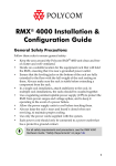
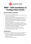
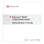
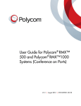
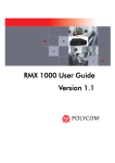
RMX® 4000
Installation Quick Start Guide for
RMX 4000
Basic Setup
Before installing the RMX 4000 and performing the Basic Setup, please read the
General Safety Precautions described in the Polycom RMX 4000 Hardware Guide.
For a detailed description of Unpacking and Rack mounting instructions, and
connecting a DC system, see the Polycom RMX 4000 Hardware Guide.
MPM+ Cards & LEDs
•
Two people are required to lift the MCU out of the box and when installing it in a
rack.
•
LAN 4, LAN 5 and the Serial ports are only for debugging and not for customer
use.
•
Do not remove the protective plastic caps from LAN 1, LAN 4 and LAN 5 ports.
Modifying the USB Key Settings
1
Insert the USB key provided with your system into the PC workstation and doubleclick LanConfigUtility.exe to start the utility.
During the first-time power-up the red ERR LED on the RMX’s front panel remains
ON until both the Management and IP Network Services have been defined.
3
Remove the USB key.
Enter the IP address of the RMX Control Unit and press Enter.
4
Fan Drawer
Enter POLYCOM.
Enter POLYCOM.
Fan &
Power
Status
LEDs
Fabric Switch
Module
(FSM 4000)
Logo Panel &
ESD Connector
Power Supply Drawers
and Status LEDs
LAN Connections to Port 2 on each RTM LAN
LAN Connections to Port 1 on RTM ISDN
Control Unit
(CNTL 4000) &
LEDs
Optional CPU
(Future)
Click Login.
2
Modify the parameters in the utility’s dialog box using the information supplied by
your network administrator.
3
Click OK.
4
Remove it from the PC.
5
Click to connect to Polycom
web site and register the
RMX.
Click Product Registration
and follow the on screen
instructions to obtain the
Product Activation Key.
First-time Power-up and Connection to MCU
1
Insert the USB key containing the modified IP addresses in the USB port on the
RMX’s back panel.
Enter or paste the Product
Activation Key obtained.
E1/T1 Connection to RTM ISDN
Signalling
Network
(Port 3)
6
Click OK.
Management
Network
(Port 2)
Shelf
Management
(Port 6 on
RTM IP)
Off/On
Switch
2
Power the RMX ON.
The parameters in the lan.cfg file are uploaded from the USB key to the RMX’s
memory and applied during the power-up sequence.
Power Cables
1
System power-up sequence may take up to five minutes.
DOC2567A
.
RMX® 4000
Modifying the Default IP Service
This section describes the definition of H.323 Network Service. For detailed description
of H.323, SIP and ISDN Network Service definitions, see the RMX Getting Started Guide,
“First Time Installation and Configuration”.
Select H.323 as the IP
Network Type.
Connecting to a Conference Directly or via Entry
Queue (EQ)
On the RMX 4000, IPv4 is the default protocol for setting the Network Service in the
Fast Configuration Wizard.
In the Fast Configuration Wizard, select Next to move from one window to another.
The RMX is shipped with pre-configured default conferencing entities that can be used
to dial in and start conferences. Default (Transit) Entry Queue ID: 1000, default Meeting
Room IDs: 1001, 1002, 1003, and 1004.
Change the default service
name if required.
Enter the address to be
used by IP endpoints when
dialing in to the MCU.
H.323 participants dial:
[MCU Prefix in Gatekeeper][Conference or Entry Queue ID/Name]
Enter the subnet mask of
the MCU.
1
5
6
Enter the name of the MCU
on the network.
Optional. Define the DNS
server properties:
• Registration mode
3
2
•
The name of the MCU
domain
•
The static IP address of
the primary DNS server
Select Specify to configure
the gatekeeper parameters.
Enter gatekeeper’s host
name or IP address.
Enter the string with which the
MCU registers itself with the
gatekeeper.
Enter the alias that identifies
the RMX’s Signaling Host
within the network. Up to five
aliases can be defined for
each RMX.
In the IP Network Service creation confirmation, click OK.
Optional. Modify the default
settings of the system flags
that define the general
system behavior such as the
number of digits in the
conference ID assigned by
the MCU.
These flags can be modified
later, if required, by selecting
the System Configuration
option from the Setup menu.
2
Optional. Select Specify to
define a DNS server.
H.323 Participants
4
Enter the IP address(es) of
the media card(s).
Enter the IP address of the
default router.
13 Create a new User with Administrator permissions and delete the default User
(POLYCOM). For system security reasons, only when this step is completed and if
there are no System Errors, the system is fully configured and the green RDY LED
on the CNTL module (on the RMX’s front panel) turns ON.
7
8
9
10
11
Click Save & Close.
In the Success Message box confirming successful configuration, click OK.
In the Reset Confirmation dialog box, click Yes.
In the Please wait for system reset message box, click OK.
System restart may take up to five minutes.
12 Refresh the browser periodically until the Login screen is displayed and Login.
In the Main Screen an MCU State indicator displays the time remaining until the
system start-up is complete.
For example, if the MCU prefix in gatekeeper is 925, you can dial to the default (Transit)
Entry Queue by entering 925 or 9251000 and be routed to Meeting Rooms by entering its
ID (i.e. 1001, 1002, 1003 or 1004). You can connect directly to one of the default Meeting
Rooms, by dialing its number, for example: 9251001.
Alternatively, you can use the Entry Queue or conference name to connect directly to
the conference. For example, if the conference name is Maple_Room, the participant can
dial: 925Maple_Room.
SIP Participants
The dialing string is composed of the conference routing name as registered with the
SIP server and domain name in the format: conference_name@domain_name
For example, if conference routing name is 1001, the string is [email protected].
ISDN and PSTN Participants
ISDN and PSTN participants can connect to conferences and Meeting Rooms directly or
via an Entry Queue by dialing one of the numbers (including the country and area code
if needed) assigned to the conference, Meeting Room or Entry Queue. When connecting
to an EQ they are routed to their conference according to the conference ID. For
example, if the assigned dial in number is 4045555, the ISDN/PSTN endpoint dials this
number with the appropriate area code (for example, 678) and country code (001).
Conference Control Using DTMF Codes
Operation
DTMF String
Operation
DTMF String
Mute My Line
*6
Request individual
assistance
*0
Unmute My Line
#6
Request assistance for
conference
00
Increase Broadcast Volume
*9
Increase Listening Volume
*76
Decrease Broadcast Volume
#9
Decrease Listening Volume
#76
Play Help Menu
*83
Change To Chairperson
*78
Start Click&View to modify
personal layout
**
Show Number of
Participants
*88
DOC2567A