1
VSX-1016TXV_KU.book.fm 1 ページ 2006年3月24日 金曜日 午後9時19分
AUDIO/VIDEO MULTI-CHANNEL
RECEIVER
VSX-1016TXV-K
Register your product at
www.pioneerelectronics.com (US)
www.pioneerelectronics.ca (Canada)
• Protect your new investment
The details of your purchase will be on file for reference in the event of an
insurance claim such as loss or theft.
• Receive free tips, updates and service bulletins on
your new product
• Improve product development
Your input helps us continue to design products that meet your needs.
• Receive a free Pioneer newsletter
Registered customers can opt in to receive a monthly newsletter.
Operating Instructions
VSX-1016TXV_KU.book.fm 2 ページ 2006年3月24日 金曜日 午後9時19分
CAUTION
– TO PREVENT ELECTRIC SHOCK, DO NOT USE THIS (POLARIZED) PLUG WITH AN EXTENSION
CORD.
RECEPTACLE OR OTHER OUTLET UNLESS THE BLADES CAN BE FULLY INSERTED TO PREVENT
BLADE EXPOSURE.
ATTENTION – POUR PREVENIR LES CHOCS ELECTRIQUES, NE PAS UTILISER CETTE FICHE POLARISEE AVEC UN
PROLONGATEUR, UNE PRISE DE COURANT, OU UNE AUTRE SORTIE DE COURANT, SAUF SI LES
LAMES PEUVENT ETRE INSEREES A FOND SANS EN LAISSER AUCUNE PARTIE A DECOUVERT.
D2-4-4-1_EF
WARNING – TO PREVENT FIRE OR SHOCK
HAZARD, DO NOT EXPOSE THIS
APPLIANCE TO RAIN OR MOISTURE.
D1-4-2-1_En
FEDERAL COMMUNICATIONS DECLARATION OF CONFORMITY
This device complies with part 15 of the FCC Rules. Operation is subject to the following two conditions: (1) This
device may not cause harmful interference, and (2) this device must accept any interference received, including
interference that may cause undesired operation.
Product Name:
AUDIO/VIDEO MULTI-CHANNEL RECEIVER
Model Number:
VSX-1016TXV-K
Responsible Party Name:
PIONEER ELECTRONICS SERVICE INC.
Address:
1925 E. DOMINGUEZ ST. LONG BEACH, CA 90801-1760, USA
Phone:
310–952–2915
IMPORTANT NOTICE – THE SERIAL NUMBER FOR THIS EQUIPMENT IS LOCATED IN THE REAR.
PLEASE WRITE THIS SERIAL NUMBER ON YOUR ENCLOSED WARRANTY CARD AND
D1-4-2-6-1_En
KEEP IN A SECURE AREA. THIS IS FOR YOUR SECURITY.
NOTE: This equipment has been tested and found to comply with the limits for a Class B digital device, pursuant to
Part 15 of the FCC Rules. These limits are designed to provide reasonable protection against harmful interference in
a residential installation. This equipment generates, uses, and can radiate radio frequency energy and, if not
installed and used in accordance with the instructions, may cause harmful interference to radio communications.
However, there is no guarantee that interference will not occur in a particular installation. If this equipment does
cause harmful interference to radio or television reception, which can be determined by turning the equipment off
and on, the user is encouraged to try to correct the interference by one or more of the following measures:
–
–
–
–
Reorient or relocate the receiving antenna.
Increase the separation between the equipment and receiver.
Connect the equipment into an outlet on a circuit different from that to which the receiver is connected.
D8-10-1-2_En
Consult the dealer or an experienced radio/TV technician for help.
This Class B digital apparatus complies with Canadian ICES-003.
Cet appareil numérique de la Classe B est conforme à la norme NMB-003 du Canada.
D8-10-1-3_EF
Information to User
Alteration or modifications carried out without appropriate authorization may invalidate the user’s right to operate
D8-10-2_En
the equipment.
CAUTION: This product satisfies FCC regulations when shielded cables and connectors are used to connect the
unit to other equipment. To prevent electromagnetic interference with electric appliances such as radios and
D8-10-3a_En
televisions, use shielded cables and connectors for connections.
WARNING: Handling the cord on this product or
cords associated with accessories sold with the
product will expose you to chemicals listed on
proposition 65 known to the State of California and
other governmental entities to cause cancer and
birth defect or other reproductive harm.
Wash hands after handling
D36-P4_A_En
For U.S. and Australia Model
C67-7-3_En
VSX-1016TXV_KU.book.fm 3 ページ 2006年3月24日 金曜日 午後9時19分
CAUTION
RISK OF ELECTRIC SHOCK
DO NOT OPEN
The lightning flash with arrowhead, within
an equilateral triangle, is intended to alert
the user to the presence of uninsulated
"dangerous voltage" within the product's
enclosure that may be of sufficient
magnitude to constitute a risk of electric
shock to persons.
CAUTION:
TO PREVENT THE RISK OF ELECTRIC
SHOCK, DO NOT REMOVE COVER (OR
BACK). NO USER-SERVICEABLE PARTS
INSIDE. REFER SERVICING TO QUALIFIED
SERVICE PERSONNEL.
The exclamation point within an equilateral
triangle is intended to alert the user to the
presence of important operating and
maintenance (servicing) instructions in the
literature accompanying the appliance.
D1-4-2-3_En
IMPORTANT SAFETY INSTRUCTIONS
READ INSTRUCTIONS — All the safety and
operating instructions should be read before the
product is operated.
RETAIN INSTRUCTIONS — The safety and
operating instructions should be retained for
future reference.
HEED WARNINGS — All warnings on the product
and in the operating instructions should be
adhered to.
FOLLOW INSTRUCTIONS — All operating and use
instructions should be followed.
CLEANING — The product should be cleaned only
with a polishing cloth or a soft dry cloth. Never
clean with furniture wax, benzine, insecticides
or other volatile liquids since they may corrode
the cabinet.
ATTACHMENTS — Do not use attachments not
recommended by the product manufacturer as
they may cause hazards.
WATER AND MOISTURE — Do not use this
product near water — for example, near a
bathtub, wash bowl, kitchen sink, or laundry
tub; in a wet basement; or near a swimming
pool; and the like.
ACCESSORIES — Do not place this product on an
unstable cart, stand, tripod, bracket, or table.
The product may fall, causing serious injury to a
child or adult, and serious damage to the
product. Use only with a cart, stand, tripod,
bracket, or table recommended by the
manufacturer, or sold with the product. Any
mounting of the product should follow the
manufacturer’s instructions, and should use a
mounting accessory recommended by the
manufacturer.
CART — A product and cart combination should be
moved with care. Quick stops, excessive force,
and uneven surfaces may cause the product
and cart combination to overturn.
VENTILATION — Slots and openings in the cabinet
are provided for ventilation and to ensure
reliable operation of the product and to protect
it from overheating, and these openings must
not be blocked or covered. The openings should
never be blocked by placing the product on a
bed, sofa, rug, or other similar surface. This
product should not be placed in a built-in
installation such as a bookcase or rack unless
proper ventilation is provided or the
manufacturer’s instructions have been adhered
to.
POWER SOURCES — This product should be
operated only from the type of power source
indicated on the marking label. If you are not
sure of the type of power supply to your home,
consult your product dealer or local power
company.
LOCATION – The appliance should be installed in a
stable location.
NONUSE PERIODS – The power cord of the
appliance should be unplugged from the outlet
when left un-used for a long period of time.
GROUNDING OR POLARIZATION
• If this product is equipped with a polarized
alternating current line plug (a plug having one
blade wider than the other), it will fit into the
outlet only one way. This is a safety feature. If
you are unable to insert the plug fully into the
outlet, try reversing the plug. If the plug should
still fail to fit, contact your electrician to replace
your obsolete outlet. Do not defeat the safety
purpose of the polarized plug.
• If this product is equipped with a three-wire
grounding type plug, a plug having a third
(grounding) pin, it will only fit into a grounding
type power outlet. This is a safety feature. If you
are unable to insert the plug into the outlet,
contact your electrician to replace your obsolete
outlet. Do not defeat the safety purpose of the
grounding type plug.
POWER-CORD PROTECTION — Power-supply
cords should be routed so that they are not likely
to be walked on or pinched by items placed
upon or against them, paying particular
attention to cords at plugs, convenience
receptacles, and the point where they exit from
the product.
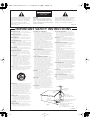
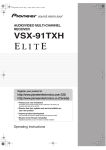
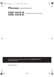
OUTDOOR ANTENNA GROUNDING — If an
outside antenna or cable system is connected to
the product, be sure the antenna or cable
system is grounded so as to provide some
protection against voltage surges and built-up
static charges. Article 810 of the National
Electrical Code, ANSI/NFPA 70, provides
information with regard to proper grounding of
the mast and supporting structure, grounding of
the lead-in wire to an antenna discharge unit,
size of grounding conductors, location of
antenna-discharge unit, connection to
grounding electrodes, and requirements for the
grounding electrode. See Figure A.
LIGHTNING — For added protection for this
product during a lightning storm, or when it is
left unattended and unused for long periods of
time, unplug it from the wall outlet and
disconnect the antenna or cable system. This
will prevent damage to the product due to
lightning and power-line surges.
POWER LINES — An outside antenna system
should not be located in the vicinity of overhead
power lines or other electric light or power
circuits, or where it can fall into such power
lines or circuits. When installing an outside
antenna system, extreme care should be taken
to keep from touching such power lines or
circuits as contact with them might be fatal.
OVERLOADING — Do not overload wall outlets,
extension cords, or integral convenience
receptacles as this can result in a risk of fire or
electric shock.
OBJECT AND LIQUID ENTRY — Never push
objects of any kind into this product through
openings as they may touch dangerous voltage
points or short-out parts that could result in a
fire or electric shock. Never spill liquid of any
kind on the product.
SERVICING — Do not attempt to service this
product yourself as opening or removing covers
may expose you to dangerous voltage or other
hazards. Refer all servicing to qualified service
personnel.
DAMAGE REQUIRING SERVICE — Unplug this
product from the wall outlet and refer servicing
to qualified service personnel under the
following conditions:
• When the power-supply cord or plug is
damaged.
• If liquid has been spilled, or objects have fallen
into the product.
• If the product has been exposed to rain or water.
• If the product does not operate normally by
following the operating instructions. Adjust only
those controls that are covered by the operating
instructions as an improper adjustment of other
controls may result in damage and will often
require extensive work by a qualified technician
to restore the product to its normal operation.
• If the product has been dropped or damaged in
any way.
• When the product exhibits a distinct change in
performance — this indicates a need for service.
REPLACEMENT PARTS — When replacement parts
are required, be sure the service technician has
used replacement parts specified by the
manufacturer or have the same characteristics
as the original part. Unauthorized substitutions
may result in fire, electric shock, or other
hazards.
SAFETY CHECK — Upon completion of any service
or repairs to this product, ask the service
technician to perform safety checks to
determine that the product is in proper
operating condition.
WALL OR CEILING MOUNTING — The product
should not be mounted to a wall or ceiling.
HEAT — The product should be situated away from
heat sources such as radiators, heat registers,
stoves, or other products (including amplifiers)
that produce heat.
ANTENNA
LEAD IN
WIRE
GROUND
CLAMP
ANTENNA
DISCHARGE UNIT
(NEC SECTION 810-20)
ELECTRIC
SERVICE
EQUIPMENT
Fig. A
GROUNDING CONDUCTORS
(NEC SECTION 810-21)
GROUND CLAMPS
POWER SERVICE GROUNDING
ELECTRODE SYSTEM
(NEC ART 250, PART H)
NEC — NATIONAL ELECTRICAL CODE
D1-4-2-2_En
VSX-1016TXV_KU.book.fm 4 ページ 2006年3月24日 金曜日 午後9時19分
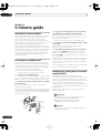
Thank you for buying this Pioneer product. Please read through these operating instructions so you will know how to operate
your model properly. After you have finished reading the instructions, put them away in a safe place for future reference.
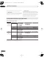
Contents
01 Before you start
05 Listening to your system
Features . . . . . . . . . . . . . . . . . . . . . . . . . . . . . . . . . . . . . . 6
Checking what’s in the box . . . . . . . . . . . . . . . . . . . . . . . 6
Ventilation. . . . . . . . . . . . . . . . . . . . . . . . . . . . . . . . . . . . . 7
Installing the receiver . . . . . . . . . . . . . . . . . . . . . . . . . . . 7
Loading the batteries. . . . . . . . . . . . . . . . . . . . . . . . . . . . 7
Auto playback . . . . . . . . . . . . . . . . . . . . . . . . . . . . . . . .
Listening in surround sound . . . . . . . . . . . . . . . . . . . .
Standard surround sound . . . . . . . . . . . . . . . . . . . . .
Using the Home THX modes . . . . . . . . . . . . . . . . . . .
Using the Advanced surround effects . . . . . . . . . . .
Setting the effect options. . . . . . . . . . . . . . . . . . . . . .
Listening in stereo. . . . . . . . . . . . . . . . . . . . . . . . . . . . .
Listening with Acoustic Calibration EQ . . . . . . . . . . .
Choosing the input signal . . . . . . . . . . . . . . . . . . . . . .
Using surround back channel processing . . . . . . . . .
Using the Virtual Surround Back mode . . . . . . . . . .
Using Midnight and Loudness. . . . . . . . . . . . . . . . . . .
Using the Sound Retriever . . . . . . . . . . . . . . . . . . . . . .
Enhancing dialog . . . . . . . . . . . . . . . . . . . . . . . . . . . . .
Using the tone controls . . . . . . . . . . . . . . . . . . . . . . . .
02 5 minute guide
Introduction to home theater . . . . . . . . . . . . . . . . . . . . . 8
Listening to Surround Sound . . . . . . . . . . . . . . . . . . . . . 8
Automatically setting up for surround sound
(MCACC) . . . . . . . . . . . . . . . . . . . . . . . . . . . . . . . . . . . . . . 8
Problems when using the Auto MCACC Setup . . . . 10
Playing a source. . . . . . . . . . . . . . . . . . . . . . . . . . . . . . . 10
Better sound using Basic Phase Control . . . . . . . . . . 10
03 Connecting your equipment
Rear panel . . . . . . . . . . . . . . . . . . . . . . . . . . . . . . . . . . . 11
When making cable connections. . . . . . . . . . . . . . . . . 12
About the video converter . . . . . . . . . . . . . . . . . . . . . . . 12
Connecting your TV and DVD player . . . . . . . . . . . . . . 13
Connecting a satellite/cable receiver or other
set-top box . . . . . . . . . . . . . . . . . . . . . . . . . . . . . . . . . . . 13
Connecting a DVD/HDD recorder, VCR and
other video sources . . . . . . . . . . . . . . . . . . . . . . . . . . . . 14
Using the component video jacks . . . . . . . . . . . . . . . . 14
Connecting digital audio sources . . . . . . . . . . . . . . . . 15
About the WMA9 Pro decoder . . . . . . . . . . . . . . . . . . 16
Connecting analog audio sources . . . . . . . . . . . . . . . . 16
Connecting a component to the front panel
inputs . . . . . . . . . . . . . . . . . . . . . . . . . . . . . . . . . . . . . . . 16
Installing your speaker system . . . . . . . . . . . . . . . . . . . 17
Connecting the speakers . . . . . . . . . . . . . . . . . . . . . . 17
Placing the speakers. . . . . . . . . . . . . . . . . . . . . . . . . . 18
THX speaker system setup . . . . . . . . . . . . . . . . . . . . . 19
Connecting antennas . . . . . . . . . . . . . . . . . . . . . . . . . . 19
Connecting external antennas . . . . . . . . . . . . . . . . . . 20
Plugging in the receiver . . . . . . . . . . . . . . . . . . . . . . . . 20
AC outlet . . . . . . . . . . . . . . . . . . . . . . . . . . . . . . . . . . . . . 20
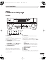
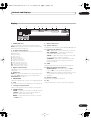
04 Controls and displays
Front panel . . . . . . . . . . . . . . . . . . . . . . . . . . . . . . . . . . . 21
Operating range of remote control unit . . . . . . . . . . 22
Display . . . . . . . . . . . . . . . . . . . . . . . . . . . . . . . . . . . . . . 23
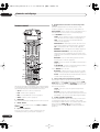
Remote control. . . . . . . . . . . . . . . . . . . . . . . . . . . . . . . . 24
4
En
26
26
26
27
27
27
28
28
29
29
29
30
30
30
30
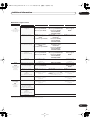
06 Using the tuner
Listening to the radio . . . . . . . . . . . . . . . . . . . . . . . . . .
Improving FM stereo sound. . . . . . . . . . . . . . . . . . . .
Tuning directly to a station . . . . . . . . . . . . . . . . . . . .
Saving station presets . . . . . . . . . . . . . . . . . . . . . . . . .
Naming station presets . . . . . . . . . . . . . . . . . . . . . . .
Listening to station presets . . . . . . . . . . . . . . . . . . . .
31
31
31
31
32
32
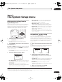
07 The System Setup menu
Making receiver settings from the System Setup
menu . . . . . . . . . . . . . . . . . . . . . . . . . . . . . . . . . . . . . . .
Surround back speaker setting . . . . . . . . . . . . . . . . . .
Manual MCACC setup . . . . . . . . . . . . . . . . . . . . . . . . .
Fine Channel Level . . . . . . . . . . . . . . . . . . . . . . . . . . .
Fine Speaker Distance . . . . . . . . . . . . . . . . . . . . . . . .
Acoustic Calibration EQ. . . . . . . . . . . . . . . . . . . . . . .
Manual speaker setup . . . . . . . . . . . . . . . . . . . . . . . . .
Speaker Setting . . . . . . . . . . . . . . . . . . . . . . . . . . . . .
Crossover Network . . . . . . . . . . . . . . . . . . . . . . . . . . .
Channel Level . . . . . . . . . . . . . . . . . . . . . . . . . . . . . . .
Speaker Distance . . . . . . . . . . . . . . . . . . . . . . . . . . . .
THX Audio Setting . . . . . . . . . . . . . . . . . . . . . . . . . . .
THX Speaker Setup. . . . . . . . . . . . . . . . . . . . . . . . . . .
33
33
34
34
35
35
37
37
38
38
39
39
39
VSX-80TXV_81TXV_TOC.fm 5 ページ 2006年4月4日 火曜日 午後6時10分
08 Other connections
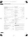
12 Additional information
Using XM Radio . . . . . . . . . . . . . . . . . . . . . . . . . . . . . . . 40
Connecting your XM Radio receiver . . . . . . . . . . . . . 40
Listening to XM Radio. . . . . . . . . . . . . . . . . . . . . . . . . 40
Using XM HD Surround . . . . . . . . . . . . . . . . . . . . . . . 41
Saving channel presets . . . . . . . . . . . . . . . . . . . . . . . 41
Connecting using HDMI . . . . . . . . . . . . . . . . . . . . . . . . 41
About HDMI . . . . . . . . . . . . . . . . . . . . . . . . . . . . . . . . . . 42
Connecting the multichannel analog inputs . . . . . . . 42
Selecting the multichannel analog inputs . . . . . . . . 42
Second Zone speaker B setup . . . . . . . . . . . . . . . . . . . 42
Switching the speaker system . . . . . . . . . . . . . . . . . . 43
Bi-amping your front speakers . . . . . . . . . . . . . . . . . . . 43
Bi-wiring your speakers. . . . . . . . . . . . . . . . . . . . . . . . . 44
Connecting additional amplifiers . . . . . . . . . . . . . . . . . 44
Using this receiver with a Pioneer plasma display. . . 44
Using the SR+ mode with a Pioneer plasma
display. . . . . . . . . . . . . . . . . . . . . . . . . . . . . . . . . . . . . . . 45
Troubleshooting . . . . . . . . . . . . . . . . . . . . . . . . . . . . . .
Power. . . . . . . . . . . . . . . . . . . . . . . . . . . . . . . . . . . . . .
No sound. . . . . . . . . . . . . . . . . . . . . . . . . . . . . . . . . . .
Other audio problems . . . . . . . . . . . . . . . . . . . . . . . .
Video . . . . . . . . . . . . . . . . . . . . . . . . . . . . . . . . . . . . . .
Settings . . . . . . . . . . . . . . . . . . . . . . . . . . . . . . . . . . . .
Display. . . . . . . . . . . . . . . . . . . . . . . . . . . . . . . . . . . . .
Remote control . . . . . . . . . . . . . . . . . . . . . . . . . . . . . .
HDMI . . . . . . . . . . . . . . . . . . . . . . . . . . . . . . . . . . . . . .
XM radio messages . . . . . . . . . . . . . . . . . . . . . . . . . .
Surround sound formats . . . . . . . . . . . . . . . . . . . . . . .
Dolby . . . . . . . . . . . . . . . . . . . . . . . . . . . . . . . . . . . . . .
DTS . . . . . . . . . . . . . . . . . . . . . . . . . . . . . . . . . . . . . . .
Windows Media® Audio 9 Professional . . . . . . . . .
About THX . . . . . . . . . . . . . . . . . . . . . . . . . . . . . . . . . . .
Listening modes with different input signal
formats. . . . . . . . . . . . . . . . . . . . . . . . . . . . . . . . . . . . . .
Specifications . . . . . . . . . . . . . . . . . . . . . . . . . . . . . . . .
Cleaning the unit. . . . . . . . . . . . . . . . . . . . . . . . . . . . . .
09 Other Settings
The Input Assign menu . . . . . . . . . . . . . . . . . . . . . . . . . 46
The Other Setup menu . . . . . . . . . . . . . . . . . . . . . . . . . 47
Dynamic Range Control Setup . . . . . . . . . . . . . . . . . 47
Dual Mono Setup . . . . . . . . . . . . . . . . . . . . . . . . . . . . 48
LFE Attenuator Setup . . . . . . . . . . . . . . . . . . . . . . . . . 48
SR+ Setup for Pioneer plasma displays. . . . . . . . . . 48
Video Converter Setup . . . . . . . . . . . . . . . . . . . . . . . . 48
57
57
57
58
59
59
60
60
61
61
62
62
62
62
63
64
66
66
This product is for general household purposes. Any
failure due to use for other than household purposes
(such as long-term use for business purposes in a
restaurant or use in a car or ship) and which requires
repair will be charged for even during the warranty
K041_En
period.
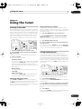
10 Using other functions
Making an audio or a video recording . . . . . . . . . . . . . 49
Reducing the level of an analog signal . . . . . . . . . . . . 49
Watching video and audio sources independently . . 49
Using the sleep timer . . . . . . . . . . . . . . . . . . . . . . . . . . 50
Dimming the display . . . . . . . . . . . . . . . . . . . . . . . . . . . 50
Switching the speaker impedance. . . . . . . . . . . . . . . . 50
Resetting the system . . . . . . . . . . . . . . . . . . . . . . . . . . . 50
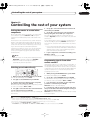
11 Controlling the rest of your system
Setting the remote to control other components . . . . 51
Selecting preset codes directly . . . . . . . . . . . . . . . . . . 51
Programming signals from other remote controls. . . 51
Erasing one of the remote control button settings. . . 52
Resetting the remote control presets . . . . . . . . . . . . . 52
Confirming preset codes. . . . . . . . . . . . . . . . . . . . . . . . 52
Direct function . . . . . . . . . . . . . . . . . . . . . . . . . . . . . . . . 53
Multi Operation and System Off. . . . . . . . . . . . . . . . . . 53
Programming a multi-operation or a shutdown
sequence . . . . . . . . . . . . . . . . . . . . . . . . . . . . . . . . . . . 53
Using multi operations . . . . . . . . . . . . . . . . . . . . . . . . 54
Using System off . . . . . . . . . . . . . . . . . . . . . . . . . . . . . 54
Controls for TVs . . . . . . . . . . . . . . . . . . . . . . . . . . . . . . . 55
Controls for other components . . . . . . . . . . . . . . . . . . 55
Operating other Pioneer components with this
unit’s sensor. . . . . . . . . . . . . . . . . . . . . . . . . . . . . . . . . . 56
5
En
VSX-1016TXV_KU.book.fm 6 ページ 2006年3月24日 金曜日 午後9時19分
01
Before you start
Chapter 1:
Before you start
Features
• Advanced Direct Energy design
This receiver offers a new advancement in discrete
design unique to Pioneer for high-power drivability, low
distortion and stable imaging. Through symmetrical
placement of power amplification units, this receiver
generates equal amplifier power to all channels,
eliminating the possibility of one channel dominating a
particular sound field.
• Easy setup using Multichannel Acoustic
Calibration (MCACC)
Setting up for home theater sound is as easy as
connecting your speakers, a DVD player or other source,
and your TV. The Auto Surround Setup provides a quick
but accurate surround sound setup, while for complete
surround sound control you still have access to the full
range of surround sound settings.
• THX Select2 certified design
This receiver bears the THX Select2 logo, which means it
has passed a rigorous series of quality and performance
tests covering every aspect of the product. This includes
testing of pre-amplifier and power amplifier performance
and operation, and hundreds of other parameters in both
the digital and analog domain, making your home
theater experience as faithful as possible to what the
director intended.
• Dolby Digital and DTS decoding, including Dolby
Digital EX, Dolby Pro Logic IIx, DTS 96/24 and DTS-ES
Dolby Digital and DTS decoding brings theater sound
right into your home with up to six channels of surround
sound, including a special LFE (Low Frequency Effects)
channel for deep, realistic sound effects.
The built-in Dolby Pro Logic IIx and DTS Neo:6 decoders
not only provide full surround sound decoding for Dolby
Surround sources, but will also generate convincing
surround sound for any stereo source.
Also, with the addition of a surround back speaker, you
can take advantage of the built-in Dolby Digital EX and
DTS-ES decoders for six-channel surround sound.
• Phase correction
Based on Pioneer’s unique Phase Control Technology,
the Basic Phase Control feature incorporated into this
receiver’s design provides coherent sound reproduction
through the use of phase matching for an optimal sound
image at your listening position.
6
En
• Sound Retriever
The Sound Retriever feature employs new DSP
technology that helps bring CD quality sound back to
WMA, MP3 and MPEG-4 AAC audio files by restoring
sound pressure and smoothing jagged artifacts left over
after compression.
• HDMI compatibility
This receiver is compatible with the HDMI digital video
format, providing you high-definition digital video and
digital audio via a single cable.
• Built-in video converter
The built-in video converter provides output of all analog
video signals to your TV or monitor (regardless of the type
of connection), allowing you to connect components
using component, S-video, and composite video
connections as you like.
• XM Ready
With the new XM Radio terminal, you’ll be up and
running in no time, now that this receiver’s enhanced
compatibility makes XM HD Surround playback and onscreen control of XM Radio an added possibility.
• Easy-to-use LCD remote control
The remote control gives you not only complete control
over every function of this receiver, but also over the main
functions for other components in your home theater
system. Using a system of preset codes, you can
program the remote to operate a wide range of other
equipment.
Checking what’s in the box
Please check that you've received the following supplied
accessories:
• Setup microphone (cable: 16.4 ft.)
• Remote control unit
• AA/IEC R6P dry cell batteries x2
• AM loop antenna
• FM wire antenna
• Warranty card
• These operating instructions
VSX-1016TXV_KU.book.fm 7 ページ 2006年3月24日 金曜日 午後9時19分
Before you start
01
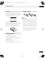
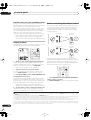
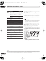
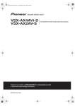
Ventilation
Loading the batteries
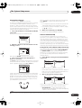
When installing this unit, make sure to leave space
around the unit for ventilation to improve heat dispersal
(at least 8 in. (20 cm) at the top). If not enough space is
provided between the unit and walls or other equipment,
heat will build up inside, interfering with performance
and/or causing malfunctions.
8 inches
(20 cm)
Receiver
Caution
Incorrect use of batteries may result in such hazards as
leakage and bursting. Observe the following precautions:
• Never use new and old batteries together.
Slot and openings in the cabinet are provided for
ventilation and to protect the equipment from
overheating. To prevent fire hazard, do not place anything
directly on top of the unit, make sure the openings are
never blocked or covered with items (such as
newspapers, table-cloths and curtains), and do not
operate the equipment on thick carpet or a bed.
• Insert the plus and minus sides of the batteries
properly according to the marks in the battery case.
• Batteries with the same shape may have different
voltages. Do not use different batteries together.
• When disposing of used batteries, please comply
with governmental regulations or environmental
public instruction’s rules that apply in your country or
area.
• Do not use or store batteries in direct sunlight or
other excessively hot place, such as inside a car or
near a heater. This can cause batteries to leak,
overheat, explode or catch fire. It can also reduce the
life or performance of batteries.
DOWN
DOWN
Installing the receiver
• When installing this unit, make sure to put it on a
level and stable surface.
Don’t install it on the following places:
– on a color TV (the screen may distort)
– near a cassette deck (or close to a device that gives off
a magnetic field). This may interfere with the sound.
– in direct sunlight
– in damp or wet areas
– in extremely hot or cold areas
– in places where there is vibration or other movement
– in places that are very dusty
– in places that have hot fumes or oils (such as a kitchen)
7
En
VSX-1016TXV_KU.book.fm 8 ページ 2006年3月24日 金曜日 午後9時19分
02
5 minute guide
Chapter 2:
5 minute guide
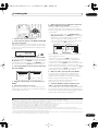
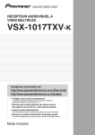
Introduction to home theater
Home theater refers to the use of multiple audio tracks to
create a surround sound effect, making you feel like
you're in the middle of the action or concert. The
surround sound you get from a home theater system
depends not only on your speaker setup, but also on the
source and the sound settings of the receiver.
This receiver will automatically decode multichannel
Dolby Digital, DTS, or Dolby Surround sources according
to your speaker setup. In most cases, you won’t have to
make changes for realistic surround sound, but other
possibilities (like listening to a CD with multichannel
surround sound) are explained in Listening to your
system on page 26.
Listening to Surround Sound
This receiver was designed with the easiest possible
setup in mind, so with the following quick setup guide,
you should have your system hooked up for surround
sound in no time at all. In most cases, you can simply
leave the receiver in the default settings.
• Be sure to complete all connections before
connecting this unit to an AC power source.
1 Connect your TV and DVD player.
See Connecting your TV and DVD player on page 13 to do
this. For surround sound, you’ll want to hook up using a
digital connection from the DVD player to the receiver.
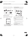
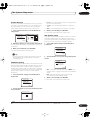
2 Connect your speakers and place them for optimal
surround sound.
Connect your speakers as shown in Installing your
speaker system on page 17.
Where you place the speakers will have a big effect on the
sound. Place your speakers as shown below for the best
surround sound effect. Also see Placing the speakers on
page 18 for more on this.
Center (C)
Front
Left (L)
• Set the subwoofer volume to a comfortable level.
4 Use the on-screen automatic MCACC setup to set up
your system.
See Automatically setting up for surround sound
(MCACC) below for more on this.
5 Play a DVD, and adjust the volume to your liking.
Make sure that DVD/LD is showing in the receiver’s
display, indicating that the DVD input is selected. If it
isn’t, press DVD on the remote control to set the receiver
to the DVD input.
In addition to the basic playback explained in Playing a
source on page 10, there are several other sound options
you can select. See Listening to your system on page 26
for more on this.
See also Making receiver settings from the System Setup
menu on page 33 for more setup options.
Automatically setting up for surround
sound (MCACC)
The Auto MCACC Setup measures the acoustic
characteristics of your listening area, taking into account
ambient noise, speaker size and distance, and tests for
both channel delay and channel level. After you have set
up the microphone provided with your system, the
receiver uses the information from a series of test tones
to optimize the speaker settings and equalization for your
particular room.
Make sure you do this before moving on to Playing a
source on page 10.
Important
• Make sure the microphone and speakers are not
moved during the Auto MCACC Setup.
Front
Right (R)
Subwoofer (SW)
3 Plug in the receiver and switch it on, followed by
your DVD player, your subwoofer and the TV.
Make sure you’ve set the video input on your TV to this
receiver. Check the manual that came with the TV if you
don’t know how to do this.
Surround
Right (SR)
• Before using the Auto MCACC Setup the
headphones should be disconnected.
Caution
Surround
Back
Right (SBR)
Listening
position
Surround
Left (SL)
Surround
Back Left (SBL)
8
En
• The test tones used in the Auto MCACC Setup are
output at high volume.
VSX-1016TXV_KU.book.fm 9 ページ 2006年3月24日 金曜日 午後9時19分
5 minute guide
02
DIALOG E
PHASE
S.RETRIEVER
SYSTEM OFF
INPUT
RECEIVER SELECT
SOURCE
D.ACCESS
CLASS
+10
DISC
ENTER
MENU
TOP MENU
TUNE
DTV MENU
ST
ST
ENTER
SETUP
GUIDE
CATEGORY
DVR 2
DVD
TV
CD
CD-R
BAND
TV CONTROL
DVR1
TV CTRL
TV VOL
XM RADIO
1
T.EDIT
RETURN
TUNE
TUNER
INPUT
SELECT
TV CH
VOL
RECEIVER
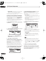
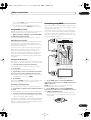
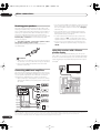
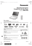
Switch on the receiver and your TV.
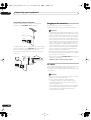
2 Connect the microphone to the MCACC SETUP MIC
jack on the front panel.
Place the microphone so that it’s about ear level at your
normal listening position (use a tripod if possible). Make
sure there are no obstacles between the speakers and
the microphone.
S - VIDEO
VIDEO
PHONES
SYSTEM
SETUP
RETURN
TONE
TUNING/
STATION
TUNER
EDIT
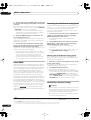
7 Wait for the test tones to finish then confirm the
speaker configuration in the OSD.
A progress report is displayed on-screen while the
receiver outputs test tones to determine the speakers
present in your setup. Try to be as quiet as possible while
it’s doing this.4
VIDEO/GAME INPUT
L AUDIO R
DIGITAL IN
• With error messages (such as Ambient Noise or
Microphone Check) select RETRY after checking for
ambient noise (see Problems when using the Auto
MCACC Setup below) and verifying the mic
connection. If there doesn’t seem to be a problem,
you can simply select OK and continue.
2.Auto MCACC
2.Auto MCACC
Now Analyzing
Environment Check
Ambient Noise
Microphone
Speaker YES/NO
Check!
[ OK ]
[ OK ]
[ OK ]
:Cancel
MCACC
SETUP MIC
Front
Center
Surround
SB
SUB W.
[
[
[
[
[
YES
YES
YES
Yx2
YES
]
]
]
]
]
OK
:Cancel
SPEAKERS
MULTI JOG
3 Press RECEIVER on the remote, then press SETUP.
An on-screen display (OSD) appears on your TV. Use the
/// buttons and ENTER to navigate through the
screens and select menu items. Press RETURN to exit
the current menu. Press SETUP at any time to cancel.1
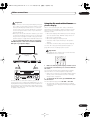
4 Select ‘Auto MCACC’ from the System Setup menu
then press ENTER.2
System Setup
2. Auto MCACC
1.Surr Back System
2.Auto MCACC
3.Manual MCACC
4.Manual SP Setup
5.Input Assign
6.Other Setup
: Exit
Surr Back System
Normal (SB)
Enter : Start
]
: Cancel
5 Make sure ‘Normal (SB)’ is selected then press
ENTER.3
6 Follow the instructions on-screen.
Make sure the microphone is connected, and if you’re
using a subwoofer, make sure it is switched on and set to
a comfortable volume level.
The configuration shown on-screen should reflect the
actual speakers you have.5
If you see an error message (ERR) in the right side
column (or the speaker configuration displayed isn’t
correct), there may be a problem with the speaker
connection. If selecting RETRY doesn’t work, turn off the
power and check the speaker connections. If there
doesn’t seem to be a problem, you can simply use /
to select the speaker and / to change the setting
(and number for surround back) and continue.
8 Make sure ‘OK’ is selected, then press ENTER.
A progress report is displayed on-screen while the
receiver outputs more test tones to determine the
optimum receiver settings for channel level, speaker
distance, and Acoustic Calibration EQ.
Again, try to be as quiet as possible while this is
happening. It may take 3 to 8 minutes.
9 The Auto MCACC Setup has finished! Select
‘SKIP’ to go back to the System Setup menu.
The settings made in the Auto MCACC Setup should give
you excellent surround sound from your system, but it is
also possible to adjust these settings manually using the
System Setup menu (starting on page 33).6
Note
1 • If you cancel the Auto MCACC Setup, or leave an error message for over three minutes, the screen saver will appear.
• The OSD will not appear if you have connected using the HDMI output to your TV. Use component, S-video, or composite connections for system setup.
2 You can’t use the System Setup menu when the XM Radio input source is selected.
3 • If you are planning on bi-amping your front speakers, or setting up a separate speaker system in another room, read through Surround back speaker
setting on page 33 and make sure to connect your speakers as necessary before continuing to step 6.
• If you have THX-certified speakers, make sure YES is selected in THX Speaker Setup on page 39.
4 Do not adjust the volume during the test tones. This may result in incorrect speaker settings.
5 If you’re using the front panel display, the diagram in Listening to Surround Sound above indicates (in bold) how each speaker is displayed.
6 • Depending on the characteristics of your room, sometimes identical speakers with cone sizes of around 5 inches will end up with different size settings.
You can correct the setting manually using the Manual speaker setup on page 37.
• The subwoofer distance setting may be farther than the actual distance from the listening position. This setting should be accurate (taking delay and
room characteristics into account) and generally does not need to be changed.
9
En
VSX-1016TXV_KU.book.fm 10 ページ 2006年3月24日 金曜日 午後9時19分
02
5 minute guide
Problems when using the Auto MCACC Setup
If the room environment is not optimal for the Auto
MCACC Setup (too much background noise, echo off the
walls, obstacles blocking the speakers from the
microphone) the final settings may be incorrect. Check
for household appliances (air conditioner, fridge, fan,
etc.), that may be affecting the environment and switch
them off if necessary. If there are any instructions
showing in the front panel display, please follow them.
• Some older TVs may interfere with the operation of
the microphone. If this seems to be happening,
switch off the TV when doing the Auto MCACC Setup.
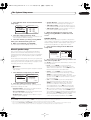
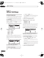
Better sound using Basic Phase Control
This receiver’s Basic Phase Control feature uses phase
correction measures to make sure your sound source
arrives at the listening position in phase, preventing
unwanted distortion and/or coloring of the sound (see
illustration below).
?
C
O
N
T
O
F
F
Playing a source
Sound
source
Here are the basic instructions for playing a source (such
as a DVD disc) with your home theater system.
VOL
P
H
A
S
E
MUTE
C
O
N
T
GUIDE
TV CONTROL
SYSTEM OFF
INPUT
RECEIVER SELECT
SOURCE
TV VOL
DTV ON/OFF
INPUT
SELECT
REC
DISP
DVR 2
TV
CD
CD-R
DVR1
TV CTRL
DTV INFO
REC STOP JUKEBOX
MPX
AUDIO SUBTITLE
DVD
TV CH
STATUS SIGNAL SEL
HDD
DVD
CH
CH
SBch
RECEIVER
MULTI OPE
THX
O
N
Subwoofer
Front speaker
Sound
source
Listening
position
Subwoofer
STEREO
XM RADIO
TUNER
Listening
position
Front speaker
P
H
A
S
E
STANDARD ADV.SURR
1 Switch on your system components and receiver.
Start by switching on the playback component (for
example a DVD player), your TV1 and subwoofer (if you
have one), then the receiver (press RECEIVER).
• Make sure the setup mic is disconnected.
Phase Control technology provides coherent sound
reproduction through the use of phase matching4 for an
optimal sound image at your listening position. The
default setting is on and we recommend leaving Phase
Control switched on for all sound sources.
DVR 2
DVR1
TV CTRL
XM RADIO
CD
2 Select the input source you want to play.
You can use the input source buttons on the remote
control, INPUT SELECT, or the front panel controls.2
3 Press AUTO SURR to select ‘AUTO SURROUND’ and
start playback of the source.3
If you’re playing a Dolby Digital or DTS surround sound
DVD disc, you should hear surround sound. If you are
playing a stereo source, you will only hear sound from the
front left/right speakers in the default listening mode.
• See also Listening to your system on page 26 for
information on different ways of listening to sources.
TV
DVD
D.ACCESS
CD-R
TUNER
RECEIVER
ANALOG
ATT
SLEEP
SB ch
SR+
DIMMER
MIDNIGHT/
LOUDNESS
DIALOG E
PHASE
S.RETRIEVER
+10
CLASS
DISC
ENTER
• Press RECEIVER then PHASE (PHASE CONTROL) to
switch on phase correction.
The PHASE CONTROL indicator on the front panel lights.
4 Use the volume control to adjust the volume level.
Turn down the volume of your TV so that all sound is
coming from the speakers connected to this receiver.
Note
1 Make sure that the TV’s video input is set to this receiver. (For example, if you connected this receiver to the VIDEO 1 jacks on your TV, make sure that
the VIDEO 1 input is now selected.)
2 If you need to manually switch the input signal type press SIGNAL SEL (page 29).
3 • You may need to check the digital audio output settings on your DVD player or digital satellite receiver. It should be set to output Dolby Digital, DTS
and 88.2 kHz / 96 kHz PCM (2 channel) audio, and if there is an MPEG audio option, set this to convert the MPEG audio to PCM.
• Depending on your DVD player or source discs, you may only get digital 2 channel stereo and analog sound. In this case, the receiver must be set to
a multichannel listening mode (see Listening in surround sound on page 26 if you need to do this) if you want multichannel surround sound.
4 Phase matching is a very important factor in achieving proper sound reproduction. If two waveforms are 'in phase', they crest and trough together, resulting in increased amplitude, clarity and presence of the sound signal. If a crest of a wave meets a trough (as shown in the upper section of the diagram
above) then the sound will be 'out of phase' and an unreliable sound image will be produced.
10
En
VSX-1016TXV_KU.book.fm 11 ページ 2006年3月24日 金曜日 午後9時19分
Connecting your equipment
03
Chapter 3
Connecting your equipment
This receiver provides you with many connection possibilities, but it doesn’t have to be difficult. This page explains the
kinds of components you can connect to make up your home theater system.
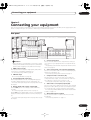
Rear panel
14 OUTLET
PRE OUT
CENTER
CENTE
P
P
L
L
R
RROUND
D
CK
SWITCHED 100 W(0.8 A) MAX
13
A
IN
OUT
IN
DVR/VCR1
OUT
IN
DVR/VCR2
Caution
• Before making or changing the connections, switch
off the power and disconnect the power cord from the
power outlet. Plugging in should be the final step.
1 HDMI connectors (x3)
Two inputs and one output for high-quality audio/video
connection to compatible HDMI devices.
Connecting using HDMI on page 41.
2
XM Radio input
See Using XM Radio on page 40.
3 Coaxial digital audio inputs (x2)
Use for digital audio sources, including DVD players/
recorders, digital satellite receivers, CD players, etc.
See also The Input Assign menu on page 46 to assign
the inputs.
4 Optical digital audio output / input(s) (x4)
Use the OUT jack for recording to a CD or MiniDisc
recorder.
Connecting digital audio sources on page 15.
Use the IN jacks for digital audio sources, including DVD
players/recorders, digital satellite receivers, CD players,
etc.
See also The Input Assign menu on page 46 to assign
the inputs.
5 Control input/output
Use to connect other Pioneer components so that you
can control all your equipment from a single IR remote
sensor.
Operating other Pioneer components with this unit’s
sensor on page 56.
6 Stereo analog audio source inputs/(outputs) (x3)
Use for connection to audio sources such as CD players,
tape decks, turntables, etc.
Connecting analog audio sources on page 16.
7 Component video connections (x4)
Use the inputs to connect any video source that has
component video output, such as a DVD recorder. Use
the output for connection to a monitor or TV.
Using the component video jacks on page 14.
8 Audio/video source inputs/(outputs) (x6)
Use for connection to audio/visual sources, such as DVD
players/recorders, VCRs, etc. Each set of inputs has jacks
for composite video, S-video and stereo analog audio.
Connecting a DVD/HDD recorder, VCR and other video
sources on page 14.
9 AM and FM antenna terminals
Use to connect indoor or outdoor antennas for radio
broadcasts.
Connecting antennas on page 19.
11
En
VSX-1016TXV_KU.book.fm 12 ページ 2006年3月24日 金曜日 午後9時19分
03
Connecting your equipment
10 Multichannel pre-amplifier outputs
Use to connect separate amplifiers for front, center,
surround, surround back and subwoofer channels.
Connecting additional amplifiers on page 44 (see also
Installing your speaker system on page 17 for powered
subwoofer connection).
11 Composite and S-video monitor outputs
Use to connect monitors and TVs.
Connecting your TV and DVD player on page 13.
12 Multichannel analog audio inputs
7.1 channel inputs for connection to a DVD player with
multichannel analog outputs.
Connecting the multichannel analog inputs on
page 42.
13 Speaker terminals
Use for connection to the main front, center, surround
and surround back speakers.
Installing your speaker system on page 17.
14 Switched AC power outlet (100 W/0.8 A max.)
Use to power another component in the system. Power to
the outlet switches on and off with the receiver.
AC outlet on page 20.
About the video converter
When the video converter is enabled, all analog video
sources are output through all of the MONITOR VIDEO
OUT jacks (HDMI and high-definition progressive
component video cannot be converted).1 See Video
Converter Setup on page 48 to switch the video converter
on or off.
If several video components are assigned to the same
input function (see The Input Assign menu on page 46),
the converter gives priority to component, S-video, then
composite (in that order).
• For optimal video performance, THX recommends
switching video conversion (in Video Converter Setup
on page 48) OFF.
This product incorporates copyright protection technology
that is protected by U.S. patents and other intellectual
property rights. Use of this copyright protection
technology must be authorized by Macrovision
Corporation, and is intended for home and other limited
consumer uses only unless otherwise authorized by
Macrovision. Reverse engineering or disassembly is
prohibited.
When making cable connections
• To avoid hum, do not lay connected cables over the
top of the receiver.
• When connecting optical cables, be careful when
inserting the plug not to damage the shutter
protecting the optical socket.
• When storing optical cable, coil loosely. The cable
may be damaged if bent around sharp corners.
Note
1 You must connect your monitor/TV to the receiver’s HDMI/component video outputs when connecting these video sources. If the video signal does not
appear on your TV or plasma display, try adjusting the resolution settings on your component or display. Note that some components (such as video game
units) have resolutions that may not be converted. In this case, use an (analog) S-video or composite connection.
12
En
VSX-1016TXV_KU.book.fm 13 ページ 2006年3月24日 金曜日 午後9時19分
Connecting your equipment
03
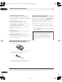
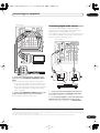
Connecting your TV and DVD player
VIDEO
IN
3 Connect a coaxial-type1 digital audio output on
your DVD player to the COAXIAL 1 (DVD/LD) input.
Use a coaxial cable designed for digital audio.
S-VIDEO
IN
4 Connect the stereo audio outputs on your DVD
player to the DVD/LD AUDIO inputs.
Connect using a stereo RCA/phono jack cable.
1
TV
VSX-1016TXV
ANTENNA
OPTICAL
DIGITAL
IN 1
OUT
AM LOOP
COMPONENT VIDEO
PB
Y
PR
IN 1
IN 2
(DVR/
VCR1)
Y
2 Connect a composite or S-video output on your DVD
player to the DVD/LD VIDEO or DVD/LD S-VIDEO input.
Connect using a standard video cable or an S-video
cable.
PB
PR
IN
1
PRE OUT
L
CENTER
R
SUB
FRONT WOOFER
L
OUT
• If your DVD player has multichannel analog outputs,
you can connect these instead. See also Connecting
the multichannel analog inputs on page 42.
IN 2
(TV/SAT)
OUT
IN
2
IN
3
Y
IN 3
PB
PR
Y
ASSIGNABLE 1
(CD)
PB
PR
3
R SURROUND
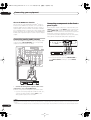
Connecting a satellite/cable receiver
or other set-top box
ASSIGNABLE
1
HDMI
S-VIDEO
3
CONTROL
IN
IN
OUT
IN
OUT
IN
MONITOR
OUT
IN
IN
OUT
IN
OUT
IN
L
DVD/LD
TV/SAT
OUT
XM
VIDEO
IN
IN
AUDIO
IN
OUT
IN
CD
CD-R/TAPE/MD
CENTER
L
Satellite and cable receivers, and terrestrial digital TV
tuners are all examples of so-called ‘set-top boxes’.
IN 1
(DVD/LD)
R
IN 2
(DVR/VCR2)
DVR/VCR1
DVR/VCR2
R
SUB
WOOFER
COAXIAL
FRONT
ASSIGNABLE
1 2
MULTI CH IN
ANTENNA
OPTICAL
IN 1
DIGITAL
OUT
AM LOOP
COMPONENT VIDEO
PB
Y
PR
IN 1
IN 2
(DVR/
VCR1)
Y
PB
PR
IN
1
P
L
CENTER
L
R
SUB
FRONT WOOFER
R
OUT
IN 2
(TV/SAT)
OUT
IN
2
Y
IN 3
IN
3
PB
PR
Y
ASSIGNABLE 1
(CD)
PB
PR
3
ASSIGNABLE
1
HDMI
S-VIDEO
3
CONTROL
IN
IN
OUT
IN
OUT
IN
MONITOR
OUT
IN
IN
OUT
IN
OUT
IN
L
DVD/LD
TV/SAT
OUT
XM
R
AUDIO L
ANALOG OUT
S-VIDEO
VIDEO OUT
VIDEO
IN
IN
OPTICAL
COAXIAL
DIGITAL OUT
AUDIO
IN
OUT
IN
CD
CD-R/TAPE/MD
L
IN 1
(DVD/LD)
R
3
4
2
IN 2
(DVR/VCR2)
DVR/VCR1
DVR/VCR2
R
COAXIAL
FRONT
ASSIGNABLE
1 2
MULTI C
VSX-1016TXV
DVD player
The diagram shows a basic setup of this receiver together
with a TV and DVD player, with S-video or composite
video connections. Different TVs and DVD players may
offer alternative connections. See also Using the
component video jacks on page 14 if your TV and/or DVD
player has component video inputs/outputs. If your DVD
player offers multichannel analog audio outputs, see
Connecting the multichannel analog inputs on page 42.
1 Connect the MONITOR OUT video jack to a video
input on your TV.
Use a standard RCA/phono jack video cable to connect to
the composite video jack, or for higher quality video, use
an S-video cable to connect to the S-video jack.
DIGITAL OUT
R
AUDIO L
VIDEO
S-VIDEO
AV OUT
STB
1 Connect the audio/video outputs on the set-top box
to the TV/SAT AUDIO and VIDEO inputs.
Connect using a stereo RCA/phono jack cable and a
video or S-video cable.
Note
1 If your DVD player only has an optical digital output, you can connect it to one of the optical inputs on this receiver using an optical cable. When you set
up the receiver you’ll need to tell the receiver which input you connected the player to (see The Input Assign menu on page 46).
13
En
VSX-1016TXV_KU.book.fm 14 ページ 2006年3月24日 金曜日 午後9時19分
03
Connecting your equipment
2 Connect an optical-type1 digital audio output from
your set-top box to the OPTICAL 2 (TV/SAT) input.2
Use an optical cable for the connection.
Connecting a DVD/HDD recorder, VCR
and other video sources
This receiver has two sets of audio/video inputs and
outputs suitable for connecting analog or digital video
devices, including DVD/HDD recorders and VCRs.
VSX-1016TXV
• For a second recorder, use the DVR/VCR2 outputs.
3 If the device can output digital audio, connect an
optical-type3 digital audio output from the recorder to
the OPTICAL 1 (DVR/VCR1) input.
Use an optical cable for the connection.4
• For a second recorder, use the COAXIAL 2 (DVR/
VCR2) inputs.
ANTENNA
OPTICAL
IN 1
2 If the device can record, connect the DVR/VCR1
AUDIO and VIDEO outputs to the recorder’s audio/
video inputs.
Use a stereo RCA/phono jack audio cable for the audio
connection and a video or S-video cable for the video
connection.
DIGITAL
OUT
AM LOOP
COMPONENT VIDEO
PB
Y
PR
IN 1
IN 2
(DVR/
VCR1)
Y
PB
PR
IN
1
PRE OUT
L
CENTER
R
SUB
FRONT WOOFER
L
L
OUT
Using the component video jacks
IN 2
(TV/SAT)
OUT
IN
2
IN
3
PB
Y
IN 3
PR
Y
ASSIGNABLE 1
(CD)
PB
PR
3
R SURROUND
ASSIGNABLE
1
HDMI
S-VIDEO
3
CONTROL
IN
IN
OUT
IN
OUT
IN
MONITOR
OUT
IN
IN
OUT
IN
OUT
IN
L
DVD/LD
TV/SAT
OUT
XM
VIDEO
IN
IN
AUDIO
IN
OUT
IN
CD
CD-R/TAPE/MD
CENTER
L
IN 1
(DVD/LD)
R
IN 2
(DVR/VCR2)
OPTICAL
DVR/VCR1
R
DVR/VCR2
SUB
WOOFER
COAXIAL
FRONT
ASSIGNABLE
1 2
MULTI CH IN
COAXIAL
R
AUDIO
L
DIGITAL OUT
VIDEO
AV IN
3
S-VIDEO
R
AUDIO
L
VIDEO
Component video should give superior picture quality
when compared to composite or S-video. You can also
take advantage of progressive scan video (if your source
and TV are both compatible), which delivers a very stable,
flicker-free picture. See the manuals that came with your
TV and source component to check whether they are
compatible with progressive-scan video.
S-VIDEO
AV OUT
1
2
DVR, VCR, etc.
1 Connect the audio/video outputs of the video
player/recorder to the DVR/VCR1 AUDIO and VIDEO
inputs.
Use a stereo RCA/phono jack audio cable for the audio
connection and a video or S-video cable for the video
connection.
• For a second recorder, use the DVR/VCR2 IN inputs.
Note
1 If your set-top box only has a coaxial digital output, you can connect it to one of the coaxial inputs on this receiver using a coaxial digital audio cable.
When you set up the receiver you’ll need to tell the receiver which input you connected the set-top box to (see The Input Assign menu on page 46).
2 If your satellite/cable receiver doesn’t have a digital audio output, you can skip this step.
3 • In order to record, you must connect the analog audio cables (the digital connection is for playback only).
• If your video component doesn’t have a digital audio output, you can skip this step.
4 If your recorder only has a coaxial digital output, you can connect it to one of the coaxial inputs on this receiver using a coaxial digital audio cable. When
you set up the receiver you’ll need to tell the receiver which input you connected the recorder to (see also The Input Assign menu on page 46).
14
En
VSX-1016TXV_KU.book.fm 15 ページ 2006年3月24日 金曜日 午後9時19分
Connecting your equipment
03
VSX-1016TXV
Connecting digital audio sources
ANTENNA
OPTICAL
DIGITAL
IN 1
OUT
AM LOOP
COMPONENT VIDEO
PB
Y
PR
IN 1
IN 2
(DVR/
VCR1)
Y
PB
PR
IN
1
L
CENTER
R
SUB
FRONT WOOFER
OUT
IN 2
(TV/SAT)
OUT
IN
3
IN
2
Y
IN 3
PB
PR
Y
ASSIGNABLE 1
(CD)
PB
PR
3
ASSIGNABLE
1
HDMI
S-VIDEO
3
CONTROL
IN
IN
OUT
IN
OUT
IN
MONITO
OUT
IN
IN
OUT
IN
OUT
IN
L
This receiver has both digital inputs and outputs,
allowing you to connect digital audio components for
playback and for making digital recordings.
Most digital components also have analog connections.
See Connecting analog audio sources on the following
page if you want to connect these too.
OUT
XM
IN
IN
VSX-1016TXV
VIDEO
AUDIO
IN
OUT
IN
ANTENNA
OPTICAL
L
IN 1
IN 1
DIGITAL
(DVD/LD)
OUT
R
AM
IN 2
(DVR/VCR2)
CD
CD-R/TAPE/MD
DVD/LD
TV/SAT
DVR/VCR1
DVR/VCR2
FRONT
ASSIGNABLE
1 2
MULTI C
COMPONENT VIDEO
PB
Y
PR
IN 1
R
COAXIAL
IN 2
(DVR/
VCR1)
Y
PB
PR
IN
1
OUT
IN 2
(TV/SAT)
OUT
IN
2
Y
IN 3
IN
3
PB
PR
Y
ASSIGNABLE 1
(CD)
PB
PR
R
3
ASSIGNABLE
1
HDMI
S-VIDEO
3
CONTROL
IN
IN
OUT
IN
OUT
IN
IN
OUT
IN
OUT
DVD/LD
TV/SAT
OUT
XM
VIDEO
IN
IN
Y
AUDIO
IN
OUT
IN
CD
CD-R/TAPE/MD
L
IN 1
PB
(DVD/LD)
PR
(DVR/VCR2)
R
IN 2
DVR/VCR1
DVR
COAXIAL
2
COMPONENT
VIDEO
ASSIGNABLE
1 2
TV
Y
PB
PR
1
COMPONENT
VIDEO
DVD player
1 Connect the component video outputs of your
source to a set of ASSIGNABLE COMPONENT VIDEO
inputs.
Connect using a three-way component video cable.
• Since they are assignable, it doesn’t matter which
component video inputs you use for which source.
After connecting everything, you’ll need to assign the
component video inputs—see The Input Assign
menu on page 46.
2 Connect the COMPONENT VIDEO OUT jacks to the
component video inputs on your TV or monitor.
Use a three-way component video cable.
1
OPTICAL
COAXIAL
DIGITAL OUT
OPTICAL
2
DIGITAL IN
CD-R, MD, DAT, etc.
1 Connect an optical-type1 digital audio output on
your digital component to the DIGITAL 3 (CD) input.
Use an optical cable for the connection.
2 For recording equipment, connect the optical-type
DIGITAL output to a digital input on the recorder.
Use an optical cable to connect to the DIGITAL OUT.2
Note
1 • If your digital component only has a coaxial digital output, you can connect it to one of the coaxial inputs on this receiver using a coaxial cable. When
you set up the receiver you’ll need to tell the receiver which input you connected the component to (see also The Input Assign menu on page 46).
• The digital outputs from other components can be connected to any spare digital audio inputs on this receiver. You can assign them when setting up
the receiver (see also The Input Assign menu on page 46).
2 In order to record some digital sources, you must make analog connections as explained in Connecting analog audio sources below.
15
En
VSX-1016TXV_KU.book.fm 16 ページ 2006年3月24日 金曜日 午後9時19分
03
Connecting your equipment
About the WMA9 Pro decoder
This unit has an on-board Windows Media® Audio 9
Professional1 (WMA9 Pro) decoder, so it is possible to
playback WMA9 Pro-encoded audio using a coaxial or
optical digital connection when connected to a WMA9
Pro-compatible player. However, the connected PC, DVD
player, set-top box, etc. must be able to output WMA9 Pro
format audio signals through a coaxial or optical digital
output.
Connecting a component to the front
panel inputs
The front panel inputs comprise a composite video jack
(VIDEO), an S-Video jack (S-VIDEO), stereo analog audio
inputs (AUDIO L/R) and an optical digital audio input
(DIGITAL). You can use these connections for any kind of
audio/video component, but they are especially
convenient for portable equipment such as camcorders,
video games and portable audio/video equipment.
Connecting analog audio sources
S - VIDEO
This receiver features two stereo audio-only inputs. One
of these inputs (CD-R/TAPE/MD) has corresponding
outputs for use with audio recorders.
SYSTEM
SETUP
RETURN
TONE
TUNING/
STATION
TUNER
EDIT
VIDEO/GAME INPUT
L AUDIO R
DIGITAL IN
MCACC
SETUP MIC
SPEAKERS
MULTI JOG
ANTENNA
OPTICAL
IN 1
VIDEO
PHONES
DIGITAL
OUT
AM LOOP
COMPONENT VIDEO
PB
Y
PR
IN 1
IN 2
(DVR/
VCR1)
PB
Y
PR
IN
1
PRE OUT
L
CENTER
R
SUB
FRONT WOOFER
L
OUT
IN 2
(TV/SAT)
OUT
IN
2
Y
IN 3
IN
3
PB
PR
PB
Y
ASSIGNABLE 1
(CD)
PR
3
R SURROUND
ASSIGNABLE
1
HDMI
3
IN
IN
OUT
IN
OUT
IN
MONITOR
OUT
IN
IN
OUT
IN
OUT
IN
L
DVD/LD
TV/SAT
CONTROL
OUT
XM
VIDEO
IN
IN
AUDIO
IN
OUT
CD
CD-R/TAPE/MD
VIDEO/AUDIO OUTPUT
DIGITAL OUT
TV game, video camera, etc.
S-VIDEO
IN
CENTER
L
IN 1
(DVD/LD)
• Select these inputs by pressing VIDEO/GAME or
using INPUT SELECT (remote) to select VIDEO/
GAME.
R
IN 2
(DVR/VCR2)
DVR/VCR1
DVR/VCR2
R
SUB
WOOFER
COAXIAL
FRONT
ASSIGNABLE
1 2
MULTI CH IN
VSX-1016TXV
OUT
PLAY
IN
REC
R
L
AUDIO IN/OUT
Tape deck, etc.
• Connect the analog audio outputs of the source
component to one of the AUDIO inputs.
Connect using a stereo RCA/phono jack audio cable.
• If you’re connecting a tape deck, MD recorder, etc.,
connect the analog audio outputs (OUT) to the
analog audio inputs on the recorder.
Note
1 • Microsoft, Windows Media®, and the Windows logo are trademarks, or registered trademarks of Microsoft Corporation in the United States and/or other
countries.
• With WMA9 Pro, sound problems may occur depending on your computer system. Note that WMA9 Pro 96 kHz sources will be downsampled to 48 kHz.
16
En
VSX-1016TXV_KU.book.fm 17 ページ 2006年3月24日 金曜日 午後9時19分
Connecting your equipment
03
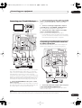
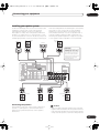
Installing your speaker system
main surround speakers should always be connected as
a pair, but you can connect just one surround back
speaker if you like (it must be connected to the left
surround back terminal). You can use speakers with a
nominal impedance between 6 Ω to 16 Ω (please see
Switching the speaker impedance on page 50 if you plan
to use speakers with an impedance of less than 8 Ω).
To take full advantage of the receiver’s surround sound
capabilities connect front, center, surround and
surround back speakers, as well as a subwoofer.
Although this is ideal, other configurations with fewer
speakers—no subwoofer or no center speaker, or even
no surround speakers—will work. At the very least, front
left and right speakers only are necessary. Note that your
Front
right
Front
left
Subwoofer
Center
CAUTION
LINE LEVEL
INPUT
These speaker terminals carry
HAZARDOUS LIVE voltage.
To prevent the risk of electric
shock when connecting or
disconnecting the speaker
cables, disconnect the power
cord before touching any
uninsulated parts.
ANTENNA
OPTICAL
IN 1
DIGITAL
OUT
AM LOOP
COMPONENT VIDEO
PB
Y
PR
IN 1
IN 2
(DVR/
VCR1)
Y
PB
PR
IN
1
AC OUTLET
PRE OUT
L
CENTER
R
SUB
FRONT WOOFER
L (Single)
L
OUT
IN 2
(TV/SAT)
OUT
IN
2
Y
IN 3
IN
3
PB
PR
Y
ASSIGNABLE 1
(CD)
PB
PR
3
R
R SUR-
SURROUND
ROUND BACK
SWITCHED 100 W(0.8 A) MAX
ASSIGNABLE
1
HDMI
S-VIDEO
3
IN
CONTROL
IN
OUT
IN
OUT
IN
SPEAKERS
MONITOR
OUT
A
OUT
R
FRONT
L
CENTER
R
SURROUND
XM
L
SURROUND BACK /
R
B
L (Single)
VIDEO
IN
IN
AUDIO
IN
OUT
IN
CD
CD-R/TAPE/MD
IN
IN
DVD/LD
TV/SAT
OUT
IN
OUT
IN
L
CENTER
L
SUB
WOOFER
SURROUND
L
L
IN 1
(DVD/LD)
R
IN 2
(DVR/VCR2)
DVR/VCR1
DVR/VCR2
R
COAXIAL
FRONT
ASSIGNABLE
1 2
MULTI CH IN
R
SEE INSTRUCTION MANUAL
R
SELECTABLE
SURROUND
BACK
VSX-1016TXV
Surround
left
Surround
right
Surround
back left
Connecting the speakers
Each speaker connection on the receiver comprises a
positive (+) and negative (–) terminal. Make sure to
match these up with the terminals on the speakers
themselves.
Surround
back right
Caution
• Make sure that all the bare speaker wire is twisted
together and inserted fully into the speaker terminal.
If any of the bare speaker wire touches the back panel
it may cause the power to cut off as a safety measure.
17
En
VSX-1016TXV_KU.book.fm 18 ページ 2006年3月24日 金曜日 午後9時19分
03
Connecting your equipment
Bare wire connections
Make sure that the speaker cable you’re going to use is
properly prepared with about 3/8 in. of insulator stripped
from each wire, and the exposed wire strands twisted
together (fig. A).
To connect a terminal, unscrew the terminal a few turns
until there is enough space to insert the exposed wire
(fig. B). Once the wire is in position, tighten the terminal
until the wire is firmly clamped (fig. C).
fig. A
fig. B
fig. C
3
/8 in.
Banana plug connections
If you want to use speaker cables terminated with banana
plugs, screw the speaker terminal fully shut then plug the
banana plug into the end of the speaker terminal.
• When placing speakers near the TV, we recommend
using magnetically shielded speakers to prevent
possible interference, such as discoloration of the
picture when the TV is switched on. If you do not have
magnetically shielded speakers and notice
discoloration of the TV picture, move the speakers
farther away from the TV.
• If you're using a center speaker, place the front
speakers at a wider angle. If not, place them at a
narrower angle.
• Place the center speaker above or below the TV so
that the sound of the center channel is localized at
the TV screen. Also, make sure the center speaker
does not cross the line formed by the leading edge of
the front left and right speakers.
• It is best to angle the speakers towards the listening
position. The angle depends on the size of the room.
Use less of an angle for bigger rooms.
• Surround and surround back speakers should be
positioned a foot-and-a-half to three feet higher than
your ears and titled slight downward. Make sure the
speakers don't face each other. For DVD-Audio, the
speakers should be more directly behind the listener
than for home theater playback.
• Try not to place the surround speakers farther away
from the listening position than the front and center
speakers. Doing so can weaken the surround sound
effect.
Important
• Please refer to the manual that came with your
speakers for details on how to connect the other end
of the speaker cables to your speakers.
• Other connections on page 40 provides greater detail
on alternate speaker setups, such as using speaker
system B (page 42), bi-amping (page 43) and biwiring (page 44).
• If you are using a THX certified subwoofer use the
THX INPUT jack on the subwoofer (if your subwoofer
has one) or switch the filter position to THX on your
subwoofer.
• To achieve the best possible surround sound, install
your speakers as shown below. Be sure all speakers
are installed securely to prevent accidents and
improve sound quality.
Front
left
Front
right
Center
Subwoofer
Surround
left
Surround
right
Placing the speakers
Where you put your speakers in the room has a big effect
on the quality of the sound. The following guidelines
should help you to get the best sound from your system.
• The subwoofer can be placed on the floor. Ideally, the
other speakers should be at about ear-level when
you’re listening to them. Putting the speakers on the
floor (except the subwoofer), or mounting them very
high on a wall is not recommended.
• For the best stereo effect, place the front speakers
6 ft. to 9 ft. apart, at equal distance from the TV.
18
En
Listening position
Surround back left
Surround back right
Single surround back speaker
Caution
• Make sure that all speakers are securely installed.
This not only improves sound quality, but also
reduces the risk of damage or injury resulting from
speakers being knocked over or falling in the event of
external shocks such as earthquakes.
03_connecting_up.fm 19 ページ 2006年4月4日 火曜日 午後6時13分
Connecting your equipment
03
The diagrams below show suggested surround and
surround back speaker orientation. The first diagram (fig.
A) shows orientation with one surround back speaker (or
none) connected. The second (fig. B) shows orientation
with two surround back speakers connected.
90º to 120º
Connecting antennas
Connect the AM loop antenna and the FM wire antenna
as shown below. To improve reception and sound quality,
connect external antennas (see Connecting external
antennas below).
fig. a
fig. b
fig. c
SR
SL
SR
SL
0º to 60º
SR
SL
3
SBL
SB
fig. A
SBL
SBR
SBR
ANTENNA
fig. B
5
FM UNBAL 75 Ω
• If you have two surround back speakers THX
recommends placing them together and the same
distance from your listening position (see below).
AM LOOP
1
4
2
THX speaker system setup
If you have a complete THX speaker system, follow the
diagram below to place your speakers. Note that the
surround speakers ( indicates bi-polar radiating
speakers) should output at an angle parallel to the
listener.
L
C
R
1 Pull off the protective shields of both AM antenna
wires.
2 Push open the tabs, then insert one wire fully into
each terminal, then release the tabs to secure the AM
antenna wires.
3 Fix the AM loop antenna to the attached stand.
To fix the stand to the antenna, bend in the direction
indicated by the arrow (fig. a) then clip the loop onto the
stand (fig. b).
SL
SR
Surround
Surround
SBL
SBR
Surround back
• If you have two surround back speakers THX
recommends placing them together and the same
distance from your listening position for the following
THX modes: THX Select2 CINEMA, THX
MUSICMODE and THX GAMES MODE.
• If you plan to mount the AM antenna to a wall or other
surface, secure the stand with screws (fig. c) before
clipping the loop to the stand. Make sure the
reception is clear.
4 Place the AM antenna on a flat surface and in a
direction giving the best reception.
5 Connect the FM wire antenna in the same way as
the AM loop antenna.
For best results, extend the FM antenna fully and fix to a
wall or door frame. Don’t drape loosely or leave coiled up.
19
En
VSX-1016TXV_KU.book.fm 20 ページ 2006年3月24日 金曜日 午後9時19分
03
Connecting your equipment
Connecting external antennas
To improve FM reception connect an external FM
antenna to the FM UNBAL 75 Ω terminal.
Plugging in the receiver
Only plug in after you have connected all your
components to this receiver, including the speakers.
Caution
• Handle the power cord by the plug part. Do not pull
out the plug by tugging the cord, and never touch the
power cord when your hands are wet, as this could
cause a short circuit or electric shock. Do not place
the unit, a piece of furniture, or other object on the
power cord or pinch the cord in any other way. Never
make a knot in the cord or tie it with other cables. The
power cords should be routed so that they are not
likely to be stepped on. A damaged power cord can
cause a fire or give you an electric shock. Check the
power cord once in a while. If you find it damaged,
ask your nearest Pioneer authorized independent
service company for a replacement.
75 Ω coaxial cable
ANTENNA
FM UNBAL 75 Ω
AM LOOP
To improve AM reception, connect a 15 ft. to 18 ft. length
of vinyl-coated wire to the AM LOOP terminals without
disconnecting the supplied AM loop antenna.
• The receiver should be disconnected by removing the
mains plug from the wall socket when not in regular
use, e.g., when on vacation.
For the best possible reception, suspend horizontally
outdoors.
• Make sure the blue STANDBY/ON light has gone
out before unplugging.
Outdoor antenna
Indoor antenna
(vinyl-coated wire)
ANTENNA
FM UNBAL 75 Ω
15 ft. to 18 ft.
AM LOOP
•
Plug the power cord into a power outlet.
AC outlet
Power supplied through this outlet is turned on and off by
the receiver's power switch. Total electrical power
consumption of connected equipment should not exceed
100 W (0.8 A).
Caution
• Do not connect a TV set, monitor, heater, or similar
appliance to this unit's AC outlet.
• Do not connect appliances with high power
consumption to the AC outlet in order to avoid
overheating and fire risk. This can also cause the
receiver to malfunction.
• Since a subwoofer or power amplifier can exceed the
100 W maximum when playing sources at a high
volume, this type of equipment should not be
connected to the AC outlet.
20
En
VSX-1016TXV_KU.book.fm 21 ページ 2006年3月24日 金曜日 午後9時19分
Controls and displays
04
Chapter 4:
Controls and displays
Front panel
1
2
3
4
5
6
7
8
9
AUDIO/VIDEO MULTI-CHANNEL RECEIVER
10
VSX-1016TXV
PHASE
CONTROL
STANDBY/ON
DIGITAL PRECISION PROCESSING
PHASE ACOUSTIC LISTENING
MODE
EQ
CONTROL
DVD/LD
TV/SAT
DVR /VCR1
DVR/VCR2
VIDEO/GAME
CD
CD-R / TAPE / MD
FM/AM
XM
MULTI CH
IN
VIDEO
SELECT
SOUND
SIGNAL
SB ch
SELECT PROCESSING RETRIEVER
MASTER
VOLUME
ENTER
MULTI JOG
S - VIDEO
VIDEO
PHONES
SYSTEM
SETUP
RETURN
TONE
TUNING/
STATION
TUNER
EDIT
VIDEO/GAME INPUT
L AUDIO R
DIGITAL IN
MCACC
SETUP MIC
SPEAKERS
MULTI JOG
11
12
13
16
17
18
19
20
21
SYSTEM
SETUP
RETURN
TONE
TUNING/
STATION
TUNER
EDIT
SPEAKERS
14
15
MULTI JOG
1 MULTI JOG dial
Use the MULTI JOG dial to select various settings and
menu options.
7 Remote sensor
Receives the signals from the remote control (see
Operating range of remote control unit on page 22).
2 STANDBY/ON
Switches the receiver between on and standby. Power
indicator lights when the receiver is on.
8 MCACC indicator
Lights when Acoustic Calibration EQ (page 35) is on
(Acoustic Calibration EQ is automatically set to ALL CH
ADJUST after the Auto MCACC Setup (page 8) or EQ
Auto Setup (page 35)).
3
PHASE CONTROL – Press to switch on/off Basic
Phase Control (page 10).
ACOUSTIC EQ – Press to select an Acoustic
Calibration EQ setting (page 28).
LISTENING MODE – Use with the MULTI JOG dial to
select the various listening modes (page 26).
4 PHASE CONTROL indicator
Lights when Basic Phase Control is switched on
(page 10).
5 DIGITAL PRECISION PROCESSING indicator
Lights to indicate digital processing (for example, it
disappears when listening through the multichannel
analog inputs).
6 Character display
See Display on page 23.
9
SIGNAL SELECT – Use to select an input signal
(page 29).
SBch PROCESSING – Selects the surround back
channel mode (page 29) or virtual surround back
mode (page 29).
SOUND RETRIEVER – Press to restore CD quality
sound to compressed audio sources (page 30).
10 MASTER VOLUME dial
11 ENTER
12 PHONES jack
Use to connect headphones. When the headphones are
connected, there is no sound output from the speakers.
21
En
VSX-1016TXV_KU.book.fm 22 ページ 2006年3月24日 金曜日 午後9時19分
04
Controls and displays
13 Input source buttons
Press to select an input source (press VIDEO SELECT
repeatedly to select the video source (page 49)).
14 VIDEO/GAME INPUT
See Connecting a component to the front panel inputs on
page 16.
15 MCACC SETUP MIC jack
Use to connect the supplied microphone.
16 SYSTEM SETUP
Press to access the System Setup menu (see page 33).
17 RETURN
Press to confirm and exit the current menu screen.
18 TONE
Press this button to access the bass and treble controls,
which you can then adjust with the MULTI JOG dial
(page 30).
19 TUNING/STATION
Use to find radio frequencies and to select preset
stations (page 31).
20 TUNER EDIT
Use with the MULTI JOG dial to memorize and name
stations for recall (page 31).
21 SPEAKERS
Use to change the speaker system (page 43).
Operating range of remote control unit
The remote control may not work properly if:
• There are obstacles between the remote control and
the receiver's remote sensor.
• Direct sunlight or fluorescent light is shining onto the
remote sensor.
• The receiver is located near a device that is emitting
infrared rays.
• The receiver is operated simultaneously with another
infrared remote control unit.
30
30
DOWN
DOWN
23 ft. (7 m)
22
En
VSX-1016TXV_KU.book.fm 23 ページ 2006年3月24日 金曜日 午後9時19分
Controls and displays
04
Display
1
2
3
4
5
6
7
8
9
SIGNAL
MIDNIGHT TUNED
L
C
R 2DIGITAL DTS VIDEO CONV. V.SB
DIALOGUE LOUDNESS STEREO
WMA9 Pro 96/24
SL
S SR
OVER ATT
TONE MONO
SBL SB SBR
DIGITAL
LFE
ANALOG
AUTO
dB
SR+
Neo : 6
2PRO LOGIC
THX ADV.SURROUND
STEREO STANDARD
SLEEP
SP AB
10
11
12
13
1 SIGNAL indicators
Light to indicate the currently selected input signal.
AUTO lights when the receiver is set to select the input
signal automatically (page 29).
2 Program format indicators
These change according to which channels are active in
digital sources.
14
9
15
Master volume level
10 Speaker indicators
Indicate the current speaker system, A and/or B (page 43).
11 Listening mode indicators
THX – Lights when a Home THX mode is selected.
ADV. SURROUND – Lights when an Advanced
Surround mode has been selected.
L – Left front channel
C – Center channel
R – Right front channel
SL – Left surround channel
S – Surround channel (mono)
SR – Right surround channel
SBL – Left surround back channel
SB – Surround back channel (mono)
SBR – Right surround back channel
LFE – Low frequency effects channel
12 SLEEP
Lights when the receiver is in sleep mode (page 50).
3 Digital format indicators
Light when a signal encoded in the corresponding format
is detected.
13 Matrix decoding format indicators
2PRO LOGIC IIx – This lights to indicate 2Pro
Logic II / 2Pro Logic IIx decoding (page 26).
4 OVER / ATT
OVER lights to indicate that the level of an analog source
is too high. ATT lights when you use the attenuator
(ANALOG ATT) to reduce it.
5 VIDEO CONV.
Lights when digital video conversion is enabled (page 48).
6 V.SB
Lights during Virtual surround back processing (page 29).
STEREO – Lights when stereo listening is switched
on (see Listening in stereo on page 28).
STANDARD – Lights when a Standard Surround
mode is switched on (see Listening in surround
sound on page 26).
Neo:6 – When one of the Neo:6 modes of the receiver
is on, this lights to indicate Neo:6 processing
(page 26).
14 Character display
Displays various system information.
15 SR+
Lights when the SR+ mode is switched on (page 45).
7 Sound processing indicators
Light according to the active sound processing feature.
8
TUNER indicators
TUNED – Lights when a broadcast is being received.
STEREO – Lights when a stereo FM broadcast is
being received in auto stereo mode.
MONO – Lights when the mono mode is set using
the MPX button.
23
En
VSX-1016TXV_KU.book.fm 24 ページ 2006年3月24日 金曜日 午後9時19分
04
Controls and displays
4 Number buttons and other receiver/component
controls
Use the number buttons to directly select a radio
frequency (page 31) or the tracks on a CD, DVD, etc.
Remote control
RECEIVER
SYSTEM OFF
INPUT
SELECT
1
2
SOURCE
12
Press RECEIVER first to access:
13
DVD
TV
DVR1
CD
CD-R
3
TV CTRL
XM RADIO
4
D.ACCESS
TUNER
RECEIVER
14
ANALOG
ATT
SLEEP
SB ch
SR+
DIMMER
MIDNIGHT/
LOUDNESS
DIALOG E
PHASE
S.RETRIEVER
CLASS
+10
DIMMER – Dims or brightens the display (page 50).
MIDNIGHT/LOUDNESS – Use Midnight when
listening to movie soundtracks at low volume. Use
Loudness to boost the bass and treble at low volume
(page 30).
DISC
MENU
TOP MENU
TUNE
DTV MENU
ST
ST
ENTER
SETUP
GUIDE
CATEGORY
TUNE
T.EDIT
DIALOG E – Use to make dialog stand out when
watching TV or a movie (page 30).
RETURN
BAND
TV CONTROL
TV VOL
DTV ON/OFF
INPUT
SELECT
REC
TV CH
VOL
DTV INFO
MUTE
8
AUDIO SUBTITLE
DISP
9
10
11
THX
15
16
HDD
DVD
CH
CH
STANDARD ADV.SURR
STEREO
CLASS – Switches between the three banks (classes)
of radio station presets (page 31).
17
RECEIVER
The remote has been conveniently color-coded according
to component control using the following system (press
the corresponding input source button to access):
• Green – Receiver controls (see below)
• Red – DVD controls (page 55)
• Blue – Tuner/XM Radio controls (page 31)
• White – Other controls (page 55)
1 RECEIVER
This switches between standby and on for this receiver.
2 INPUT SELECT
Use to select the input source (use SHIFT for INPUT
SELECT
).
3 Input source buttons
Press to select control of other components (see
Controlling the rest of your system on page 51).
24
En
S. RETRIEVER – Press to restore CD quality sound to
compressed audio sources (page 30).
D.ACCESS – After pressing, you can access a radio
station directly using the number buttons (page 31).
MULTI OPE AUTO SURR ACOUSTIC EQ SIGNAL SEL
SHIFT EFFECT/CH SEL
PHASE – Press to switch on/off Basic Phase Control
(page 10).
Press TUNER first to access:
REC STOP JUKEBOX
MPX
ANALOG ATT – Attenuates (lowers) the level of an
analog input signal to prevent distortion (page 49).
SR+ – Switches the SR+ mode on/off (page 45).
ENTER
7
SLEEP – Use to put the receiver in sleep mode and
select the amount of time before sleep (page 50).
SBch – Use to select the surround/virtual back
channel mode (page 29).
DVR 2
5
6
DISC (ENTER) can be used to enter commands for TV or
DTV, and also to select a disc in a multi-CD player.
5 Tuner/component control buttons/SETUP
These button controls can be accessed after you have
selected the corresponding input source button (DVD,
DVR1, TV, etc.). The BAND and T.EDIT tuner controls are
explained from page 31. Press RECEIVER first to access
the following controls:
SETUP – Use to access the System Setup menu
(page 33).
RETURN – Press to confirm and exit the current
menu screen (also use to return to the previous menu
with DVDs or to select closed captioning with DTV).
6 (TUNE/ST) /ENTER
Use the arrow buttons when setting up your surround
sound system (page 33). Also used to control DVD
menus/options and for deck 1 of a double cassette deck
player. Use the TUNE / buttons to find radio
frequencies and use ST / to find preset stations
(page 31).
04_controls_displays.fm 25 ページ 2006年4月4日 火曜日 午後6時15分
Controls and displays
7 TV CONTROL buttons
These buttons are dedicated to control the TV assigned to
the TV CTRL button. Thus if you only have one TV to hook
up to this system assign it to the TV CTRL input source
button. If you have two TVs, assign the main TV to the TV
CTRL button (see page 51 for more on this).
TV – Use to turn on/off the power of the TV.
TV VOL +/– – Use to adjust the volume on your TV.
INPUT SELECT – Use to select the TV input signal.
TV CH +/– – Use to select channels.
8 Component control buttons
The main buttons (, , etc.) are used to control a
component after you have selected it using the input
source buttons.
The controls above these buttons can be accessed after
you have selected the corresponding input source button
(for example DVD, DVR1 or TV). The following controls
can be accessed when listening to the built-in tuner:
MPX – Switches between stereo and mono reception
of FM broadcasts. If the signal is weak then switching
to mono will improve the sound quality (page 31).
DISP – Switches between named station presets and
radio frequencies (page 32).
9
Receiver controls
THX – Press to select a Home THX listening mode
(page 27).
STANDARD – Press for Standard decoding and to
switch between the various 2Pro Logic IIx and
Neo:6 options (page 26).
ADV.SURR – Use to switch between the various
surround modes (page 27).
STEREO – Switches between direct and stereo
playback. Direct playback bypasses the tone controls
and any other signal processing for the most
accurate reproduction of a source (page 28).
AUTO SURR – Selects Auto Surround (Auto playback
on page 26).
ACOUSTIC EQ – Press to select an Acoustic
Calibration EQ setting (page 28).
04
13 Character display (LCD)
This display shows information when transmitting
control signals.
The following commands are shown when you’re setting
the remote to control other components (see Controlling
the rest of your system on page 51):
SETUP – Indicates the setup mode, from which you
choose the options below.
PRESET – See Selecting preset codes directly on
page 51.
LEARNING – See Programming signals from other
remote controls on page 51.
MULTI OP – See Multi Operation and System Off on
page 53.
SYS OFF – See Multi Operation and System Off on
page 53.
DIRECT F – See Direct function on page 53.
ERASE – See Erasing one of the remote control button
settings on page 52.
RESET – See Resetting the remote control presets on
page 52.
READ ID – See Confirming preset codes on page 52.
14 RECEIVER
Switches the remote to control the receiver (used to
select the green commands above the number buttons
(ANALOG ATT, etc)). Also use this button to set up
surround sound (page 8, page 33).
15 VOL +/–
Use to set the listening volume.
16 MUTE
Mutes the sound or restores the sound if it has been
muted (adjusting the volume also restores the sound).
17 EFFECT/CH SEL
Press repeatedly to select a channel, then use +/– to
adjust the level (see Tip on page 38). Also adjusts the
level of the Advanced Surround effects, Dolby Pro
Logic IIx Music, and Neo:6 Music parameters
(page 27). You can then use the +/– buttons to make
these adjustments.
SIGNAL SEL – Use to select an input signal (page 29).
10 MULTI OPE
Use this button to perform multi operations (page 53).
11 SHIFT
Press to access the controls outlined in white boxes (for
example, INPUT SELECT
), or to display the currently
selected input source in the remote control LCD.
12 SOURCE
Press to turn on/off other components connected to the
receiver (see page 51 for more on this).
25
En
VSX-1016TXV_KU.book.fm 26 ページ 2006年3月24日 金曜日 午後9時19分
05
Listening to your system
Chapter 5:
Listening to your system
Important
• The listening modes and many features described in
this section may not be available depending on the
current source (for example, PCM 88.2 kHz / 96 kHz,
DTS 96 kHz (24 bit) or WMA9 Pro), settings and status
of the receiver. See Listening modes with different
input signal formats on page 64 for more on this.
Listening in surround sound
Using this receiver, you can listen to any source in
surround sound. However, the options available will
depend on your speaker setup and the type of source
you’re listening to.
If you connected surround back speakers, see also Using
surround back channel processing on page 29.
Standard surround sound
Tip
• The listening modes described below can also be
selected using the front panel controls. Simply press
LISTENING MODE repeatedly to access the modes
you want, then use the MULTI JOG to select a
particular listening mode (after five seconds the
mode is automatically set).
The following modes provide basic surround sound for
stereo and multichannel sources.2
THX
STANDARD ADV.SURR
STEREO
MULTI OPE AUTO SURR ACOUSTIC EQ SIGNAL SEL
SHIFT EFFECT/CH SEL
RECEIVER
Auto playback
There are many ways to listen back to sources using this
receiver, but for the simplest, most direct listening option
is the Auto Surround feature. The receiver automatically
detects what kind of source you’re playing and selects
multichannel or stereo playback as necessary.1
THX
STANDARD ADV.SURR
STEREO
MULTI OPE AUTO SURR ACOUSTIC EQ SIGNAL SEL
SHIFT EFFECT/CH SEL
RECEIVER
• While listening to a source, press AUTO SURR for
auto playback of a source.
AUTO SURROUND shows briefly in the display before
showing the decoding or playback format. Check the
digital format indicators in the front panel display to see
how the source is being processed.
• When listening to XM Radio, the XM HD Surround
feature is selected automatically (see Using XM HD
Surround on page 41 for more on this).
• While listening to a source, press STANDARD.
If necessary, press repeatedly to select a listening mode.
• If the source is Dolby Digital, DTS, or Dolby Surround
encoded, the proper decoding format will
automatically be selected and shows in the display.3
With two channel sources, you can select from:
• 2 Pro Logic IIx MOVIE – Up to 7.1 channel sound,
especially suited to movie sources
• 2 Pro Logic IIx MUSIC – Up to 7.1 channel sound,
especially suited to music sources4
• 2 Pro Logic IIx GAME– Up to 7.1 channel sound,
especially suited to video games
• 2 PRO LOGIC – 4.1 channel surround sound (sound
from the surround speakers is mono)
• Neo:6 CINEMA – 6.1 channel sound, especially
suited to movie sources
• Neo:6 MUSIC – 6.1 channel sound, especially suited
to music sources5
With multichannel sources, if you have connected
surround back speaker(s) and have selected SBch ON, you
can select (according to format):
Note
1 • Stereo surround (matrix) formats are decoded accordingly using Neo:6 CINEMA or 2 Pro Logic IIx MOVIE (see Listening in surround sound above
for more on these decoding formats).
• The Auto Surround feature is canceled if you connect headphones or select the multichannel analog inputs.
2 In modes that give 6.1 channel sound, the same signal is heard from both surround back speakers.
3 If surround back channel processing (page 29) is switched OFF, or the surround back speakers are set to NO (this happens automatically if the Surround
back speaker setting on page 33 is set to anything but Normal (SB)), 2 Pro Logic IIx becomes 2 Pro Logic II (5.1 channel sound).
4 When listening to 2-channel sources in Dolby Pro Logic IIx Music mode, there are three further parameters you can adjust: Center Width, Dimension,
and Panorama. See Setting the effect options on page 27 to adjust them.
5 When listening to 2-channel sources in Neo:6 Music mode, you can also adjust the center image effect (see Setting the effect options on page 27).
26
En
VSX-1016TXV_KU.book.fm 27 ページ 2006年3月24日 金曜日 午後9時19分
Listening to your system
05
• 2 Pro Logic IIx MOVIE – See above (only available
when you’re using two surround back speakers)
• THX Surround EX – Allows you to hear 6.1 or 7.1
channel playback with 5.1 channel sources
• 2 Pro Logic IIx MUSIC – See above
• THX Select2 CINEMA – Allows you to hear 7.1
channel playback with 5.1 channel sources
• Dolby Digital EX – Creates surround back channel
sound for 5.1 channel sources and provides pure
decoding for 6.1 channel sources (like Dolby Digital
Surround EX)
• DTS-ES – Allows you to hear 6.1 channel playback
with DTS-ES encoded sources
• DTS Neo:6 – Allows you to hear 6.1 channel playback
with DTS encoded sources
Using the Home THX modes
THX and Home THX are technical standards created by
THX Ltd. for cinema and home theater sound. Home THX
is designed to make home theater audio sound more like
what you hear in a cinema.
Different THX options will be available depending on the
source and the setting for surround back channel
processing (see Using surround back channel processing
on page 29 for more on this).
• THX MUSICMODE – Allows you to hear 7.1 channel
playback with 5.1 channel sources
• THX GAMES MODE – Allows you to hear 7.1 channel
playback from the output of a video game console
Using the Advanced surround effects
The Advanced surround effects can be used for a variety
of additional surround sound effects. Most Advanced
Surround modes are designed to be used with film
soundtracks, but some modes are also suited for music
sources. Try different settings with various soundtracks
to see which you like.
THX
STANDARD ADV.SURR
STEREO
MULTI OPE AUTO SURR ACOUSTIC EQ SIGNAL SEL
SHIFT EFFECT/CH SEL
RECEIVER
THX
STANDARD ADV.SURR
STEREO
MULTI OPE AUTO SURR ACOUSTIC EQ SIGNAL SEL
SHIFT EFFECT/CH SEL
RECEIVER
• Press THX (HOME THX) to select a listening mode.1
With two channel sources, press THX repeatedly to select
a matrix-decoding process for the THX CINEMA mode
(see Listening in surround sound above for an
explanation of each process):
• 2 Pro Logic IIx MOVIE+THX
• 2 PRO LOGIC+THX
• Neo:6 CINEMA+THX
• THX GAMES MODE
With multichannel sources, press THX (HOME THX)
repeatedly to select from:2
• THX CINEMA – Gives you cinema-quality sound from
your home theatre system using all the speakers in
your setup
• 2 Pro Logic IIx MOVIE+THX – Especially suited to
movie sources, this allows you to hear 7.1 channel
playback with 5.1 channel sources
• Press ADV.SURR repeatedly to select a listening
mode.3
• ADVANCED MOVIE – Suitable for movie sources.
• ADVANCED MUSIC – Suitable for music sources.
• TV SURROUND – Provides surround sound for both
mono and stereo TV sources.
• SPORTS – Suitable for sports programs.
• ADVANCED GAME – Suitable for video games.
• EXPANDED – Simulates multichannel surround
sound for two-channel sources.4
• 7ch STEREO – Gives multichannel sound to a stereo
source, using all of your speakers.
• VIR. SURROUND – A virtual surround effect using
just the subwoofer and front speakers.
• PhonesSurround – Creates the effect of overall
surround with headphones.
Setting the effect options
When using surround effects, there are a number of
settings you can adjust.
Note
1 You can’t use the THX modes when headphones are connected.
2 If you only have one surround back speaker connected, 2 Pro Logic IIx MOVIE+THX, THX Select2 CINEMA, THX MUSICMODE and THX GAMES
MODE are not available.
3 • Depending on the source and the sound mode you have selected, you may not get sound from the surround back speakers in your setup. For more on
this, refer to Using surround back channel processing on page 29.
• If you press ADV. SURR when the headphones are connected, the PhonesSurround mode will automatically be selected.
4 Use with Dolby Pro Logic for a stereo surround effect (stereo field is wider than Standard modes with Dolby Digital sources).
27
En
VSX-1016TXV_KU.book.fm 28 ページ 2006年3月24日 金曜日 午後9時19分
05
Listening to your system
1 Press EFFECT/CH SEL repeatedly to select the
setting you want to adjust.
Depending on the current status / mode of the receiver,
certain options may not appear. Check the table below
for notes on this.
2 Use the +/– buttons to set it as necessary.
See the table below for the options available for each
setting. The defaults, if not stated, are listed in bold.
3 Press EFFECT/CH SEL again to adjust other
settings.
Options
Setting
What it does
Center
Widtha
(Applicable
only when
using a center speaker)
Spreads the center channel between the
0 to 7
Default: 3
front right and left speakers, making it
sound wider (higher settings) or narrower
(lower settings).
Dimensiona Adjusts the surround sound balance from –3 to +3
Default: 0
front to back, making the sound more
distant (minus settings), or more forward
(positive settings).
• While listening to a source, press STEREO for stereo
playback.
Press repeatedly to switch between:
• STEREO – The audio is heard with your surround
settings and you can still use the Midnight, Loudness, and Tone functions.
• DIRECT – Bypass all effects and surround settings so
that the audio remains as close to the source audio
signal as possible.1
Listening with Acoustic Calibration EQ
• Default setting: OFF / ALL CH ADJUST (after the Auto
MCACC Setup or EQ Auto Setting)
You can listen to sources using the Acoustic Calibration
Equalization set in Automatically setting up for surround
sound (MCACC) on page 8 or Acoustic Calibration EQ on
page 35. Refer to these pages for more on Acoustic
Calibration Equalization.
THX
STANDARD ADV.SURR
STEREO
MULTI OPE AUTO SURR ACOUSTIC EQ SIGNAL SEL
Panoramaa Extends the front stereo image to include
surround speakers for a ‘wraparound’
effect.
OFF
SHIFT EFFECT/CH SEL
ON
Center
Imageb
(Applicable
only when
using a center speaker)
Adjusts the center image to create a wider 0 to 10
stereo effect with vocals. Adjust the effect Default: 3
from 0 (all center channel sent to front
right and left speakers) to 10 (center
channel sent to the center speaker only).
Effect
Sets the effect level for the currently
selected Advanced Surround mode (each
mode can be set separately).
10 to 90
a.Only available with 2 ch sources in Dolby Pro Logic IIx Music / Dolby
Pro Logic II Music mode.
b.Only available with 2 ch sources in Neo:6 Music mode.
RECEIVER
• While listening to a source, press ACOUSTIC EQ.
Press repeatedly to select between:
• ALL CH ADJUST – No special weighting is given to
any one channel.
• FRONT ALIGN – All speakers are heard in
accordance with the front speaker settings.
• CUSTOM 1/2 – Custom settings
• EQ OFF – Switches Acoustic Calibration EQ off.
The MCACC indicator on the front panel lights when
Acoustic Calibration EQ is active.2
Listening in stereo
When you select STEREO or DIRECT, you will hear the
source through just the front left and right speakers (and
possibly your subwoofer depending on your speaker
settings). Dolby Digital, DTS and WMA9 Pro
multichannel sources are downmixed to stereo.
THX
STANDARD ADV.SURR
STEREO
MULTI OPE AUTO SURR ACOUSTIC EQ SIGNAL SEL
SHIFT EFFECT/CH SEL
RECEIVER
Note
1 If you switch on Midnight listening, Loudness, Dialog Enhancement, the Sound Retriever or the Tone controls when DIRECT is selected, the receiver
automatically switches to STEREO.
2 • You can’t use Acoustic Calibration EQ with MULTI CH IN, XM HD Surround or WMA9 Pro, and it has no effect with headphones.
• If you switch on Acoustic Calibration EQ when DIRECT is selected, the receiver automatically switches to STEREO.
28
En
VSX-1016TXV_KU.book.fm 29 ページ 2006年3月24日 金曜日 午後9時19分
Listening to your system
Choosing the input signal
You need to hook up a component to both analog and
digital inputs on the receiver to select between input
signals.1
05
The table below indicates when you will hear the
surround back channel when playing various kinds of
sources. (=Sound plays through surround back
speaker(s))
DVR 2
TV
DVD
DVR1
TV CTRL
XM RADIO
THX
STANDARD ADV.SURR
STEREO
CD
CD-R
TUNER
RECEIVER
• Press SIGNAL SEL (SIGNAL SELECT) to select the
input signal corresponding to the source component.
Each press cycles through the options as follows:
• AUTO – This is the default setting. The receiver
selects the first available signal in the following
order: DIGITAL; ANALOG.
• ANALOG – Selects an analog signal.
• DIGITAL – Selects an optical or coaxial digital signal.
When set to DIGITAL or AUTO, 2 DIGITAL lights with
Dolby Digital decoding, DTS lights with DTS decoding,
and WMA9 Pro lights to indicate decoding of a WMA9
Pro signal.
Using surround back channel processing
• Default setting: SBch ON
You can have the receiver automatically use 6.1 or 7.1
decoding for 6.1 encoded sources (for example, Dolby
Digital EX or DTS-ES), or you can choose to always use
6.1 or 7.1 decoding (for example, with 5.1 encoded
material). With 5.1 encoded sources, a surround back
channel will be generated, but the material may sound
better in the 5.1 format for which it was originally
encoded (in which case, you can simply switch surround
back channel processing off).
ANALOG
ATT
SLEEP
SB ch
SR+
DIMMER
MIDNIGHT/
LOUDNESS
DIALOG E
PHASE
S.RETRIEVER
MULTI OPE AUTO SURR ACOUSTIC EQ SIGNAL SEL
SHIFT EFFECT/CH SEL
RECEIVER
• Press RECEIVER then press SBch (SBch
PROCESSING) repeatedly to cycle the surround back
channel options.
Each press cycles through the options as follows:
• SBch ON – 6.1 or 7.1 decoding is always used (for
example, a surround back channel will be generated
for 5.1 encoded material)
• SBch AUTO – Automatically switches to 6.1 or 7.1
decoding for 6.1 encoded sources (for example,
Dolby Digital EX or DTS-ES)
• SBch OFF – Maximum 5.1 playback
Using the Virtual Surround Back mode
When you’re not using surround back speakers,
selecting this mode allows you to hear a virtual surround
back channel through your surround speakers. You can
choose to listen to sources with no surround back
channel information, or if the material sounds better in
the format (for example, 5.1) for which it was originally
encoded, you can have the receiver only apply this effect
to 6.1 encoded sources like Dolby Digital EX or DTS-ES.2
The table indicates when you will hear the virtual
surround back channel. (=Virtual surround back
channel is active)
• Press RECEIVER then press SBch (SBch
PROCESSING) repeatedly to cycle the virtual surround
back channel options.
Each press cycles through the options as follows:
• VirtualSB ON – Virtual Surround Back is always used
(for example, on 5.1 encoded material)
• VirtualSB AUTO – Virtual Surround Back is
automatically applied to 6.1 encoded sources (for
example, Dolby Digital EX or DTS-ES)
Note
1 • This receiver can only play back Dolby Digital, PCM (32 kHz to 96 kHz), DTS (including DTS 96 kHz/24 bit) and WMA9 Pro digital signal formats. With
other digital signal formats, set to ANALOG (the MULTI CH IN and TUNER functions are all fixed to ANALOG).
• You may get digital noise when a LD or CD player compatible with DTS is playing an analog signal. To prevent noise, make the proper digital connections (page 15) and set the signal input to DIGITAL.
• Some DVD players don’t output DTS signals. For more details, refer to the instruction manual supplied with your DVD player.
2 • You can’t use the Virtual Surround Back mode with headphones, or with the THX, XM HD Surround, STEREO or DIRECT modes.
• You can only use the Virtual Surround Back mode if the surround speakers are on and the Surr Back setting is set to NO in the Speaker Setting on
page 37.
• Depending on the input signal and the listening mode, the Virtual Surround Back mode may not be effective.
29
En
VSX-1016TXV_KU.book.fm 30 ページ 2006年3月24日 金曜日 午後9時19分
05
Listening to your system
• VirtualSB OFF – Virtual Surround Back mode is
switched off
Type of source
Standard / THX
SBch
Processing /
Virtual SB
mode
Multichannel
sources
ON
b
AUTO
b
ON
b
Dolby Digital EX/DTS-ES/WMA9 Pro encoded
multichannel sources with 6.1ch surround
Dolby Digital/DTS/WMA9 Pro encoded
multichannel sources
Advanced
surround
Stereo sources
2 Pro Logic IIx
2 Pro Logic
Neo:6
AUTO
Dolby Digital/DTS/PCM/WMA9 Pro encoded
stereo sources
Analog 2-channel (stereo) sources
b
ON
AUTO
c
ON
AUTO
c
a,b
a
b
b
a. Only applicable when using the Virtual Surround Back mode.
b. Excluding the WMA9 Pro format.
c. Not applicable when using the Virtual Surround Back mode.
Using Midnight and Loudness
Enhancing dialog
The Midnight listening feature allows you to hear effective surround sound of movies at low volume levels. The
effect automatically adjusts according to the volume at
which you’re listening. The Loudness listening feature
can be used to get good bass and treble from music
sources at low volume levels.
The Dialog Enhancement feature localizes dialog in the
center channel to make it stand out from other
background sounds in a TV or movie soundtrack.
• Press RECEIVER then press MIDNIGHT/LOUDNESS
to switch between MIDNIGHT, LOUDNESS, and OFF.
• Default setting: OFF
• Press RECEIVER then press DIALOG E to switch
dialog enhancement on or off.
Using the tone controls
Using the Sound Retriever
When audio data is removed during the WMA/MP3/
MPEG-4 AAC compression process, sound quality often
suffers from an uneven sound image. The Sound
Retriever feature employs new DSP technology that
helps bring CD quality sound back to compressed 2channel audio by restoring sound pressure and
smoothing jagged artifacts left over after compression.
• Press RECEIVER then press S. RETRIEVER (SOUND
RETRIEVER) to switch the sound retriever on or off.
Depending on what you are listening to, you may want to
adjust the bass or treble using the front panel tone
control.1
1 Press TONE to select the frequency you want to
adjust.
Press to switch between BASS and TREBLE.
2 Use the MULTI JOG dial to change the amount of
bass or treble as necessary.
The bass and treble can be adjusted from –6 to +6 (dB).
• Wait about five seconds for your changes to be input
automatically.
Note
1 The tone controls are only available when STEREO is selected (except when STEREO is selected using AUTO SURROUND).
30
En
VSX-1016TXV_KU.book.fm 31 ページ 2006年3月24日 金曜日 午後9時19分
Using the tuner
06
Chapter 6:
Using the tuner
Tuning directly to a station
Listening to the radio
The following steps show you how to tune in to FM and
AM radio broadcasts using the automatic (search) and
manual (step) tuning functions. If you already know the
frequency of the station you want, see Tuning directly to a
station below. Once you are tuned to a station you can
memorize the frequency for recall later—see Saving
station presets on page 31 for more on how to do this.
RECEIVER
SOURCE
DIALOG E
PHASE
S.RETRIEVER
DTV ON/OFF
D.ACCESS
CLASS
+10
MENU
TOP MENU
TUNE
ST
ENTER
SETUP
TV
DVR1
TV CTRL
GUIDE
CATEGORY
T.EDIT
1
TUNER
RECEIVER
TV VOL
INPUT
SELECT
THX
HDD
CH
STANDARD ADV.SURR
DVD
CH
STEREO
RETURN
BAND
SHIFT EFFECT/CH SEL
XM RADIO
CD-R
AUDIO SUBTITLE
MULTI OPE AUTO SURR ACOUSTIC EQ SIGNAL SEL
TUNE
TV CONTROL
CD
REC STOP JUKEBOX
MPX
DISP
ST
DVR 2
DVD
DTV INFO
TV CH
Press the TUNER button to select the tuner.
2 Use the BAND button to change the band (FM or
AM), if necessary.
Each press switches the band between FM and AM.
Press D.ACCESS (Direct Access).
MUTE
DISC
ENTER
DTV MENU
REC
1
3
SYSTEM OFF
INPUT
SELECT
Sometimes, you'll already know the frequency of the
station you want to listen to. In this case, you can simply
enter the frequency directly using the number buttons on
the remote control.
VOL
4 Use the number buttons to enter the frequency of
the radio station.
For example, to tune to 106.00 (FM), press 1, 0, 6, 0, 0.
If you make a mistake halfway through, press D.ACCESS
twice to cancel the frequency and start over.
Press the TUNER button to select the tuner.
2 Use the BAND button to change the band (FM or
AM), if necessary.
Each press switches the band between FM and AM.
3 Tune to a station.
There are three ways to do this:
Automatic tuning
To search for stations in the currently selected band,
press and hold TUNE / for about a second. The
receiver will start searching for the next station,
stopping when it has found one. Repeat to search for
other stations.
Saving station presets
If you often listen to a particular radio station, it's
convenient to have the receiver store the frequency for
easy recall whenever you want to listen to that station.
This saves the effort of manually tuning in each time. This
receiver can memorize up to 30 stations, stored in three
banks, or classes, (A, B and C) of 10 stations each. When
saving an FM frequency, the MPX setting (see page 31) is
also stored.
RECEIVER
SYSTEM OFF
INPUT
SELECT
SOURCE
DIALOG E
PHASE
S.RETRIEVER
DTV ON/OFF
D.ACCESS
CLASS
+10
Manual tuning
To change the frequency one step at a time, press
TUNE /.
MENU
TOP MENU
TUNE
DTV MENU
ST
ENTER
DVR 2
DVD
TV
DVR1
TV CTRL
GUIDE
CATEGORY
T.EDIT
Improving FM stereo sound
If the TUNED or STEREO indicators don't light when
tuning to an FM station because the signal is weak, press
the MPX button to switch the receiver into mono
reception mode. This should improve the sound quality
and allow you to enjoy the broadcast.
CD-R
TUNER
RECEIVER
TV VOL
INPUT
SELECT
THX
HDD
CH
STANDARD ADV.SURR
DVD
CH
STEREO
RETURN
BAND
SHIFT EFFECT/CH SEL
XM RADIO
CD
AUDIO SUBTITLE
MULTI OPE AUTO SURR ACOUSTIC EQ SIGNAL SEL
TUNE
TV CONTROL
High speed tuning
Press and hold TUNE / for high speed tuning.
Release the button at the frequency you want.
DTV INFO
REC STOP JUKEBOX
MPX
DISP
ST
SETUP
REC
MUTE
DISC
ENTER
TV CH
VOL
1 Tune to a station you want to memorize.
See Listening to the radio on page 31 for more on this.
2 Press T.EDIT (TUNER EDIT).
The display shows STATION MEMORY, then a blinking
memory class.
3 Press CLASS to select one of the three classes then
press ST / to select the station preset you want.
You can also use the number buttons to select a station
preset.
4 Press ENTER.
After pressing ENTER, the preset class and number stop
blinking and the receiver stores the station.
31
En
VSX-1016TXV_KU.book.fm 32 ページ 2006年3月24日 金曜日 午後9時19分
Using the tuner
06
Naming station presets
For easier identification, you can name your station
presets.
1 Choose the station preset you want to name.
See Listening to station presets below for how to do this.
2 Press T.EDIT (TUNER EDIT).
The display shows STATION NAME, then a blinking
cursor at the first character position.
3 Input the name you want.
Choose from the following characters for a name up to
four characters long.
ABCDEFGHIJKLMNOPQRSTUVWXYZ
abcdefghijklmnopqrstuvwxyz
0123456789
!”#$%&’()∗+,–./:;<=>?@[ \ ]^_{|} ˜ [space]
• Use the ST / buttons (remote) to select
characters.
• Press ENTER to confirm a character. If no character
is input, a space is input.
• The name is stored when ENTER is pressed after
choosing the fourth character.
Tip
• To erase a station name, simply repeat steps 1 to 3
and input four spaces instead of a name.
• Once you have named a station preset, you can press
DISP when listening to a station to switch the display
between name and frequency.
Listening to station presets
You will need to have some presets stored to do this. See
Saving station presets above if you haven’t done this
already.
1
Press TUNER to select the tuner.
2 Press CLASS to select the class in which the station
is stored.
Press repeatedly to cycle through classes A, B and C.
3
32
En
Press ST / to select the station preset you want.
• You can also use the number buttons on the remote
control to recall the station preset.
VSX-1016TXV_KU.book.fm 33 ページ 2006年3月24日 金曜日 午後9時19分
The System Setup menu
07
Chapter 7:
The System Setup menu
• Manual MCACC – Fine tune your speaker settings
and customize the Acoustic Calibration EQ (see
Manual MCACC setup on page 34).
• Manual SP Setup – Specify the size, number,
distance and overall balance of the speakers you’ve
connected (see Manual speaker setup on page 37).
• Input Assign – Specify what you’ve connected to the
digital and component video inputs (see The Input
Assign menu on page 46).
• Other Setup – Make customized settings to reflect
how you are using the receiver (see The Other Setup
menu on page 47).
Making receiver settings from the
System Setup menu
The following section shows you how to make detailed
settings to specify how you’re using the receiver (for
example, if you want to set up two speaker systems in
separate rooms), and also explains how to fine-tune
individual speaker system settings to your liking.
DIALOG E
PHASE
S.RETRIEVER
SYSTEM OFF
INPUT
RECEIVER SELECT
SOURCE
D.ACCESS
CLASS
+10
DISC
ENTER
MENU
TOP MENU
TUNE
DTV MENU
ST
ST
ENTER
SETUP
GUIDE
CATEGORY
DVR 2
DVD
TV
DVR1
CD-R
TUNER
T.EDIT
RETURN
BAND
TV CONTROL
Surround back speaker setting
• Default setting: Normal (SB)
TV CTRL
TV VOL
XM RADIO
CD
TUNE
INPUT
SELECT
TV CH
VOL
RECEIVER
1 Switch on the receiver and your TV.
Use the RECEIVER button to switch on.1
• If headphones are connected to the receiver,
disconnect them.
2 Press RECEIVER on the remote control, then press
the SETUP button.2
An on-screen display (OSD) appears on your TV. Use /
// and ENTER to navigate through the screens
and select menu items. Press RETURN to confirm and
exit the current menu.
There are several ways you can use the surround back
speaker channels with this system. In addition to a
normal home theater setup where they are used for the
surround back speakers, they can be used for bi-amping
the front speakers or as a separate speaker system in
another room.
1 Select ‘Surr Back System’ from the System Setup
menu.
See Making receiver settings from the System Setup menu
above if you’re not already at this screen.
System Setup
• Press SETUP at any time to exit the System Setup
menu.
3
Select the setting you want to adjust.
: Exit
2
System Setup
1.Surr Back System
2.Auto MCACC
3.Manual MCACC
4.Manual SP Setup
5.Input Assign
6.Other Setup
: Exit
• Surr Back System – Specify how you are using your
surround back speakers (see Surround back speaker
setting below).
• Auto MCACC – This is a quick and effective
automatic surround setup (see Automatically setting
up for surround sound (MCACC) on page 8).
1.Surround Back System
1.Surr Back System
2.Auto MCACC
3.Manual MCACC
4.Manual SP Setup
5.Input Assign
6.Other Setup
Surr Back System
Normal (SB)
]
: Finish
Select the surround back speaker setting.
• Normal (SB) – Select for normal home theater use
with surround back speakers in your main (speaker
system A) setup.
• Second Zone – Select to use the (surround back) B
speaker terminals to listen to stereo playback in
another room (see Second Zone speaker B setup on
page 42).
• Front Bi-Amp – Select this setting if you’re biamping your front speakers (see Bi-amping your front
speakers on page 43).
3 When you’re finished, press RETURN.
You return to the System Setup menu.
Note
1 • Make sure not to switch off the power when using the System Setup menu.
• The OSD will not appear if you have connected using the HDMI output to your TV. Use component, S-video, or composite connections for system setup.
2 You can’t use the System Setup menu when the XM Radio input source is selected.
33
En
VSX-1016TXV_KU.book.fm 34 ページ 2006年3月24日 金曜日 午後9時19分
07
The System Setup menu
Manual MCACC setup
You can use the settings in the Manual MCACC setup
menu to make detailed adjustments when you’re more
familiar with the system. Before making these settings,
you should have already completed Automatically setting
up for surround sound (MCACC) on page 8.
You only need to make these settings once (unless you
change the placement of your current speaker system or
add new speakers).
Important
• For some of the settings below, you’ll have to connect
the setup microphone to the front panel and place it
about ear level at your normal listening position. See
Automatically setting up for surround sound (MCACC)
on page 8 if you’re unsure how to do this. Also see
Problems when using the Auto MCACC Setup on
page 10 for notes regarding background noise and
other possible interference.
• If you’re using a subwoofer, switch it on and turn up
the volume as necessary.
• EQ Data Copy – Copy Acoustic Calibration EQ
settings for manual adjustment (see Copying your
Acoustic Calibration EQ settings on page 36).
• EQ CUSTOM1/2 Adjust – Make detailed manual
adjustments to your custom Acoustic Calibration EQ
settings (see Setting the Acoustic Calibration EQ
manually on page 36).
• EQ Data Check – Check the ALL CH ADJUST,
FRONT ALIGN and custom settings using the onscreen display (see Checking your Acoustic
Calibration EQ settings on page 36).
Fine Channel Level
• Default setting: 0.0dB (all channels)
You can achieve better surround sound by properly
adjusting the overall balance of your speaker system. The
following setting can help you make detailed
adjustments that you may not achieve using the Manual
speaker setup on page 37.
1 Select ‘Fine Ch Level’ from the Manual MCACC
setup menu.
After the volume increases to the reference level, test
tones will be output.
Caution
3a.Fine Channel Level
3.Manual MCACC
• The test tones used in the MCACC setup are output
at high volume.
1 Select ‘Manual MCACC’ from the System Setup
menu.
See Making receiver settings from the System Setup menu
above if you’re not already at this screen.
System Setup
3.Manual MCACC
1.Surr Back System
2.Auto MCACC
3.Manual MCACC
4.Manual SP Setup
5.Input Assign
6.Other Setup
: Exit
a.Fine Ch Level
b.Fine SP Distance
c.EQ Auto Setting
d.EQ Data Copy
e.EQ CUSTOM1 Adjust
f .EQ CUSTOM2 Adjust
g.EQ Data Check
:Return
2 Select the setting you want to adjust.
If you’re doing this for the first time, you might want to
make these settings in order.
• Fine Ch Level – Make fine adjustments to the overall
balance of your speaker system (see Fine Channel
Level below).
• Fine SP Distance – Make precise delay settings for
your speaker system (see Fine Speaker Distance on
page 35).
The last five settings are specifically for customizing the
parameters explained in Acoustic Calibration EQ below:
• EQ Auto Setting – Measure the acoustic
characteristics of your room and automatically
adjust the frequency balance of your speaker system
(see Setting the Acoustic Calibration EQ automatically
below).
34
En
a.Fine Ch Level
b.Fine SP Distance
c.EQ Auto Setting
d.EQ Data Copy
e.EQ CUSTOM1 Adjust
f .EQ CUSTOM2 Adjust
g.EQ Data Check
Please Wait...
20
Caution!
Loud test tones
will be output.
:Cancel
:Return
2 Select each channel in turn and adjust the levels
(+/– 10 dB) as necessary.
Use / to adjust the volume of the speaker you
selected to match the reference speaker.
• The level of the left channel (the primary reference
speaker) is fixed at 0.0dB so that you’ll have plenty of
room to adjust the other speaker levels.
When it sounds like both tones are the same volume,
press ENTER to confirm and continue to the next
channel.
3a.Fine Channel Level
L
R
C
SL
SR
SBL
SBR
SW
+ 0.0dB
[
0.0dB
+ 1.0dB
[ -3.0dB
[+ 10.0dB
[– 10.0dB
[+ 9.5dB
[– 1.5dB
(Reference)
]
]
]
]
]
]
:Finish
• For comparison purposes, the reference speaker will
change depending on which speaker you select.
• If you want to go back and adjust a channel, simply
use / to select it.
3 When you're finished, press RETURN.
You return to the Manual MCACC setup menu.
VSX-1016TXV_KU.book.fm 35 ページ 2006年3月24日 金曜日 午後9時19分
The System Setup menu
Fine Speaker Distance
• Default setting: 10.0 ft. (all channels)
For proper sound depth and separation with your system,
it is necessary to add a slight bit of delay to some
speakers so that all sounds will arrive at the listening
position at the same time. The following setting can help
you make detailed adjustments that you may not achieve
using the Manual speaker setup below.
1 Select ‘Fine SP Distance’ from the Manual MCACC
setup menu.
The volume increases to the reference level.
3.Manual MCACC
a.Fine Ch Level
b.Fine SP Distance
c.EQ Auto Setting
d.EQ Data Copy
e.EQ CUSTOM1 Adjust
f .EQ CUSTOM2 Adjust
g.EQ Data Check
:Return
2 Adjust the distance of the left channel from the
listening position.
3b.Fine SP Distance
L(Reference)
10.0 ft
:Cancel
ENTER:Next
After pressing ENTER, test tones will be output.
3 Select each channel in turn and adjust the
distance as necessary.
Use / to adjust the delay of the speaker you selected
to match the reference speaker. The delay is measured in
terms of speaker distance from 0.5 to 45.0 feet.
07
When it sounds like the delay settings are matched up,
press ENTER to confirm and continue to the next
channel.
• For comparison purposes, the reference speaker will
change depending on which speaker you select.
• If you want to go back and adjust a channel, simply
use / to select it.
4 When you're finished, press RETURN.
You return to the Manual MCACC setup menu.
Acoustic Calibration EQ
Acoustic Calibration Equalization is a kind of room
equalizer for your speakers (excluding the subwoofer). It
works by measuring the acoustic characteristics of your
room and neutralizing the ambient characteristics that
can color the original source material. This provides a ‘flat’
equalization setting. If you’re not satisfied with the
automatic adjustment, you can also adjust these settings
manually to get a frequency balance that suits your tastes.
Setting the Acoustic Calibration EQ automatically
If you have already completed Automatically setting up for
surround sound (MCACC) on page 8, ALL CH ADJUST
and FRONT ALIGN (below) should already be set.
Therefore, if you want to adjust your settings manually,
you can skip to Setting the Acoustic Calibration EQ
manually below.
1 Select ‘EQ Auto Setting’ from the Manual MCACC
setup menu.
3c.EQ Auto Setting
3.Manual MCACC
a.Fine Ch Level
b.Fine SP Distance
c.EQ Auto Setting
d.EQ Data Copy
e.EQ CUSTOM1 Adjust
f .EQ CUSTOM2 Adjust
g.EQ Data Check
Set microphone.
Turn on Subwoofar.
3b.Fine SP Distance
L
R
C
SL
SR
SBL
SBR
SW
10.0ft
9.0ft
9.5ft
[ 6.0ft
[ 6.5ft
[ 6.0ft
[ 6.5ft
[ 12.5ft
[
:Return
(Reference)
]
]
]
]
]
]
:Cancel
• Make sure the microphone is connected.
• See Problems when using the Auto MCACC Setup on
page 10 for notes regarding high background noise
levels and other possible interference.
:Finish
Listen to the reference speaker and use it to measure the
target channel. From the listening position, face the two
speakers with your arms outstretched pointing at each
speaker. Try to make the two tones sound as if they are
arriving simultaneously at a position slightly in front of
you and between your arm span.1
2
Wait for the EQ Auto Setting to finish.
3c.EQ Auto Setting
3c.EQ Auto Setting
Now Analyzing
Environment Check
Ambient Noise
Microphone
Speaker YES/NO
Now Analyzing
[
[
[
]
]
]
:Cancel
Surround Analyzing
Channel Level
[
Acoustic Cal EQ [
]
]
:Cancel
As the receiver outputs test tones, the frequency balance
is adjusted automatically for the following settings:
• ALL CH ADJUST – A ‘flat’ setting where all the
speakers are set individually so no special weighting
is given to any one channel.
Note
1 If you can’t seem to achieve this by adjusting the distance setting, you may need to change the angle of your speakers very slightly.
35
En
VSX-1016TXV_KU.book.fm 36 ページ 2006年3月24日 金曜日 午後9時19分
The System Setup menu
07
• FRONT ALIGN – All speakers are set in accordance
with the front speaker settings (no equalization is
applied to the front left and right channels).
You return to the Acoustic Cal EQ setup menu after the
Acoustic Calibration Equalization is set.
Copying your Acoustic Calibration EQ settings
If you want to manually adjust the Acoustic Calibration
EQ (see Setting the Acoustic Calibration EQ manually
below), we recommend copying the ALL CH ADJUST or
the FRONT ALIGN settings from the EQ Auto setup
above (or from Automatically setting up for surround
sound (MCACC) on page 8) to one of the custom settings.
Instead of just a flat EQ curve, this will give you a
reference point from which to start.
1 Select ‘EQ Data Copy’ from the Manual MCACC
setup menu.
2 Select which method you would like to use to
adjust the overall frequency balance.
It is best to choose whichever one you copied to the
custom setting in Copying your Acoustic Calibration EQ
settings above.
• ALL CH ADJUST – All the speakers can be set
independently so no special weighting is given to any
one channel. When adjusting, test tones will sound
for each individual channel.
• FRONT ALIGN – Speakers are set in accordance with
the front speaker settings. The sound of the test tone
will alternate between the left front (reference)
speaker and the target speaker.
3 Select the channel(s) you want and adjust to
your liking.
3e.EQ CUSTOM1 Adjust
3.Manual MCACC
Test Tone Type:
"ALL CH ADJUST"
Left
40Hz :
[+ 1.0dB ]
125Hz :
[
0.0dB ]
250Hz :
[
0.0dB ]
4kHz :
[
0.0dB ]
13kHz :
[
0.0dB ]
TRIM :
[
0.0dB ]
:Finish
a.Fine Ch Level
b.Fine SP Distance
c.EQ Auto Setting
d.EQ Data Copy
e.EQ CUSTOM1 Adjust
f .EQ CUSTOM2 Adjust
g.EQ Data Check
:Return
2 Select CUSTOM1 or CUSTOM2 then use / to
select the setting you want to copy.
3d.EQ Data Copy
3d.EQ Data Copy
TO
CUSTOM1
CUSTOM2
TO
FROM
[
CUSTOM1
CUSTOM2
Start Copy
[
OK
]
CUSTOM1
CUSTOM2
]
Start Copy
FROM
[
ALL CH ADJ
CUSTOM2 ]
[
OK
]
:Cancel
:Cancel
• You can also copy from one custom setting to
another. For more on the ALL CH ADJUST and
FRONT ALIGN settings, see Setting the Acoustic
Calibration EQ automatically above.
3
Select ‘OK’ to copy and confirm.
Setting the Acoustic Calibration EQ manually
Before manually adjusting the Acoustic Calibration EQ,
we recommend copying the ALL CH ADJUST or the
FRONT ALIGN settings from the auto setup above (or
from Automatically setting up for surround sound
(MCACC) on page 8) to one of the custom settings.
Instead of just a flat EQ curve, this will give you a
reference point from which to start (see Copying your
Acoustic Calibration EQ settings above for how to do this).
1 Select ‘EQ CUSTOM1 Adjust or EQ CUSTOM2
Adjust’ from the Manual MCACC setup menu.
3e.EQ CUSTOM1 Adjust
3.Manual MCACC
a.Fine Ch Level
b.Fine SP Distance
c.EQ Auto Setting
d.EQ Data Copy
e.EQ CUSTOM1 Adjust
f .EQ CUSTOM2 Adjust
g.EQ Data Check
:Return
36
En
Test Tone Type
ALL CH ADJUST
ENTER:Next
:Cancel
3e. EQ CUSTOM1 Adjust
Test Tone Type:
"ALL CH ADJUST"
[ Left
]
40Hz :
+ 1.0dB
125Hz :
[
0.0dB ]
250Hz :
[
0.0dB ]
4kHz :
[
0.0dB ]
13kHz :
[
0.0dB ]
TRIM :
[
0.0dB ]
:Finish
Use / to select the channel.
Use / to select the frequency and / to boost or
cut the EQ. When you’re finished, go back to the top of
the screen and use / to select the next channel.
• The front speakers can’t be adjusted if you selected
FRONT ALIGN.
• The OVER! indicator shows in the display if the
frequency adjustment is too drastic and might
distort. If this happens, bring the level down until
OVER! disappears from the display.
Tip
• Changing the frequency curve of one channel too
drastically will affect the overall balance. If the
speaker balance seems uneven, you can raise or
lower channel levels using test tones with the TRIM
feature. Use / to select TRIM then use / to
raise or lower the channel level for the current
speaker.
4 When you're finished, press RETURN.
You return to the Manual MCACC setup menu.
Checking your Acoustic Calibration EQ settings
After you have completed an automatic or manual
Acoustic Calibration EQ adjustment, you can check the
ALL CH ADJUST, FRONT ALIGN and custom settings
using the on-screen display.
VSX-1016TXV_KU.book.fm 37 ページ 2006年3月24日 金曜日 午後9時19分
The System Setup menu
07
1 Select ‘EQ Data Check’ from the Manual MCACC
setup menu.
3.Manual MCACC
3g.EQ Data Check
a.Fine Ch Level
b.Fine SP Distance
c.EQ Auto Setting
d.EQ Data Copy
e.EQ CUSTOM1 Adjust
f .EQ CUSTOM2 Adjust
g.EQ Data Check
ALL CH ADJUST
[ Left
]
40Hz
125Hz
250Hz
4kHz
13kHz
TRIM
:Return
2
: + 1.0dB
:
0.0dB
:
0.0dB
:
0.0dB
:
0.0dB
:
0.0dB
:Return
Select the setting you want to check.
• It is useful to do this while a source is playing so you
can compare the different settings.
3 Select the channels you want, pressing ENTER
when you’re finished checking each one.
4 When you're finished, press RETURN.
You return to the Manual MCACC setup menu.
• Speaker Distance – Specify the distance of your
speakers from the listening position (page 39).
• THX Audio Setting – Specify the distance of your
surround back speakers from each other (page 39).
• THX Speaker Setup – Specify whether or not you
have a THX speaker system (page 39).
3 Make the adjustments necessary for each
setting, pressing RETURN to confirm after each
screen.
Speaker Setting
Use this setting to specify your speaker configuration
(size, number of speakers). It is a good idea to make sure
that the settings made in Automatically setting up for
surround sound (MCACC) on page 8 are correct.
1 Select ‘Speaker Setting’ from the Manual SP
Setup menu.
Manual speaker setup
This receiver allows you to make detailed settings to
optimize the surround sound performance. You only
need to make these settings once (unless you change the
placement of your current speaker system or add new
speakers.).
These settings are designed to fine-tune your system, but
if you’re satisfied with the settings made in Automatically
setting up for surround sound (MCACC) on page 8, it isn’t
necessary to make all of these settings.
Caution
• The test tones used in the System Setup are output at
high volume.
1
Select ‘Manual SP Setup’ then press ENTER.
System Setup
4.Manual SP Setup
1.Surr Back System
2.Auto MCACC
3.Manual MCACC
4.Manual SP Setup
5.Input Assign
6.Other Setup
: Exit
a.Speaker Setting
b.Crossover Network
c.Channel Level
d.Speaker Distance
e.THX Audio Setting
f.THX Speaker Setup
:Return
2 Select the setting you want to adjust.
If you are doing this for the first time, you may want to
adjust these settings in order:
• Speaker Setting – Specify the size and number of
speakers you’ve connected (page 37).
• Crossover Network– Specify which frequencies will
be sent to the subwoofer (page 38).
• Channel Level – Adjust the overall balance of your
speaker system (page 38).
4a.Speaker Setting
4.Manual SP Setup
a.Speaker Setting
b.Crossover Network
c.Channel Level
d.Speaker Distance
e.THX Audio Setting
f.THX Speaker Setup
:Return
Front
SMALL
Center [ SMALL ]
Surr
[ SMALL ]
SB
[ SMALL x2 ]
SUB W.
YES
[ THX : ALL SMALL ] :Finish
2 Choose the set of speakers that you want to set
then select a speaker size.
Use / to select the size (and number) of each of the
following speakers:
• Front – Select LARGE if your front speakers
reproduce bass frequencies effectively, or if you
didn’t connect a subwoofer. Select SMALL to send
the bass frequencies to the subwoofer.1
• Center – Select LARGE if your center speaker
reproduces bass frequencies effectively, or select
SMALL to send bass frequencies to the other
speakers or subwoofer. If you didn’t connect a center
speaker, choose NO (the center channel is sent to
the other speakers).
• Surr – Select LARGE if your surround speakers
reproduce bass frequencies effectively. Select
SMALL to send bass frequencies to the other
speakers or subwoofer. If you didn’t connect
surround speakers choose NO (the sound of the
surround channels is sent to the other speakers).
• SB – Select the number of surround back speakers
you have (one, two or none). Select LARGE if your
surround back speakers reproduce bass frequencies
effectively. Select SMALL to send bass frequencies to
the other speakers or subwoofer. If you didn’t
connect surround back speakers choose NO.2
Note
1 If you select SMALL for the front speakers the subwoofer will automatically be fixed to YES. Also, the center, surround, and surround back speakers can’t
be set to LARGE if the front speakers are set to SMALL. In this case, all bass frequencies are sent to the subwoofer.
2 • If the surround speakers are set to NO, the surround back speakers will automatically be set to NO.
• If you selected Second Zone or Front Bi-Amp (in Surround back speaker setting on page 33) you can’t adjust the surround back settings.
• If you select one surround back speaker only, make sure that speaker is hooked up to the left surround back terminal.
37
En
VSX-1016TXV_KU.book.fm 38 ページ 2006年3月24日 金曜日 午後9時19分
07
The System Setup menu
• SUB W. – LFE signals and bass frequencies of
channels set to SMALL are output from the subwoofer
when YES is selected (see notes below). Choose the
PLUS setting if you want the subwoofer to output bass
sound continuously or you want deeper bass (the bass
frequencies that would normally come out the front
and center speakers are also routed to the subwoofer).
If you did not connect a subwoofer choose NO (the
bass frequencies are output from other speakers).
Channel Level
Using the channel level settings, you can adjust the
overall balance of your speaker system, an important
factor when setting up a home theater system.
1 Select ‘Channel Level’ from the Manual SP Setup
menu.
4.Manual SP Setup
4c.Channel Level
a.Speaker Setting
b.Crossover Network
c.Channel Level
d.Speaker Distance
e.THX Audio Setting
f.THX Speaker Setup
3 When you’re finished, press RETURN.
You return to the Manual SP Setup menu.
Test Tone
:Return
Tip
• If you have a subwoofer and like lots of bass, it may
seem logical to select LARGE for your front speakers
and PLUS for the subwoofer. This may not, however,
yield the best bass results. Depending on the speaker
placement of your room you may actually experience
a decrease in the amount of bass due to low
frequency cancellations. In this case, try changing
the position or direction of speakers. If you can’t get
good results, listen to the bass response with it set to
PLUS and YES or the front speakers set to LARGE and
SMALL alternatively and let your ears judge which
sounds best. If you’re having problems, the easiest
option is to route all the bass sounds to the
subwoofer by selecting SMALL for the front speakers.
Crossover Network
• Default setting: 80Hz
This setting decides the cutoff between bass sounds
playing back from the speakers selected as LARGE, or
the subwoofer, and bass sounds playing back from those
selected as SMALL. It also decides where the cutoff will
be for bass sounds in the LFE channel.1
2
4b.Crossover Network
a.Speaker Setting
b.Crossover Network
c.Channel Level
d.Speaker Distance
e.THX Audio Setting
f.THX Speaker Setup
Frequency
:Cancel
Select a setup option.
• Manual – Move the test tone manually from speaker
to speaker and adjust individual channel levels.
• Auto – Adjust channel levels as the test tone moves
from speaker to speaker automatically.
3 Confirm your selected setup option.
The test tones will start after you press ENTER.
4c.Channel Level
Test Tone
[ Manual ]
Please Wait . . .
20
Caution!
Loud test tones
will be output.
:Cancel
4 Adjust the level of each channel using /.
If you selected Manual, use / to switch speakers. The
Auto setup will output test tones in the order shown onscreen:
4c.Channel Level
L
C
R
SR
SBR
SBL
SL
SW
1 Select ‘Crossover Network’ from the Manual SP
Setup menu.
4.Manual SP Setup
ENTER:Next
Manual
[
[
[
[
[
[
[
0.0dB
0.0dB
0.0dB
0.0dB
0.0dB
0.0dB
0.0dB
0.0dB
]
]
]
]
]
]
]
:Finish
Adjust the level of each speaker as the test tone is emitted.2
80Hz
5 When you’re finished, press RETURN.
You return to the Manual SP Setup menu.
( THX : 80Hz )
:Return
:Finish
Tip
2 Choose the frequency cutoff point.
Frequencies below the cutoff point will be sent to the
subwoofer (or LARGE speakers).
3 When you’re finished, press RETURN.
You return to the Manual SP Setup menu.
• You can change the channel levels at any time by
using EFFECT/CH SEL and +/– on the remote control.
You can set two channel levels: one for MULTI CH IN
and one for the listening modes.
Note
1 • For more on selecting the speaker sizes, see Speaker Setting above.
• If you’re using a THX speaker setup, confirm that the crossover frequency is set to 80Hz.
2 • If you are using a Sound Pressure Level (SPL) meter, take the readings from your main listening position and adjust the level of each speaker to 75 dB
SPL (C-weighting/slow reading).
• The subwoofer test tone is output at low volumes. You may need to adjust the level after testing with an actual soundtrack.
38
En
VSX-1016TXV_KU.book.fm 39 ページ 2006年3月24日 金曜日 午後9時19分
The System Setup menu
07
Speaker Distance
For good sound depth and separation from your system,
you need to specify the distance of your speakers from
the listening position. The receiver can then add the
proper delay needed for effective surround sound.
1 Select ‘Speaker Distance’ from the Manual SP
Setup menu.
4d.Speaker Distance
4.Manual SP Setup
a.Speaker Setting
b.Crossover Network
c.Channel Level
d.Speaker Distance
e.THX Audio Setting
f.THX Speaker Setup
L
R
C
SL
SR
SBL
SBR
SW
10.0ft
9.0ft
9.5ft
[ 6.0ft
[ 6.5ft
[ 6.0ft
[ 6.5ft
[ 12.5ft
[
(Reference)
]
]
]
]
]
]
:Finish
:Return
2 Adjust the distance of each speaker using /.
You can adjust the distance of each speaker in 0.5 foot
increments.
• 0–1 ft – Surround speakers within 1 foot apart (best
for THX surround sound).
• 1– 4 ft – Surround speakers between 1 and 4 feet
apart.
• 4 ft < – Surround speakers more than 4 feet apart.
3 When you're finished, press RETURN.
You will return to the Manual SP Setup menu.
THX Speaker Setup
If you have a complete THX speaker system, you should
make this setting for the most effective results when
using surround sound. See THX speaker system setup on
page 19 for more on using a THX speaker system.
1 Select ‘THX Speaker Setup’ from the Manual SP
Setup menu.
4.Manual SP Setup
3 When you’re finished, press RETURN.
You return to the Manual SP Setup menu.
a.Speaker Setting
b.Crossover Network
c.Channel Level
d.Speaker Distance
e.THX Audio Setting
f.THX Speaker Setup
Tip
:Return
• For best surround sound, make sure the surround
back speakers are the same distance from the
listening position.
2 Specify whether or not you are using a THX speaker
system.
4f.THX Speaker Setup
THX Audio Setting
THX Speaker
For the most effective results when using the THX Select2
Cinema and THX MusicMode listening modes (see Using
the Home THX modes on page 27) with the Advanced
Speaker Array (ASA) system (see About THX on page 63),
it is required that you make the setting. See THX speaker
system setup on page 19 for more on THX speaker
placement.1
1 Select ‘THX Audio Setting’ from the Manual SP
Setup menu.
4.Manual SP Setup
a.Speaker Setting
b.Crossover Network
c.Channel Level
d.Speaker Distance
e.THX Audio Setting
f.THX Speaker Setup
NO
If you are using THX
speakers, select YES.
:Finish
• YES – All speaker settings are fixed to SMALL (see
Speaker Setting on page 37) during the Auto MCACC
setup.
• NO – Individual speaker sizes are determined
according to the Auto MCACC setup.
3 When you're finished, press RETURN.
You will return to the Manual SP Setup menu.
:Return
2 Specify the distance of your surround back speakers
from each other.
4e.THX Audio Setting
SB SP Position
0-1 ft
SBL-SBR
:Finish
Note
1 If you don't have surround back speakers, or just have one, you won't be able to select this setting ( Cannot select shows in the display).
39
En
VSX-1016TXV_KU.book.fm 40 ページ 2006年3月24日 金曜日 午後9時19分
08
Other connections
Chapter 8:
Other connections
Caution
• Make sure the power is switched off before making or
changing the connections.
Using XM Radio
XM is the leading provider of satellite radio service in the
United States. Through two high-power satellites, Rock
and Roll, XM Radio service offers over 150 channels of
music, news, talk, sports and children's programming on
a monthly subscription basis. XM Radio offers
consumers clear sound quality from digital signal radios,
an extensive variety of programming and nationwide
coverage. Visit www.xmradio.com for more details on
this service.
2 Press XM RADIO (SHIFT+TUNER) to switch to the
XM RADIO input.
For best reception, you may need to move the Connectand-Play™ antenna near a window (the southernmost
window should produce the best results).
• If after pressing XM RADIO the display shows Check
Antenna, try disconnecting the antenna and
reconnecting.
Listening to XM Radio
After connecting, you will be able to use this receiver to
select channels and navigate categories using the onscreen display.2 The information displayed is as follows:
XM Satellite Radio
A
Decades
A0
Connecting your XM Radio receiver
Fifties (50's)
XM005
Remy Sherman
After purchasing a Connect-and-Play™ antenna (sold
separately), you will also need to activate the XM Radio
digital radio service to receive broadcasts.1
DIGITAL
OUT
AM LOOP
COMPONENT VIDEO
PB
Y
PR
IN 1
IN 2
(DVR/
VCR1)
PB
Y
PR
IN
1
OUT
IN
2
IN
3
OUT
PB
Y
IN 3
PR
PB
Y
ASSIGNABLE 1
(CD)
Artist name
Song name
Channel name
From the XM Channel Guide, you can browse XM Radio
channels in the order that they appear, or you can narrow
your channel search by genre.
PRE OUT
L
CENTER
R
SUB
FRONT WOOFER
L (Single)
L
IN 2
(TV/SAT)
Channel number
Selecting channels and browsing by genre
ANTENNA
OPTICAL
IN 1
Lovin' You
Preset class
Signal strength
Category
Preset number
PR
3
R
R SUR-
SURROUND
ROUND BACK
ASSIGNABLE
1
HDMI
S-VIDEO
3
IN
CONTROL
IN
OUT
IN
OUT
IN
MONITOR
OUT
XM Satellite Radio
A
OUT
XM
Decades
VIDEO
IN
IN
A0
AUDIO
IN
OUT
IN
IN
IN
OUT
IN
OUT
IN
L
CENTER
L
L
Fifties (50's)
L
IN 1
XM005
(DVD/LD)
Remy Sherman
R
IN 2
(DVR/VCR2)
CD
CD-R/TAPE/MD
DVD/LD
TV/SAT
DVR/VCR1
DVR/VCR2
R
SUB
WOOFER
COAXIAL
FRONT
ASSIGNABLE
1 2
MULTI CH IN
R
SURROUND
R
Lovin' You
SURROUND
BACK
XM Channel Guide
Previous
[ 000 RADIO ID
]
[ 001 Preview
]
[ 002 Highway1
]
[ 003 America
]
[ 004 Hank's Place
]
[ 005 F i f t i e s (50's)
]
[ 006 Sixties (60's)
]
[ 007 Seventies (70's)
]
Next
: Exit
VSX-1016TXV
• Press / to display the XM Channel Guide then
/// and ENTER to select the channel of the XM
radio broadcast you want to hear.
• To browse by genre, first press CATEGORY, use /
// to select a genre then press ENTER.3
Connect-and-Play antenna
1 Connect an XM Radio Connect-and-Play™ antenna
to the XM Radio jack on the rear of this receiver.
You will also need to activate the XM Radio service.
• To cancel and exit any time, press RETURN.
Tip
• You can select channels directly by pressing
D.ACCESS then the three-digit channel number.
Note
1 Hardware and required basic monthly subscription sold separately. Premium Channel available at additional monthly cost. Installation costs and other
fees and taxes, including a one-time activation fee may apply. Subscription fee is consumer only. All fees and programming subject to change. Channels
with frequent explicit language are indicated with an XL. Channel blocking is available for XM radio receivers by calling 1-800-XMRADIO. Subscriptions
subject to Customer Agreement available at xmradio.com. Only available in the 48 contiguous United States.
2 It’s easiest if you have your TV switched on to take advantage of the OSDs. You can, however, use just the front panel display to do everything if you prefer.
3 Select XM000 (RADIO ID) from the on-screen display to check the Radio ID of the Connect-and-Play antenna.
40
En
VSX-1016TXV_KU.book.fm 41 ページ 2006年3月24日 金曜日 午後9時19分
Other connections
• You can press DISP to change XM Radio information
in the front panel display.
• The currently selected channel is automatically
chosen (without pressing ENTER) after 5 seconds.
Using XM HD Surround
XM HD Surround uses Neural Surround™ technology to
achieve optimal surround sound from XM radio.
• While listening to XM Radio, press AUTO SURR
for XM HD Surround listening.
See About Neural Surround™ below for more on this.
08
Connecting using HDMI
If you have a HDMI or DVI (with HDCP) equipped component, you can connect it to this receiver using a commercially available HDMI cable.
The HDMI connection transfers uncompressed digital
video, as well as almost every kind of digital audio that the
connected component is compatible with, including
DVD-Video, DVD-Audio (see below for limitations), Video
CD/Super VCD, CD and MP3.
HDMI/DVI-equipped component
About Neural Surround™
Neural Surround™ represents the latest advancement in
surround technology and has been adopted by XM
Satellite Radio for digital radio broadcasts of surround
recordings and live events.
HDMI OUT
AUDIO OUT
DIGITAL OUT
L
Neural Surround™ employs psychoacoustic frequency
domain processing which allows delivery of a more
detailed sound stage with superior localization of
surround elements. System playback is scalable from
stereo up to state-of-the-art multichannel surround.
R
ANTENNA
OPTICAL
IN 1
AUDIO
DIGITAL
OUT
AM L
COMPONENT VIDEO
PB
Y
PR
IN 1
IN 2
(DVR/
VCR1)
Y
PB
L
PR
IN
1
OUT
IN
2
IN
3
IN 2
(TV/SAT)
OUT
Y
IN 3
PB
PR
Y
ASSIGNABLE 1
(CD)
Neural Surround™ is trademark owned by Neural Audio
Corporation.
PB
PR
R
3
ASSIGNABLE
1
HDMI
S-VIDEO
3
CONTROL
IN
IN
OUT
IN
OUT
IN
IN
OUT
IN
OUT
DVD/LD
TV/SAT
OUT
XM
Saving channel presets
VIDEO
IN
IN
AUDIO
IN
OUT
IN
CD
CD-R/TAPE/MD
L
This receiver can memorize up to 30 channels, stored in
three banks, or classes, (A, B and C) of 10 stations each.
IN 1
(DVD/LD)
R
IN 2
(DVR/VCR2)
DVR/VCR1
DVR/
COAXIAL
ASSIGNABLE
1 2
1 Select the channel you want to memorize.
See Selecting channels and browsing by genre above.
VSX-1016TXV
2 Press T.EDIT.
The display shows a blinking memory class.
3 Press CLASS to select one of the three classes then
press / to select the channel preset you want.
You can also use the number buttons to select a preset.
• The default for all presets is XM001.
4 Press ENTER.
After pressing ENTER, the preset class and number stop
blinking and the receiver stores the XM channel.
Listening to channel presets
You will need to have some presets stored to do this.
1 Press CLASS to select the class in which the channel
is stored.
Press repeatedly to cycle through classes A, B and C.
2
Press / to select the channel preset you want.
• You can also use the number buttons on the remote
control to recall the channel preset.
HDMI IN
HDMI/DVI-compatible monitor
or plasma display
1 Use an HDMI cable to connect the HDMI IN 1/2
interconnect on this receiver to an HDMI output on your
HDMI component.
HDMI appears on the front panel when an HDMIequipped component is connected.
2 Use an HDMI cable to connect the HDMI OUT
interconnect on this receiver to an HDMI interconnect
on a HDMI-compatible monitor.
• The arrow on the cable connector body should be
facing right for correct alignment with the connector
on the player.
Connect & Play™, XM-Ready® and The Ultimate Playlist are
trademarks of XM Satellite Radio Inc. ©2005 XM Satellite
Radio Inc. All rights reserved. All other trademarks are the
property of their respective owners.
41
En
VSX-1016TXV_KU.book.fm 42 ページ 2006年3月24日 金曜日 午後9時19分
08
Other connections
3 To hear audio from your HDMI component through
this system, make analog and/or digital connections as
necessary.
On the rear panel, you must connect to the audio jacks
from a set of audio/video inputs (for example, DVR/VCR1
or DVR/VCR2 as shown in the illustration).
• Without this connection, HDMI audio will still be
output from your TV or plasma display (though no
sound will be heard from this receiver).
4 Assign the HDMI input(s) you connected to the
corresponding input source.
After connecting, you must specify which inputs(s) you
are using for your HDMI component in Assigning the
HDMI inputs on page 47.
5 Use the input source buttons to select the input
source you assigned in the previous step, then press
SIGNAL SEL to select the audio input signal.
You can also use the front panel controls to do this (see
Choosing the input signal on page 29).
• If the video signal does not appear on your TV or
plasma display, try adjusting the resolution settings
on your component or display. Note that some
components (such as video game units) have
resolutions that may not be displayed. In this case,
use an (analog) S-video or composite connection.
About HDMI
HDMI (High Definition Multimedia Interface) supports
both video and audio on a single digital connection for
use with DVD players, DTV, set-top boxes, and other AV
devices. HDMI was developed to provide the technologies of High Bandwidth Digital Content Protection
(HDCP) as well as Digital Visual Interface (DVI) in one
specification. HDCP is used to protect digital content
transmitted and received by DVI-compliant displays.
HDMI has the capability to support standard, enhanced,
or high-definition video plus standard to multi-channel
surround-sound audio. HDMI features include uncompressed digital video, a bandwidth of up to 2.2 gigabytes
per second (with HDTV signals), one connector (instead
of several cables and connectors), and communication
between the AV source and AV devices such as DTVs.
HDMI, the
logo and High-Definition Multimedia Interface are trademarks or registered trademarks of
HDMI licensing LLC.
Connecting the multichannel analog inputs
For DVD Audio and SACD playback, your DVD player may
have 5.1, 6.1 or 7.1 channel analog outputs (depending
on whether your player supports surround back
channels).1 Make sure that the player is set to output
multichannel analog audio.
1 Connect the front, surround, center and subwoofer
outputs on your DVD player to the corresponding
MULTI CH input jack on this receiver.
• Use standard RCA/phono jack cables for the
connections.
2 If your DVD player also has outputs for surround
back channels, connect these to the corresponding
MULTI CH input jacks on this receiver.
• Use standard RCA/phono jack cables for the
connections.
• If there is a single surround back output, connect it to
the SURROUND BACK L (Single) jack on this
receiver.
Selecting the multichannel analog inputs
If you have connected a decoder or a DVD player as
above, you must select the analog multichannel inputs
for surround sound playback.2
1 Make sure you have set the playback source to the
proper output setting.
For example, you might need to set your DVD player to
output multichannel analog audio.
2
Press MULTI CH IN (front panel).
• Depending on the DVD player you’re using, the
analog output level of the subwoofer channel may be
too low. In this case switch the receiver into standby,
then press STANDBY/ON while holding down
SBch PROCESSING on the front panel. This switches
between SW IN +10dB (increase of 10 decibels) and
SW IN 0dB (default) in the subwoofer channel.
Second Zone speaker B setup
Caution
• Before making or changing the connections, switch off
the power and disconnect the power cord from the
power outlet. Plugging in components should be the
last connection you make with your system.
• Be careful not to allow any contact between speaker
wires from different terminals.
Note
1 To listen to multichannel analog audio you’ll need to select MULTI CH IN (see Selecting the multichannel analog inputs above for more on this).
2 • When playback from the multichannel inputs is selected, you can’t use the sound processing features, SIGNAL SELECT, or any of the listening modes
(including STEREO and the surround back channel processing).
• When playback from the multichannel inputs is selected, only the volume and channel levels can be set.
• You can’t listen to your speaker B (Second Zone) system during playback from the multichannel inputs.
42
En
VSX-1016TXV_KU.book.fm 43 ページ 2006年3月24日 金曜日 午後9時19分
Other connections
• You can use speakers with a nominal impedance
between 6 Ω to 16 Ω (please see Switching the
speaker impedance on page 50 if you plan to use
speakers with an impedance of less than 8 Ω).
After selecting 2nd Zone in Surround back speaker
setting on page 33, you can use the speakers connected
to the (surround back) B speaker terminals on the rear
panel to listen to stereo playback in another room. See
Switching the speaker system below for the listening
options with this setup.
1 Connect a pair of speakers to the surround back
speaker terminals on the rear panel.
Connect them the same way you connected your
speakers in Installing your speaker system on page 17.
Make sure to review Placing the speakers on page 18
when placing the speakers in another room.
2 Select ‘2nd Zone’ from the ‘Surr Back System’ menu.
See Surround back speaker setting on page 33 to do this.
Switching the speaker system
If you selected 2nd Zone in Surround back speaker setting
on page 33, three speaker system settings are possible
using the SPEAKERS button. If you selected Normal (SB)
or Front Bi-Amp, the button will simply switch your main
speaker system on or off. The options below are for the
2nd Zone setting only.1
• Use the SPEAKERS button on the front panel to
select a speaker system setting.
As mentioned above, if you have selected Normal (SB),
the button will simply switch your main speaker system
(A) on or off.
Press repeatedly to choose a speaker system option:
• SPA – Sound is output from speaker system A and
the same signal is output from the pre-out terminals.
• SPB – Sound is output from the two speakers
connected to speaker system B. Multichannel
sources will not be heard. The same signal is output
from the surround back channel pre-out terminals.
• SPAB – Sound is output from speaker system A (up
to 5 channels, depending on the source), the two
speakers in speaker system B, and the subwoofer.
The sound from speaker system B will be the same as
the sound from speaker system A (multichannel
sources will be downmixed to 2 channels).
• SP (off) – No sound is output from the speakers. The
same sound is output from the pre-out terminals
(including from your subwoofer, if connected) as
when selecting speaker system A (above).
08
Bi-amping your front speakers
Bi-amping is when you connect the high frequency driver
and low frequency driver of your speakers to different
amplifiers (in this case, to both front and surround back
terminals) for better crossover performance. Your
speakers must be bi-ampable to do this (having separate
terminals for high and low) and the sound improvement
will depend on the kind of speakers you’re using.
1 Connect your speakers as shown below.
This illustration below shows the connections for biamping your front left speaker. Hook up your front right
speaker in the same way.
SPEAKERS
A
R
FRONT
L
CENTER
R
SURROUND
L
SURROUND BACK /
R
B
L (Single)
Front left
speaker
SEE INSTRUCTION MANUAL
SELECTABLE
High
Low
Since both front and surround back speaker terminals
output the same audio, it doesn’t matter which set (front
or surround back) is powering which part (High or Low)
of the speaker.
• Make sure that the + / – connections are properly
inserted.
2 Select the ‘Front Bi-Amp’ setting from the ‘Surr Back
System’ menu.
See Surround back speaker setting on page 33 to specify
how you’re using the surround back speaker terminals.
Caution
• Most speakers with both High and Low terminals
have two metal plates that connect the High to the
Low terminals. These must be removed when you are
bi-amping the speakers or you could severely
damage the amplifier. See your speaker manual for
more information.
• If your speakers have a removable crossover network,
make sure you do not remove it for bi-amping. Doing
so may damage your speakers.
Note
1 • The subwoofer output depends on the settings you made in Manual speaker setup on page 37. However, if SPB is selected above, no sound is heard
from the subwoofer (the LFE channel is not downmixed).
• Depending on the settings in Surround back speaker setting on page 33 output from the surround back pre-out terminals may change.
• All speaker systems (except 2nd Zone connections) are switched off when headphones are connected.
43
En
VSX-1016TXV_KU.book.fm 44 ページ 2006年3月24日 金曜日 午後9時19分
08
Other connections
Bi-wiring your speakers
The reasons for bi-wiring are basically the same as biamping, but additionally, interference effects within the
wire could be reduced, producing better sound. Again, to
do this your speakers must be bi-wireable (that is they
must have separate terminals for the high and low
frequencies). When bi-wiring, make sure you’ve selected
Normal (SB) or 2nd Zone in Surround back speaker
setting on page 33.
• To bi-wire a speaker, connect two speaker cords to
the speaker terminal on the receiver.
Using a banana plug for the second connection is
recommended.
• You can use the additional amplifier on the surround
back channel pre-outs for a single speaker as well. In
this case plug the amplifier into the left (L (Single))
terminal only.
• The sound from the surround back terminals will
depend on how you have configured the Surround
back speaker setting on page 33.
• To hear sound only from the pre-outs, switch the
speaker system to OFF, or simply disconnect any
speakers that are connected directly to the receiver.
• If you’re not using a subwoofer, change the front
speaker setting (see Speaker Setting on page 37) to
LARGE.
Using this receiver with a Pioneer
plasma display
Caution
• Make sure you use a parallel (not series, which are fairly
uncommon) connection when bi-wiring your speakers.
• Don't connect different speakers from the same
terminal in this way.
If you have a Pioneer plasma display, you can use an
SR+ cable1 to connect it to this unit and take advantage
of various convenient features, such as automatic video
input switching of the plasma display when the input is
changed.2
CONTROL
OUT
Connecting additional amplifiers
This receiver has more than enough power for any home use,
but it’s possible to add additional amplifiers to every channel
of your system using the pre-outs. Make the connections
shown below to add amplifiers to power your speakers.
• Before making or changing the connections, switch
off the power and disconnect the power cord from the
AC outlet.
Pioneer plasma
display
VSX-1016TXV
ANTENNA
OPTICAL
IN 1
DIGITAL
OUT
AM LOOP
COMPONENT VIDEO
PB
Y
PR
IN 1
IN 2
(DVR/
VCR1)
(TV/SAT)
OUT
IN
2
IN
3
Y
IN 3
R
PB
Y
ASSIGNABLE 1
CONTROL
PB
PR
R
3
FRONT
ANALOG
IN
IN
OUT
IN
OUT
IN
IN
IN
OUT
IN
OUT
IN
DVD/LD
TV/SAT
OUT
VIDEO
IN
IN
AUDIO
L (Single)
L
PR
S-VIDEO
3
XM
PRE OUT
CENTER
L
1
HDMI
Front channel
amplifier
AM LOOP
L
PR
OUT
(CD)
INPUT
IN
OUT
IN
CD
CD-R/TAPE/MD
L
IN 1
INPUT
OUT
PB
ASSIGNABLE
ANALOG
L
Y
IN
1
IN 2
(DVD/LD)
R
IN 2
IN
3
Center channel
amplifier (mono)
R
R
SUB
FRONT WOOFER
R SUR-
SURROUND
ROUND BACK
(DVR/VCR2)
DVR/VCR1
DVR/VCR2
COAXIAL
ASSIGNABLE
1 2
ANALOG
INPUT
L
OUT
IN
MONITOR
OUT
OUT
IN
L
R
Surround channel
amplifier
ANALOG
INPUT
CENTER
L
L
L
R
Surround back
channel amplifier
ANALOG
DVR/VCR2
R
FRONT
SUB
WOOFER
MULTI CH IN
R
SURROUND
R
SURROUND
BACK
INPUT
Powered
subwoofer
VSX-1016TXV
Note
1 The 3-ringed SR+ cable from Pioneer is commercially available under the part number ADE7095. Contact the Pioneer Customer Support division for
more information on obtaining an SR+ cable (you can also use a commercially available 3-ringed mini phone plug for the connection).
2 This receiver is compatible with all SR+ equipped Pioneer plasma displays from 2003 onward.
44
En
VSX-1016TXV_KU.book.fm 45 ページ 2006年3月24日 金曜日 午後9時19分
Other connections
08
Important
• If you connect to a Pioneer plasma display using an
SR+ cable, you will need to point the remote control
at the plasma display remote sensor to control the
receiver. In this case, you won’t be able to control the
receiver using the remote control if you switch the
plasma display off.
• Before you can use the extra SR+ features, you need
to make a few settings in the receiver. See The Input
Assign menu on page 46 and SR+ Setup for Pioneer
plasma displays on page 48 for detailed instructions.
• Use a 3-ringed miniplug SR+ cable to connect the
CONTROL IN jack of this receiver with the CONTROL
OUT jack of your plasma display.
Using the SR+ mode with a Pioneer
plasma display
When connected using an SR+ cable, a number of
features become available to make using this receiver
with your Pioneer plasma display even easier. These
features include:
• On-screen displays when making receiver settings,
such as speaker setup, MCACC setup, and so on.
• On-screen volume display.
• On-screen display of listening mode.
• Automatic video input switching on the plasma
display.
• Automatic volume muting on the plasma display.
See also SR+ Setup for Pioneer plasma displays on
page 48 for more on setting up the receiver.
Important
VIDEO
INPUT 1
• The additional SR+ features do not work when the
XM Radio function is selected.
VIDEO
INPUT 2
Pioneer plasma
display
DVR 2
TV
DVD
DVR1
TV CTRL
XM RADIO
CD
DVD player
Satellite receiver, etc
DVD/LD
AUDIO IN
TV/SAT
AUDIO IN
AUDIO/VIDEO MULTI-CHANNEL RECEIVER
VSX-1016TXV
PHASE
CONTROL
STANDBY/ON
CD-R
TUNER
RECEIVER
ANALOG
ATT
SLEEP
SB ch
SR+
DIMMER
MIDNIGHT/
LOUDNESS
DIALOG E
PHASE
S.RETRIEVER
1 Make sure that the plasma display and this receiver
are switched on and that they are connected with the
SR+ cable.
See Using this receiver with a Pioneer plasma display
above for more on connecting these components.
DIGITAL PRECISION PROCESSING
PHASE ACOUSTIC LISTENING
MODE
EQ
CONTROL
MULTI JOG
DVD/LD
TV /SAT
DVR /VCR1
DVR /VCR2
VIDEO/GAME
CD
CD-R / TAPE / MD
FM/AM
XM
MULTI CH
IN
VIDEO
SELECT
S -VIDEO
PHONES
SOUND
SIGNAL
SB ch
SELECT PROCESSING RETRIEVER
MASTER
VOLUME
ENTER
SYSTEM
SETUP
RETURN
TONE
TUNING/
STATION
TUNER
EDIT
VIDEO/GAME INPUT
VIDEO
L AUDIO R
DIGITAL IN
MCACC
SETUP MIC
SPEAKERS
• Make sure you have also selected the display input to
which you’ve connected the receiver in The Input
Assign menu on page 46.
MULTI JOG
To make the most of the SR+ features, you should
connect your source components (DVD player, etc.) in a
slightly different way to that described in this chapter. For
each component, connect the video output directly to the
plasma display, and just connect the audio (analog and/
or digital) to this receiver.
2 To switch SR+ mode on/off, press RECEIVER, then
the SR+ button.
The front panel display shows SR+ ON or SR+ OFF.
• The automatic volume muting feature is enabled
separately; see SR+ Setup for Pioneer plasma displays
on page 48.
45
En
VSX-1016TXV_KU.book.fm 46 ページ 2006年3月24日 金曜日 午後9時19分
Other Settings
09
Chapter 9:
Other Settings
The Input Assign menu
You only need to make settings in the Input Assign menu
if you didn’t hook up your digital equipment according to
the default settings for the digital inputs, or if you have
connected equipment using component video cables.
1 Press RECEIVER on the remote control, then press
the SETUP button.
An on-screen display (OSD) appears on your TV. Use /
// and ENTER to navigate through the screens
and select menu items. Press RETURN to confirm and
exit the current menu.
2
Select ‘Input Assign’ from the System Setup menu.
System Setup
5.Input Assign
1.Surr Back System
2.Auto MCACC
3.Manual MCACC
4.Manual SP Setup
5.Input Assign
6.Other Setup
a.Digital Input
b.Component Input
c.HDMI Input
: Exit
:Return
Coaxial - 1 – DVD/LD
Coaxial - 2 – DVR 2
Optical - 1 – DVR 1
Optical - 2 – TV/SAT
Optical - 3 – CD
You only need to do this if you didn’t hook up your digital
equipment according to the default settings for the
digital inputs (see above). This setting tells the receiver
what digital equipment is hooked up to which terminal so
the buttons on the remote correspond to what you have
hooked up.
1 Select ‘Digital Input’ from the Input Assign menu.
5a.Digital Input Setup
:Return
Coaxial - 1
Coaxial - 2
Optical - 1
Optical - 2
Optical - 3
DVD/LD
[ DVR 2 ]
[ DVR 1 ]
[ TV/SAT ]
[
CD
]
:Finish
2 Select the number of the digital input to which
you’ve connected the digital component.
The numbers correspond with the numbers beside the
inputs on the back of the receiver.
3 Select the component that corresponds with the
one you connected to that input.
Select between DVD, TV, CD, CD-R, DVR 1, DVR 2 or
OFF.
46
En
• Default settings:
Component - 1 – OFF
Component - 2 – OFF
Component - 3 – OFF
If you used component video cords to connect your video
equipment you must tell the receiver which device it is, or
else you may see the S-video or composite video input
instead of the component video signal. For more on this,
see Using the component video jacks on page 14.
1 Select ‘Component Input’ from the Input Assign
menu.
5b.Component Input
a.Digital Input
b.Component Input
c.HDMI Input
• Default settings:
a.Digital Input
b.Component Input
c.HDMI Input
Assigning the component video inputs
5. Input Assign
Assigning the digital inputs
5.Input Assign
• Use / and ENTER to do this.
• If you assign a digital input to a certain function (for
example, DVD/LD) then any digital inputs previously
assigned to that function will automatically be
switched off.
4 When you're finished, press RETURN.
You return to the Input Assign menu.
:Return
Component - 1
Component - 2
Component - 3
DVD/LD
[ TV/SAT ]
[ DVR 1 ]
:Finish
2 Select the number of the component video input to
which you’ve connected your video component.
The numbers correspond with the numbers beside the
inputs on the back of the receiver.
3 Select the component that corresponds with the
one you connected to that input.
Select between DVD, TV, DVR 1, DVR 2 or OFF.
• Use / and ENTER to do this.
• Make sure you have connected the audio from the
component to the corresponding inputs on the rear
of the receiver.
• If you connect any source component to the receiver
using a component video input, you should also have
your TV connected to this receiver's component video
MONITOR output (downconverting component video
is not possible after assigning an input).
4 When you're finished, press RETURN.
You return to the Input Assign menu.
VSX-1016TXV_KU.book.fm 47 ページ 2006年3月24日 金曜日 午後9時19分
Other Settings
09
Assigning the HDMI inputs
• Default settings:
HDMI - 1 – OFF
HDMI - 2 – OFF
If you used HDMI to connect your video equipment, you
must tell the receiver which input terminal(s) you have
used, so that you see the proper video signal when you
select the input source.
1 Select ‘HDMI Input’ from the Input Assign menu.
5. Input Assign
a.Digital Input
b.Component Input
c.HDMI Input
3 Select the setting you want to adjust.
If you are doing this for the first time, you may want to
adjust these settings in order:
• DRC Setup – Specify the amount of dynamic range
adjustment to Dolby Digital soundtracks (see
Dynamic Range Control Setup below).
• Dual Mono Setup – Isolate one channel when
listening to discs with dual mono encoding (see Dual
Mono Setup below).
• LFE ATT Setup – Choose the attenuator level for the
LFE channel (LFE Attenuator Setup on page 48).
• SR+ Setup – Specify how you want to control your
Pioneer plasma display (SR+ Setup for Pioneer
plasma displays on page 48).
:Return
2 Select the number of the HDMI input to which
you’ve connected your video component.
The numbers correspond with the numbers beside the
inputs on the back of the receiver.
3 Select the component that corresponds with the
one you connected to that input.
Select between DVD, TV, DVR 1, DVR 2 or OFF.
• Use / and ENTER to do this.
• To hear audio from your HDMI component (through
this system), you must also make separate audio
connections to the corresponding inputs on the rear
of the receiver. For more on this, see Connecting
using HDMI on page 41.
• If you connect any video component to the receiver
using HDMI, you should also have your TV connected
to this receiver's HDMI output.
• Video Conv. Setup – Specify if you want analog
video signals converted for output to your TV (Video
Converter Setup on page 48).
4 Make the adjustments necessary for each setting,
pressing RETURN to confirm after each screen.
Dynamic Range Control Setup
• Default setting: OFF
This setting specifies the amount of dynamic range
adjustment to Dolby Digital and DTS movie soundtracks.
You may want to use this when listening to surround
sound at low volumes.
1
6.Other Setup
:Return
2
The Other Setup menu is where you can make
customized settings to reflect how you are using the
receiver.
1 Press RECEIVER on the remote control, then press
the SETUP button.
An on-screen display (OSD) appears on your TV. Use /
// and ENTER to navigate through the screens
and select menu items. Press RETURN to confirm and
exit the current menu.
2
6a.Dynamic Range Control
a.DRC Setup
b.Dual Mono Setup
c.LFE ATT Setup
d.SR + Setup
e.Video Conv. Setup
4 When you're finished, press RETURN.
You return to the Input Assign menu.
The Other Setup menu
Select ‘DRC Setup’ from the Other Setup menu.
DRC
OFF
:Finish
Choose the setting that you want.
• OFF – No dynamic range adjustment (use when
listening at higher volume).
• MID – Mid setting.
• MAX – Dynamic range is reduced (loud sounds are
reduced in volume while quieter sounds are
increased).
3 When you're finished, press RETURN.
You return to the Other Setup menu.
Select ‘Other Setup’ then press ENTER.
6.Other Setup
System Setup
1.Surr Back System
2.Auto MCACC
3.Manual MCACC
4.Manual SP Setup
5.Input Assign
6.Other Setup
: Exit
a.DRC Setup
b.Dual Mono Setup
c.LFE ATT Setup
d.SR + Setup
e.Video Conv. Setup
:Return
47
En
VSX-1016TXV_KU.book.fm 48 ページ 2006年3月24日 金曜日 午後9時19分
Other Settings
09
Dual Mono Setup
•
1
Select ‘SR+ Setup’ from the Other Setup menu.
Default setting: CH1
6d.SR + Setup
6.Other Setup
You can specify how dual mono encoded Dolby Digital
and DTS soundtracks should be played. Dual mono is not
widely used, but is sometimes necessary when two
languages need to be sent to separate channels.
1 Select ‘Dual Mono Setup’ from the Other Setup
menu.
:Return
2
6b.Dual Mono Setup
6.Other Setup
a.DRC Setup
b.Dual Mono Setup
c.LFE ATT Setup
d.SR + Setup
e.Video Conv. Setup
Dual Mono
[ CH1
:Finish
:Return
2
a.DRC Setup
b.Dual Mono Setup
c.LFE ATT Setup
d.SR + Setup
e.Video Conv. Setup
Choose the setting that you want.
• CH1 – Only channel 1 is played
• CH2 – Only channel 2 is played
• CH1 CH2 – Both channels are played through the
front speakers
3 When you're finished, press RETURN.
You return to the Other Setup menu.
6d.SR + Setup
Select ‘LFE ATT Setup’ from the Other Setup menu.
a.DRC Setup
b.Dual Mono Setup
c.LFE ATT Setup
d.SR + Setup
e.Video Conv. Setup
LFE ATT
:Return
2
PDP Volume Control
[ ON ]
PDP Input Select
DVD/LD
input-2
TV/SAT
[ OFF ]
DVR 1
[ OFF ]
DVR 2
[ OFF ]
VIDEO
[ OFF ]
Monitor Out
[ OFF ]
:Finish
4 When you're finished, press RETURN.
You return to the Other Setup menu.
Video Converter Setup
6c. LFE ATT Setup
6.Other Setup
6d.SR + Setup
PDP Volume Control
[ ON ]
PDP Input Select
DVD/LD
OFF
TV/SAT
[ OFF ]
DVR 1
[ OFF ]
DVR 2
[ OFF ]
VIDEO
[ OFF ]
Monitor Out
[ OFF ]
:Finish
• Default setting: ATT 0dB
1
Select the ‘PDP Volume Control’ setting you want.
• OFF – The receiver does not control the volume of the
plasma display
• ON – When the receiver is switched to one of the inputs
that use the plasma display (DVD/LD, or another
function below), the volume on the plasma display is
muted so only sound from the receiver is heard.
3 Assign any input source connected to the plasma
display to the corresponding input number.
This matches the receiver’s input source with a numbered
video input on the plasma display. For example, assign
DVD/LD to input-2 if you have connected your DVD video
output to video input 2 on the plasma display.
• The Monitor Out should be set to the input that you’ve
used to connect this receiver to your plasma display.
LFE Attenuator Setup
Some Dolby Digital and DTS audio sources include ultralow bass tones. Set the LFE attenuator as necessary to
prevent the ultra-low bass tones from distorting the
sound from the speakers.
PDP Volume Control
OFF
PDP Input Select
DVD/LD
[ OFF ]
TV/SAT
[ OFF ]
DVR 1
[ OFF ]
DVR 2
[ OFF ]
VIDEO
[ OFF ]
Monitor Out
[ OFF ]
:Finish
• Default setting: ON
ATT 0dB
:Finish
Choose the setting that you want.
• ATT 0dB – No limiting (recommended)
• ATT 10dB – 10 dB of limiting
• LFE OFF – No sound from LFE channel
The video converter allows you to see analog video
sources through all of this receiver’s MONITOR VIDEO
OUT jacks. Note that the converter gives priority to
component, S-video, then composite (in that order). See
About the video converter on page 12 for more on this.
1 Select ‘Video Conv. Setup’ from the Other Setup
menu.
3 When you're finished, press RETURN.
You return to the Other Setup menu.
6e. Video Converter Setup
6.Other Setup
a.DRC Setup
b.Dual Mono Setup
c.LFE ATT Setup
d.SR + Setup
e.Video Conv. Setup
Video Conv.
ON
SR+ Setup for Pioneer plasma displays
• Default setting: OFF (all settings)
Make the following settings if you have connected a
Pioneer plasma display to this receiver using an SR+
cable. Note that the number of settings available will
depend on the plasma display you’ve connected.
See also Using this receiver with a Pioneer plasma display
on page 44.
48
En
:Return
2
:Finish
Choose the setting that you want.
• ON – All analog video signals are output from the
MONITOR VIDEO OUT jacks.
• OFF – No conversion between video formats.
3 When you're finished, press RETURN.
You return to the Other Setup menu.
VSX-1016TXV_KU.book.fm 49 ページ 2006年3月24日 金曜日 午後9時19分
Using other functions
10
Chapter 10
Using other functions
Making an audio or a video recording
You can make an audio or a video recording from the
built-in tuner, or from an audio or video source
connected to the receiver (such as a CD player or TV). 1
Keep in mind you can't make a digital recording from an
analog source or vice-versa, so make sure the
components you are recording to/from are hooked up in
the same way (see Connecting your equipment on
page 11 for more on connections).
Since the video converter is not available when making
recordings (from the video OUT jacks) make sure to use
the same type of video cable for connecting your recorder
as you used to connect your video source (the one you
want to record) to this receiver. For example, you must
connect your recorder using S-video if your source has
also been connected using S-video.
For more information about video connections, see
Connecting a DVD/HDD recorder, VCR and other video
sources on page 14.
Refer to the instructions that came with the recorder if
you are unsure how to do this. Most video recorders set
the audio recording level automatically—check the
component's instruction manual if you're unsure.
4 Start recording, then start playback of the source
component.
Reducing the level of an analog signal
The input attenuator lowers the input level of an analog
signal when it’s too strong. You can use this if you find
the that the OVER indicator is lights often, or you can
hear distortion in the sound.2
DVR 2
TV
DVD
DVR1
TV CTRL
XM RADIO
CD
CD-R
TUNER
RECEIVER
SLEEP
SB ch
ANALOG
ATT
SR+
DIMMER
MIDNIGHT/
LOUDNESS
• Press RECEIVER then press ANALOG ATT to switch
the input attenuator on or off.
SYSTEM OFF
INPUT
RECEIVER SELECT
SOURCE
Watching video and audio sources
independently
DVR 2
DVD
TV
DVR1
TV CTRL
You can listen to a sound source and select a different
video source on your TV.
XM RADIO
CD
CD-R
TUNER
RECEIVER
1 Select the source you want to record.
Use the input source buttons (or INPUT SELECT).
• If necessary, press SIGNAL SEL (SIGNAL SELECT) to
select the input signal corresponding to the source
component (see Choosing the input signal on
page 29 for more on this).
• While listening to a source, press VIDEO SELECT
(front panel) to select the video source you want to
watch.
Press repeatedly to cycle through the possible video
sources. You can select DVD, TV, DVR1, DVR2, VIDEO
or OFF (no video signal).3
2 Prepare the source you want to record.
Tune to the radio station, load the CD, video, DVD etc.
3 Prepare the recorder.
Insert a blank tape, MD, video etc. into the recording
device and set the recording levels.
Note
1 • The receiver's volume, DSP (the tone controls, for example), and surround effects have no effect on the recorded signal.
• Some digital sources are copy-protected, and can only be recorded in analog.
• Some video sources are copy-protected. These cannot be recorded.
2 The attenuator isn’t available with digital sources.
3 • The video select feature is canceled if you change the source input or switch off the receiver.
• Note that this feature will not work with video sources assigned to either of the HDMI video inputs.
49
En
VSX-1016TXV_KU.book.fm 50 ページ 2006年3月24日 金曜日 午後9時19分
10
Using other functions
Using the sleep timer
Resetting the system
The sleep timer switches the receiver into standby after a
specified amount of time so you can fall asleep without
worrying about the receiver being left on all night. Use
the remote control to set the sleep timer.
Use this procedure to reset all the receiver’s settings to
the factory default. Use the front panel controls to do this.
DVR 2
DVD
TV
CD
CD-R
DVR1
TV CTRL
XM RADIO
TUNER
RECEIVER
SLEEP
SB ch
ANALOG
ATT
SR+
DIMMER
MIDNIGHT/
LOUDNESS
• Press RECEIVER then press SLEEP repeatedly to set
the sleep time.
30 min
60 min
Off
90 min
• You can check the remaining sleep time at any time
by pressing SLEEP once. Pressing repeatedly will
cycle through the sleep options again.1
Dimming the display
You can choose between four brightness levels for the
front panel display. Note that when selecting sources,
the display automatically brightens for a few seconds.
XM RADIO
CD
CD-R
TUNER
RECEIVER
ANALOG
ATT
SLEEP
SB ch
SR+
DIMMER
MIDNIGHT/
LOUDNESS
DIALOG E
PHASE
S.RETRIEVER
D ACCESS
• Press RECEIVER then press DIMMER repeatedly to
change the brightness of the front panel display.
Switching the speaker impedance
We recommend using speakers of 8 Ω with this system,
but it is possible to switch the impedance setting if you
plan to use speakers with a 6 Ω impedance rating. Use
the front panel controls to do this.
• With the receiver in standby, press STANDBY/
ON while holding down the SPEAKERS button.
Each time you do this, you switch between the
impedance settings:
• SP 6 OHM – Use this setting if your speakers are
rated at 6 Ω.
• SP 8 OHM – Use this setting if your speakers are
rated at 8 Ω or more.
Note
1 You can also switch off the sleep timer simply by switching off the receiver.
50
En
1
Switch the receiver into standby.
2 While holding down the front panel TONE button,
press and hold STANDBY/ON for about three
seconds.
The display shows RESET?.
3 Press the front panel ENTER button.
The display shows RESET OK?.
4 Press SYSTEM SETUP to confirm.
OK appears in the display to indicate that the receiver
has been reset to the factory default settings.
• Note that all settings will be saved, even if the
receiver is unplugged.
VSX-1016TXV_KU.book.fm 51 ページ 2006年3月24日 金曜日 午後9時19分
Controlling the rest of your system
11
Chapter 11:
Controlling the rest of your system
Setting the remote to control other
components
5 Use / to select the manufacturer’s name from
the list then press ENTER.
Most components can be assigned to one of the input
source buttons (such as DVD/LD or CD) using the
component’s manufacturer preset code stored in the
remote.
6 Use / to select the proper code from the list,
then try using this remote with your component.
The code should start with the component type (for
example, DVD 020). If there is more than one, start with
the first one.2
However, there are cases where only certain functions
may be controllable after assigning the proper preset
code, or the codes for the manufacturer in the remote
control will not work for the model that you are using.
To try out the remote control, switch the component on or
off (into standby) by pressing SOURCE . If it doesn’t
seem to work, select the next code from the list (if there
is one).
If you can’t find a preset code that matches the
component you want to control, you can still teach the
remote individual commands from another remote
control (see Programming signals from other remote
controls below).
• If you can’t find or properly enter a preset code, you
can still teach the remote individual commands from
another remote control (see Programming signals
from other remote controls below).
Note
• You can cancel or exit any of the steps by pressing
RECEIVER. To go back a step, press RETURN.
• After one minute of inactivity, the remote
automatically exits the operation.
Selecting preset codes directly
DVR 2
DVD
TV
DVR1
CD
CD-R
SLEEP
TUNER
SB ch
MENU
TOP MENU
TV CTRL
TUNE
DTV MENU
XM RADIO
RECEIVER
ANALOG
ATT
ST
SETUP
GUIDE
CATEGORY
ST
ENTER
TUNE
T.EDIT
RETURN
BAND
TV CONTROL
1 While pressing the RECEIVER button, press SETUP.
The remote LCD display shows SETUP.
2
Use / to select PRESET then press ENTER.
3 Press the input source button for the component
you want to control then press ENTER.
The LCD on the remote displays the component you want
to control (for example DVD or DVR).1
4 Use / to select the first letter of the brand name
of your component then press ENTER.
This should be the manufacturer’s name (for example, P
for Pioneer).
7 If your component is controlled successfully, press
ENTER to confirm.
The remote LCD display shows OK.
Programming signals from other
remote controls
If the preset code for your component is not available, or
the available preset codes do not operate correctly, you
can program signals from the remote control of another
component. This can also be used to program additional
operations (buttons not covered in the presets) after
assigning a preset code.3
1 While pressing the RECEIVER button, press SETUP.
The remote LCD display shows SETUP.
2 Use / to select LEARNING then press ENTER.
The LCD on the remote prompts you for the component
you want to control (for example DVD or VIDEO).
3 Press the input source button for the component
you want to control then press ENTER.
PRES KEY shows in the LCD display.4
4 Point the two remote controls towards each other
then press the button that will be doing the learning on
this receiver’s remote control.
PRES KEY starts flashing to indicate the remote is ready
to accept a signal.
Note
1 You can’t assign the RECEIVER, XM RADIO or TUNER buttons.
2 • When using a Pioneer HDD recorder, please select PIONEER DVR 487, 488, 489 or 493.
• When using a Pioneer plasma display released prior to summer 2005, please select preset codes 637 or 660.
3 The remote can store about 200 preset codes (this has been tested with codes of Pioneer format only).
4 • You can’t assign the RECEIVER, XM RADIO or TUNER buttons.
• TV CONTROL buttons (TV,TV VOL +/–, TV CH +/– and INPUT SELECT) can only be learned after selecting TV CTRL.
51
En
VSX-1016TXV_KU.book.fm 52 ページ 2006年3月24日 金曜日 午後9時19分
11
Controlling the rest of your system
S.DIRECT
MCACC
STANDARD ADV. SURR
THX
RECEIVER
ISOPHASE
SHIFT
MULTI OPE
CH
VOL
DVD
MUTE
STEREO
SBch
CH
TV CH
REC STOP MEMORY
DTV INFO
REC
INPUT
SELECT
HDD
DISP
MPX
TV VOL
AUDIO SUBTITLE
STATUS SIGNAL SEL
DISC
RETURN
T.EDIT
ST
BAND
TUNE
TV CONTROL
ENTER
ST
SETUP
DTV MENU
CATEGORY
GUIDE
ANALOG
ATT
CH LEVEL
MENU
TUNE
AV PARAMETER
TOP MENU RECEIVER
ENTER
D.ACCESS
+10
TV CONT
CLASS
VIDEO
SEL
DIMMER
TUNER
XM RADIO
CD-R
i Pod
SR+
DVR2
DVR1
SLEEP
VIDEO 1
TV
SAT
INPUT
SELECT
CD
RECEIVER
DVD
VIDEO 2
SYSTEM OFF
1 to 2 inches
SOURCE
• The remote controls should be 1 to 2 inches apart.
5 Press the corresponding button on the other remote
control that is sending (teaching) the signal to this
receiver’s remote control.
For example, if you want to learn the playback control
signal, press and hold briefly. The LCD display will
show OK if the operation has been learned.1
If for some reasons the operation hasn’t been learned the
LCD will display ERROR briefly and then display PRES
KEY again. If this happens, keep pressing the (teaching)
button as you vary the distance between the two remotes,
until the LCD display shows OK.2
Certain buttons represent operations that cannot be
learned from other remote controls.3 The buttons
available are shown below (with the exception of the TV
controls, a combination of SHIFT and these buttons can
also be learned):
SYSTEM OFF
INPUT
RECEIVER SELECT
Erasing one of the remote control
button settings
This erases one of the buttons you have programmed and
restores the button to the factory default.
1 While pressing the RECEIVER button, press SETUP.
The remote LCD display shows SETUP.
2 Use / to select ERASE then press ENTER.
The LCD on the remote prompts you for the component
corresponding to the button setting to be erased.
3 Press the input source button corresponding to the
command to be erased then press ENTER.
The LCD display flashes PRES KEY.
4 Press and hold the button to be erased for two
seconds.
The LCD display shows OK or NO CODE to confirm the
button has been erased.
5
Repeat step 4 to erase other buttons.
6 Press and hold the RECEIVER button for a couple of
seconds when you’re done.
SOURCE
Resetting the remote control presets
TV CONTROL
TV VOL
DVR 2
DVD
TV
DVR1
CD
CD-R
INPUT
SELECT
XM RADIO
DTV ON/OFF
TUNER
REC
VOL
DTV INFO
RECEIVER
MUTE
REC STOP JUKEBOX
MPX
D.ACCESS
TV CH
ANALOG
ATT
SLEEP
SB ch
SR+
DIMMER
MIDNIGHT/
LOUDNESS
DIALOG E
PHASE
S.RETRIEVER
CLASS
+10
DISC
AUDIO SUBTITLE
DISP
THX
HDD
CH
STANDARD ADV.SURR
DVD
CH
STEREO
SHIFT EFFECT/CH SEL
MENU
TUNE
ST
SETUP
GUIDE
CATEGORY
ST
ENTER
TUNE
1 While pressing the RECEIVER button, press SETUP.
The remote LCD display shows SETUP.
2 Use / to select RESET then press ENTER.
RESET flashes in the LCD display.
MULTI OPE AUTO SURR ACOUSTIC EQ SIGNAL SEL
ENTER
TOP MENU
DTV MENU
This will erase all preset remote control preset codes and
programmed buttons.
TV CTRL
T.EDIT
3 Press and hold ENTER for about two seconds.
The LCD shows OK to confirm the remote presets have
been erased.
RETURN
RECEIVER
BAND
6 To program additional signals for the current
component repeat steps 4 and 5.
To program signals for another component, exit and
repeat steps 1 through 5.
7 Press and hold the RECEIVER button for a couple of
seconds to exit and store the operation(s).
Confirming preset codes
Use this feature to check which preset code is assigned
to an input source button.
1 While pressing the RECEIVER button, press SETUP.
The remote LCD display shows SETUP.
2 Use / to select READ ID then press ENTER.
The LCD on the remote prompts you for the input source
button you want to check.
Note
1 Note that interference from TVs or other devices will sometimes result in the remote control learning the wrong signal.
2 • Some commands from other remote controls cannot be learned, but in most cases the remotes just need to be moved closer together or farther apart.
• If the remote LCD shows FULL, it means the memory is full. See Erasing one of the remote control button settings below to erase a programmed button
you’re not using to free up more memory (note that some signals may take more memory than others).
3 Note that the number key decimal button ( +10/D.ACCESS) may not be learned with some components.
52
En
12_controlling_system.fm 53 ページ 2006年4月4日 火曜日 午後6時19分
Controlling the rest of your system
3 Press the button of the component for which you
want to check the preset code, then press ENTER.
The brand name and preset code appears in the display
for three seconds.
Direct function
• Default setting: ON
You can use the direct function feature to control one
component using the remote control while at the same
time, using your receiver to playback a different
component. This could let you, for example, use the
remote control to set up and listen to a CD on the receiver
and then use the remote control to rewind a tape in your
VCR while you continue to listen to your CD player.
11
Multi Operation and System Off
The Multi Operation feature allows you to program a
series of up to 5 commands for the components in your
system. For example, you could turn on your TV, turn on
your DVD player and start playing the loaded DVD using
only two buttons on the remote control.
Similar to multi operations, System Off allows you to use
one button to stop and switch off a series of components
in your system at the same time.2
Programming a multi-operation or a
shutdown sequence
DVR 2
DVD
When direct function is on, any component you select
(using the input source buttons) will be selected by both
the receiver and the remote control. When you turn direct
function off, you can operate the remote control without
affecting the receiver.1
1 While pressing the RECEIVER button, press SETUP.
The remote LCD display shows SETUP.
2 Use / to select DIRECT F then press ENTER.
The LCD on the remote prompts you for the button of the
input source you want to control.
3 Press the input source button for the component
you want to control then press ENTER.
4 Use / to switch direct function ON or OFF then
press ENTER.
The LCD shows OK to confirm the setting.
TV
DVR1
CD
CD-R
SLEEP
TUNER
SB ch
MENU
TOP MENU
TV CTRL
TUNE
DTV MENU
XM RADIO
RECEIVER
ANALOG
ATT
ST
SETUP
GUIDE
CATEGORY
ST
ENTER
TUNE
T.EDIT
RETURN
BAND
TV CONTROL
1 While pressing the RECEIVER button, press SETUP.
The remote LCD display shows SETUP.
2 Use / to select MULTI OP or SYS OFF from the
menu and press ENTER.
If you selected Multi Operation (MULTI OP), the LCD on
the remote prompts you for an input source button.
If you selected System Off (SYSOFF), go to step 4.
3 Press the input source button for the component
that will start the multi-operation then press ENTER.
For example, if you want to start the sequence by
switching on your DVD player, press DVD.
4 Use / to select CODE EDT then press ENTER.
To erase any previously stored multi-operations (or
shutdown sequences) select CODE ERS above.
5 Use / to select a command in the sequence then
press ENTER.
If this is the first command in the sequence, select 1ST
CODE. Otherwise, simply choose the next command in
the sequence. PRES KEY flashes after you press ENTER.
6 If necessary, press the input source button for the
component whose command you want to input.
This is only necessary if the command is for a new
component (input source).
Note
1 You can’t use direct function with the TV CTRL function.
2 • Before Multi Operation and System Off will work correctly, you must setup the remote to work with your TV and other components (see Setting the
remote to control other components on page 51 for more on this).
• Some units may take some time to power up, in which case multiple operations may not be possible.
• Power on and off commands only work with components that have a standby mode.
53
En
12_controlling_system.fm 54 ページ 2006年4月4日 火曜日 午後6時22分
11
Controlling the rest of your system
7 Select the button for the command you want to
input.
The following remote control commands can be
selected:
Using multi operations
You can start multi operations with the receiver switched
on, or in standby.
AUDIO SUBTITLE
DISP
THX
SYSTEM OFF
INPUT
RECEIVER SELECT
HDD
CH
STANDARD ADV.SURR
DVD
CH
STEREO
SOURCE
MULTI OPE AUTO SURR ACOUSTIC EQ SIGNAL SEL
SHIFT EFFECT/CH SEL
TV CONTROL
TV VOL
DVR 2
DVD
TV
DVR1
CD
CD-R
INPUT
SELECT
XM RADIO
DTV ON/OFF
TUNER
REC
RECEIVER
VOL
DTV INFO
RECEIVER
MUTE
REC STOP JUKEBOX
MPX
D.ACCESS
TV CH
TV CTRL
ANALOG
ATT
SLEEP
SB ch
SR+
DIMMER
MIDNIGHT/
LOUDNESS
DIALOG E
PHASE
S.RETRIEVER
CLASS
+10
DISC
AUDIO SUBTITLE
DISP
THX
HDD
CH
STANDARD ADV.SURR
DVD
CH
STEREO
MULTI OPE AUTO SURR ACOUSTIC EQ SIGNAL SEL
ENTER
SHIFT EFFECT/CH SEL
MENU
TOP MENU
1 Press MULTI OPE.
MULTI OP flashes in the display.
2 Press an input source button that has been set up
with a multi operation.
The receiver switches on (if it was in standby) and the
programmed multi operation is performed automatically.
TUNE
DTV MENU
ST
SETUP
GUIDE
CATEGORY
ST
ENTER
TUNE
T.EDIT
RETURN
RECEIVER
Using System off
BAND
AUDIO SUBTITLE
• You don't need to program the receiver to switch on
or off. This is done automatically.
SYSTEM OFF
INPUT
RECEIVER SELECT
SOURCE
These take priority in multi operations (not shutdown).
8 Repeat steps 5–7 to program a sequence of up to
five commands.
DVR 2
DVD
TV
DVR1
TV CTRL
RECEIVER
1 Press MULTI OPE.
MULTI OP flashes in the display.
2 Press SOURCE.
The command sequence you programmed will run, then
all Pioneer components will switch off1, followed by this
receiver.
9 When you’re finished, use / to select EDITEXIT
from the menu and press ENTER.
You will return to the remote control SETUP menu. Select
* EXIT * again to exit.
Note
1 In order to avoid accidently switching off a DVD recorder that is currently recording, no DVD recorder power off codes are sent.
54
En
DVD
CH
STEREO
SHIFT EFFECT/CH SEL
• program the power to switch off in a shutdown
sequence (except DVD recorders);
• program a Pioneer TV or monitor to switch on if the
input function (selected in step 2) has video input
terminals;
HDD
CH
STANDARD ADV.SURR
MULTI OPE AUTO SURR ACOUSTIC EQ SIGNAL SEL
With Pioneer components, you don’t need to:
• program the power to switch on if it’s the source
component selected in step 3;
DISP
THX
VSX-1016TXV_KU.book.fm 55 ページ 2006年3月24日 金曜日 午後9時19分
Controlling the rest of your system
11
Controls for TVs
Controls for other components
This remote control can control components after
entering the proper codes or teaching the receiver the
commands (see Setting the remote to control other
components on page 51 for more on this). Use the input
source buttons to select the component.
This remote control can control these components after
entering the proper codes or teaching the receiver the
commands (see Setting the remote to control other
components on page 51 for more on this). Use the input
source buttons to select the component.
• The TV CONTROL buttons on the remote control are
dedicated to control the TV assigned to the TV CTRL
button. If you have two TVs, assign the main TV to the
TV CTRL button.
Button(s) Function
Components
TV
Press to switch the component
assigned to the TV CONT
button on or off.
Cable TV/Satellite
TV/TV/DTV
INPUT
SELECT
Switches the TV input. (Not
possible with all models.)
Cable TV/Satellite
TV/TV/DTV
TV CH +/–
Selects channels.
Cable TV/Satellite
TV/TV/DTV
TV VOL +/– Adjust the TV volume.
Cable TV/Satellite
TV/TV/DTV
SOURCE
DTV
Switches the DTV on or off.
Switches the TV or CATV between Cable TV/Satellite
standby and on.
TV/TV
Switches the DTV on or off.
DTV
Press to get information on DTV
programs.
DTV
Use to choose the BLUE
commands on a DTV menu.
DTV
Use to choose the YELLOW
commands on a DTV menu.
DTV
Use to choose the GREEN
commands on a DTV menu.
DTV
Use to choose the RED
commands on a DTV menu.
DTV
AUDIO / DISP Use to switch DTV audio tracks.
DTV
SUBTITLE
Cable TV/Satellite
TV/TV/DTV
Use to return to the previously
selected channel.
Button (s) Function
Components
SOURCE
Press to switch the component
between standby and on.
CD/MD/CD-R/
VCR/DVD/LD/
DVR player/
Cassette deck
Press to return to the start of the CD/MD/CD-R/
current track or chapter.
DVD/LD player
Repeated presses skips to the
start of previous tracks or
chapters.
Press to advance to the start of
the next track or chapter.
Repeated presses skips to the
start of following tracks or
chapters.
CD/MD/CD-R/
DVD/LD player
Pause playback or recording.
CD/MD/CD-R/
VCR/DVD/LD/
DVR player/
Cassette deck
Start playback.
CD/MD/CD-R/
VCR/DVD/LD/
DVR player/
Cassette deck
Hold down for fast forward
playback.
CD/MD/CD-R/
VCR/DVD/LD/
DVR player/
Cassette deck
Hold down for fast reverse
playback.
CD/MD/CD-R/
VCR/DVD/LD/
DVR player/
Cassette deck
Stops playback.
CD/MD/CD-R/
VCR/DVD/LD/
DVR player/
Cassette deck
REC
(SHIFT+)
Starts recording.
MD/CD-R/VCR/
DVR player/
Cassette deck
Stops recording.
DVR player
DTV MENU Press to display the DTV menu.
DTV
GUIDE
Use as the GUIDE button for
navigating.
Cable TV/Satellite
TV/TV/DTV
RETURN
Use to select RETURN or EXIT.
DTV
REC STOP
(SHIFT+)
Number
buttons
Use to select a specific TV
channel.
Cable TV/Satellite
TV/TV/DTV
JUKEBOX
Switches to the Jukebox feature. DVR player
(SHIFT+)
+10 button
Use to add a decimal point when
selecting a specific TV channel.
DTV
Number
buttons
ENTER/
DISC
Use to enter a channel.
Cable TV/Satellite
TV/TV/DTV
MENU
Select different menus from the
DTV functions.
DTV
Select the menu screen.
Cable TV/Satellite
TV/TV
/// Press to select or adjust and
navigate items on the menu
& ENTER
screen.
+10 button
Directly access tracks on a
program source.
CD/MD/CD-R/
VCR/LD player
Use the number buttons to
navigate the on-screen
display.
DVD/DVR
player
Selects tracks higher than 10.
(For example, press +10 then 3
to select track 13.)
CD/MD/CD-R/
VCR/LD player
Cable TV/Satellite
TV/TV/DTV
55
En
VSX-1016TXV_KU.book.fm 56 ページ 2006年3月24日 金曜日 午後9時19分
11
Controlling the rest of your system
Button (s) Function
Components
ENTER/
DISC
Multiple CD
player
Chooses the disc.
Use as the ENTER button.
VCR/DVD player
Displays the setup screen for
DVR players.
DVR player
Changes sides of the LD.
LD player
TOP MENU Displays the disc ‘top’ menu of a DVD/DVR
DVD player.
MENU
player
Displays menus concerning the DVD/DVR
current DVD or DVR you are
player
using.
Pauses the tape.
Cassette deck
Stops the tape.
Cassette deck
ENTER
Starts playback.
Cassette deck
/
Fast rewinds/fast forwards the
tape.
Cassette deck
/// Navigates DVD menu/options.
& ENTER
DVD/DVR
Player
GUIDE
Press to access the DVD player DVD/DVR
setup screen.
Player
CH +/–
Selects channels.
AUDIO
Changes the audio language or DVD/DVR
channel.
Player
SUBTITLE
Displays/changes the subtitles
on multilingual DVDs.
SHIFT
Switches to the VCR controls
+SUBTITLE when using a VCR/DVD/HDD
VCR/DVD/DVR
Player
DVD/DVR
Player
Operating other Pioneer components
with this unit’s sensor
Many Pioneer components have SR CONTROL jacks
which can be used to link components together so that
you can use just the remote sensor of one component.
When you use a remote control, the control signal is
passed along the chain to the appropriate component. 1
Important
• Note that if you use this feature, make sure that you
also have at least one set of analog audio or video jacks
connected to another component for grounding
purposes.
1 Decide which component you want to use the
remote sensor of.
When you want to control any component in the chain,
this is the remote sensor at which you’ll point the
corresponding remote control.
2 Connect the CONTROL OUT jack of that component
to the CONTROL IN jack of another Pioneer component.
Use a cable with a mono mini-plug on each end for the
connection.
OPTICAL
IN 1
DIGITAL
OUT
VCR/DVD/DVR
Player
recorder.
COMPONENT VID
PB
Y
IN 1
IN 2
(DVR/
VCR1)
IN
1
CONTROL
IN 2
(TV/SAT)
OUT
CONTROL
RECE
IVER
IN
2
Y
IN 3
INPUT
SELEC
T
AV
PRE-PRO
REMOT
E CONTRO
GRAMM
ED
L UNIT
Switches to the hard disk
controls when using a DVD/
HDD recorder.
IN
(CD)
DVD (SHIFT Switches to the DVD controls
+ CH+)
when using a DVD/HDD
recorder.
DVR Player
TV
OUT
XM
SB
ch
CLASS
ENTER
TV
CTRL
ROOM
IN
OUT
MIDNIGHT/
LOUDNESS
PHASE
TUNE
RECEIVE 2
R
ANALOG
ATT
DIMMER
E
MENU
MENU
S.RETRIEV
ER
DISC
ST
MENU
ENTER
GUIDE
CATEGOR
Y
TV
TV VOL
ST
TUNE
T.EDIT
RETURN
CONT
ROL
INPUT
SELEC
T
DTV
2
RADIO
TUNE
R
SLEEP
SR+
D.ACCES
S
+10
TOP
DTV
SETUP
S-VIDEO
3
DVR
DVR1
CD-R
ASSIGNABLE
1
HDMI
SOUR OFF
CE
DVD
CD
DIALOG
HDD (SHIFT
+ CH–)
SYSTEM
AND
LEARNI
NG
PB
TV
ON/OFF
BAND
CH
VOL
REC
MPX
CONTROL
OPE
REC
SUBTIT
LE
DISP
THX
STANDA
RD
MULTI
AUTO
SURR
SHIFT
OUT
EFFECT
/CH
XM
HDD
CH
STOP
MUTE
JUKEB
OX
DVD
CH
ADV.SU
RR
STEREO
ACOUST
IC EQ
SEL
INFO
SIGNAL
SEL
RECE
IVER
VIDEO
IN
IN
DVR Player
DTV
AUDIO
AUDIO
IN
OUT
IN
CD
CD-R/TAPE/MD
L
IN 1
(DVD/LD)
R
IN 2
(DVR/VCR2)
COAXIAL
ASSIGNABLE
1 2
3 Continue the chain in the same way for as many
components as you have.
Note
1 • If you want to control all your components using this receiver’s remote control, refer to Setting the remote to control other components on page 51.
If you have connected a remote control to the CONTROL IN jack (using a mini-plug cable), you won't be able to control this unit using the remote sensor.
• See Using this receiver with a Pioneer plasma display on page 44 if you are connecting a Pioneer plasma display.
56
En
VSX-1016TXV_KU.book.fm 57 ページ 2006年3月24日 金曜日 午後9時19分
Additional information
12
Chapter 12:
Additional information
Troubleshooting
Incorrect operations are often mistaken for trouble and malfunctions. If you think that there is something wrong with
this component, check the points below. Sometimes the trouble may lie in another component. Investigate the other
components and electrical appliances being used. If the trouble cannot be rectified even after exercising the checks
listed below, ask your nearest Pioneer authorized independent service company to carry out repair work.
Power
Symptom
Remedy
The power does not turn on.
• Make sure that the power cable is plugged in to an active power outlet.
• Try disconnecting from the power outlet, then plugging back in.
The receiver suddenly switches • Check that there are no loose strands of speaker wire touching the rear panel or another set of wires. If
off or the Phase Control indicator so, re-attach the speaker wires, making sure there are no stray strands.
blinks.
• The receiver may have a serious problem. Disconnect from the power and call a Pioneer authorized
independent service company.
During loud playback the power
suddenly switches off.
• Turn down the volume.
• Lower the 40 Hz and 125 Hz equalizer levels in the Manual MCACC setup on page 34.
• Try switching on the digital safety feature (put the receiver into standby, hold down the SYSTEM SETUP
button on the front panel and press STANDBY/ON to switch between SAFETY ON and SAFETY OFF. If
the power switches off even with SAFETY ON selected, turn down the volume.
The unit does not respond when
the buttons are pressed.
• Try switching the receiver off then back on again.
• Try disconnecting the power cable, then connect again.
AMP ERR blinks in the display,
then the power automatically
switches off. The MCACC blinks
and the power does not turn on.
• The receiver may have a serious problem. Do not try switching the receiver on. Contact a Pioneer
authorized independent service company for help.
OVERHEAT blinks in the display • Allow the unit to cool down in a well-ventilated place before switching back on. Check the safety
then the power automatically
precautions on pages 2–3 for information on improving heat dispersal.
switches off.
No sound
Symptom
Remedy
No sound is output when an
input source is selected.
No sound output from the front
speakers.
• Check the volume, mute setting (press MUTE) and speaker setting (press SPEAKERS).
• Make sure the correct input source is selected.
• Check that the MCACC setup microphone is disconnected.
• Make sure the correct input signal is selected (press SIGNAL SELECT).
• Check that the source component is connected properly (see Connecting your equipment on page 11).
• Check that the speakers are connected properly (see Connecting the speakers on page 17).
No sound from the surround or
center speakers.
• Check that the Stereo listening mode isn’t selected; select one of the surround listening modes (see
Listening in surround sound on page 26).
• Check that the surround/center speakers are not set to NO (see Speaker Setting on page 37).
• Check the channel level settings (see Channel Level on page 38).
• Check the speaker connections (see Connecting the speakers on page 17).
57
En
VSX-1016TXV_KU.book.fm 58 ページ 2006年3月24日 金曜日 午後9時19分
12
Additional information
Symptom
Remedy
No sound from surround back
speakers.
• Check that the surround back speakers are set to LARGE or SMALL (see Speaker Setting on page 37).
• Make sure surround back processing is set to SBch ON (see Using surround back channel processing on
page 29).
• If the source is Dolby Surround EX or DTS ES with no flag to indicate 6.1 compatibility, then with surround
back processing set to SBch Auto, there will be no sound from the surround back speakers. In this case,
set to SBch ON (see Using surround back channel processing on page 29).
• If the source does not have 6.1 playback channels, make sure that surround back processing is set to
SBch ON and a surround mode is selected (see Listening in surround sound on page 26).
• Check the speaker connections (see Connecting the speakers on page 17). If only one surround back
speaker is connected, make sure it’s connected to the left channel speaker terminal.
No sound from subwoofer.
• Check that the subwoofer is connected properly, switched on and the volume turned up.
• If your subwoofer has a sleep function, make sure it is switched off.
• Make sure that the Subwoofer setting is YES or PLUS (see Speaker Setting on page 37).
• The crossover frequency may be set too low; try setting it higher to match the characteristics of your other
speakers (see Speaker Setting on page 37)
• If there is very little low frequency information in the source material, change your speaker settings to
Front: SMALL / Subwoofer: YES, or Front: LARGE / Subwoofer: PLUS (see Speaker Setting on page 37).
• Check the speaker level settings (see Channel Level on page 38).
No sound from one speaker.
• Check the speaker connection (see Connecting the speakers on page 17).
• Check the speaker level settings (see Channel Level on page 38).
• Check that the speaker hasn’t been set to NO (see Speaker Setting on page 37).
• The channel may not be recorded in the source. By using one of the advanced effect listening mode, you
may be able to create the missing channel (see Listening in surround sound on page 26).
Sound is produced from analog • Check that the input signal type is set to DIGITAL (see Choosing the input signal on page 29).
components, but not from digital • Make sure that the digital input is assigned correctly for the input jack the component is connected to
ones (DVD, LD, CD-ROM etc.).
(see The Input Assign menu on page 46).
• Check the digital output settings on the source component.
• If the source component has a digital volume control, make sure this is not turned down.
• Make sure that the multichannel analog inputs are not selected. Select any other input source.
No sound is output or a noise is
output when Dolby Digital/DTS
software is played back.
• Check that your DVD player is compatible with Dolby Digital/DTS discs.
• Check the digital output settings of your DVD player. Make sure that the DTS signal output is set to On.
• If the source component has a digital volume control, make sure this is not turned down.
Other audio problems
Symptom
Remedy
Broadcast stations cannot be
selected automatically, or there is
considerable noise in radio
broadcasts.
For FM broadcasts
• Fully extend the FM wire antenna, adjust the position for best reception and secure to a wall, etc.
• Use an outdoor antenna for better reception (see page 20).
For AM broadcasts
• Adjust the position and direction of the AM antenna.
• Use an outdoor antenna for better reception (see page 20).
• Noise may be caused by interference from other equipment, such as a fluorescent light, motor, etc.
Switch off or move the other equipment, or move the AM antenna.
A multichannel DVD source
appears to be downmixed to 2
channels during playback.
• Make sure that the multichannel analog inputs are selected (see Selecting the multichannel analog inputs
on page 42).
Noise is output when scanning a • This is not a malfunction of the receiver. The scan function of your player alters the digital information,
DTS CD.
making it unreadable, resulting in noise being output. Lower the volume when scanning.
58
En
When playing a DTS format LD
there is audible noise on the
soundtrack.
• Make sure that the input signal type is set to DIGITAL (see Choosing the input signal on page 29).
Can't record audio.
• You can only make a digital recording from a digital source, and an analog recording from an analog
source.
• For digital sources, make sure that what you’re recording isn’t copy protected.
• Check that the OUT jacks are properly connected to the recorders input jacks (see Connecting analog
audio sources on page 16).
VSX-1016TXV_KU.book.fm 59 ページ 2006年3月24日 金曜日 午後9時19分
Additional information
Symptom
Remedy
Subwoofer output is very low.
• To route more signal to the subwoofer, set it to PLUS or set the front speakers to SMALL (see Speaker
Setting on page 37).
12
Everything seems to be set up
• The speakers may be out of phase. Check that the positive/negative speaker terminals on the receiver are
correctly, but the playback sound matched with the corresponding terminals on the speakers (see Connecting the speakers on page 17).
is odd.
The PHASE CONTROL feature
• If applicable, check that the lowpass filter switch on your subwoofer is off, or the lowpass cutoff is set to
doesn’t seem to have an audible the highest frequency setting. If there is a PHASE setting on your subwoofer, set it to 0º (or depending on
effect.
the subwoofer, the setting where you think it has the best overall effect on the sound).
• Make sure the speaker distance setting is correct for all speakers (see Speaker Distance on page 39).
Noise or hum can be heard even • Check that personal computers or other digital components connected to the same power source are not
when there is no sound being
causing interference.
input.
There seems to be a time lag
between the speakers and the
output of the subwoofer.
• See Automatically setting up for surround sound (MCACC) on page 8 to set up your system again using
MCACC (this will automatically compensate for a delay in the subwoofer output).
The maximum volume available • This is not a malfunction. If the levels in Channel Level on page 38 have been adjusted, the maximum
(shown in the front panel display) volume will change accordingly.
is lower than the +12 dB
maximum.
Video
Symptom
Remedy
No image is output when an
input is selected.
• Check the video connections of the source component (see page 14).
• Make sure the input assignment is correct for components connected using component cables (see The
Input Assign menu on page 46).
• A separate video source has been selected using VIDEO SELECT (see Watching video and audio sources
independently on page 49).
• Check the video output settings of the source component.
• Check that the video input you selected on your TV is correct.
Can’t record video.
• Check that the source is not copy-protected.
• The video converter is not available when making recordings. Check that the same type of video cable is
used for connecting both the recorder and the video source (the one you want to record) to this receiver.
Noisy, intermittant, or distorted
picture.
• Sometimes a video deck may output a noisy video signal (during scanning, for example), or the video
quality may just be poor (with some video game units, for example). The picture quality may also depend on
the settings, etc. of your display device. Switch off the video converter and reconnect the source and display
device using the same type of connection (component, S-video or composite), then start playback again.
Settings
Symptom
Remedy
The Auto MCACC Setup
continually shows an error.
• The ambient noise level may be too high. Keep the noise level in the room as low as possible (see also
Problems when using the Auto MCACC Setup on page 10). If the noise level cannot be kept low enough, you
will have to set up the surround sound manually (page 34).
After using the Auto MCACC
• There may have been some low frequency noise in the room from an air-conditioner, motor, etc. Switch
Setup, the speaker size setting is off all other appliances in the room and use Auto MCACC Setup again.
incorrect.
• Depending on a number of factors (room size, speaker placement, etc.) this may occur in some cases.
You can change the speaker setting manually in Speaker Setting on page 37 if this is a recurring problem.
Can’t adjust the Fine Speaker
Distance setting (page 35)
properly.
• Check that the speakers are all in phase (make sure the positive (+) and negative (–) terminals are
matched up properly).
Most recent settings have been
erased.
• The power cord was disconnected from the wall while adjusting this setting.
59
En
VSX-1016TXV_KU.book.fm 60 ページ 2006年3月24日 金曜日 午後9時19分
12
Additional information
Display
Symptom
Remedy
The display is dark or off.
• Press DIMMER on the remote control repeatedly to select a different brightness.
After making an adjustment the
display goes off.
• Press DIMMER on the remote control repeatedly to select a different brightness.
You can't get DIGITAL to display • Check the digital connections and make sure that the digital inputs are assigned correctly (see The Input
when using the SIGNAL SELECT Assign menu on page 46).
button.
• If the multichannel analog inputs are selected, select a different input source.
The Dolby/DTS indicator doesn't
light when playing Dolby/DTS
software.
• These indicators do dot light if playback is paused.
• Check the playback (especially the digital output) settings of the source component.
When playing a DVD-Audio disc, • This is not a malfunction. 96 kHz audio from DVD-Audio discs is only output from the analog outputs of
the DVD player display shows
the DVD player. This receiver cannot show the playback sample rate when using the analog inputs.
96 kHz. However, the receiver’s
display does not.
During playback of a DTS 96/24 • Make sure that the receiver is set to AUTO or DIGITAL (see Choosing the input signal on page 29).
source, the display doesn't show
96 kHz.
When playing Dolby Digital or
DTS sources, the receiver’s
format indicators do not light.
• Check that the player is connected using a digital connection.
• Make sure that the receiver is set to AUTO or DIGITAL (see Choosing the input signal on page 29).
• Check that the player isn’t set up so that Dolby Digital and DTS sources are converted to PCM.
• Ensure that if there are several audio tracks on the disc, the Dolby Digital or DTS is selected.
When playing certain discs, none • The disc may not contain 5.1/6.1 channel material. Check the disc packaging for more on what audio
of the receiver’s format
tracks are recorded on the disc.
indicators light.
When playing a disc, the
• Make sure that the receiver is set to AUTO or DIGITAL (see Choosing the input signal on page 29).
2 PL II or Neo:6 indicator lights • If a two channel soundtrack is currently playing (including Dolby Surround encoded), then this is not a
on the receiver.
malfunction. Check the disc packaging for details about the audio tracks available.
During playback of a Surround
• The source may be Dolby Surround EX / DTS ES software, but it has no flag to indicate it is 6.1
EX or DTS ES source on the SBch compatible. Set to SBch ON (see Using surround back channel processing on page 29) then switch to the
AUTO setting, the EX and ES
THX Surround EX or Standard EX listening mode (see Listening in surround sound on page 26).
indicators don’t light, or the
signal is not properly processed.
Remote control
Symptom
Remedy
Cannot be remote controlled.
• Try replacing the batteries in the remote control (see Loading the batteries on page 7).
• Be sure to operate within 23 feet and a 30º angle of the remote sensor on the front panel (see Operating
range of remote control unit on page 22).
• Check that there are no obstacles between the receiver and the remote control.
• Make sure that there is no fluorescent or other strong light shining on to the remote sensor.
• Check the connections of the CONTROL IN jack (see Operating other Pioneer components with this unit’s
sensor on page 56).
Other components can't be
• If the battery ran down, the preset codes may have been cleared. Re-enter the preset codes.
operated with the system remote. • The preset code may be incorrect. Redo the procedure for entering preset codes.
The SR cable is connected, but
• Reinsert the SR cable, making sure it’s connected to the right jack (see Using this receiver with a Pioneer
the connected components can’t plasma display on page 44).
be operated with the remote.
• Make sure that there is an analog connection between the units. This is necessary for the SR feature to
work.
• Check that the other component is made by Pioneer. The SR feature only works with Pioneer equipment.
60
En
VSX-1016TXV_KU.book.fm 61 ページ 2006年3月24日 金曜日 午後9時19分
Additional information
12
HDMI
Symptom
Remedy
No picture or sound.
• If the problem still persists when connecting your HDMI component directly to your monitor, please
consult the component or monitor manual or contact the manufacturer for support.
No picture.
• Depending in the output settings of the source component, it may be outputting a video format that can’t
be displayed. Change the output settings of the source, or connect using the component, S-video or
composite jacks.
OSD does not appear.
• The OSD will not appear if you have connected using the HDMI output to your TV. Use component, Svideo, or composite connections when setting up the system.
No sound, or sound suddenly
ceases.
• Since the HDMI audio signal is sent through this receiver to your TV, you need to make separate
connections for audio if you want to hear your HDMI component through this system. See Connecting using
HDMI on page 41 for more on this.
• If you’ve made separate connections for audio, make sure you have assigned the analog/digital jack(s) to
the corresponding HDMI input for the component. See Assigning the HDMI inputs on page 47 to do this.
• Check the audio output settings of the source component.
XM radio messages
Symptom
Cause
Action
Check Antenna
The XM antenna is not connected.
Check that the XM antenna cable is attached securely.
XM ANT ERR
A short-circuit occurring in the antenna or
surrounding antenna cable.
Make sure that there is nothing unusual with the antenna or
antenna cable. Switch the power off then back on again.
Updating
The radio is being updated with the latest
encryption code.
Wait until the encryption code has been updated. Channels
00 and 01 should function normally.
No Signal
The XM signal is too weak at the current location. n/a
Loading
The receiver is acquiring audio or program
information.
Wait until the information has been received.
Off Air
The channel currently selected has stopped
broadcasting.
Select another channel.
CH– – –
You have selected a channel that does not exist, The receiver will automatically switch to channel 001 (or the
or that you have not subscribed to.
last selected channel).
––––––––
There is no artist name/feature, song/program
title, or channel category associated with the
channel at this time.
No action needed.
Note
• If the unit does not operate normally due to external effects such as static electricity disconnect the power plug
from the outlet and insert again to return to normal operating conditions.
61
En
VSX-1016TXV_KU.book.fm 62 ページ 2006年3月24日 金曜日 午後9時19分
12
Additional information
Surround sound formats
Below is a brief description of the main surround sound
formats you’ll find on DVDs, satellite, cable and terrestrial
broadcasts, and video cassettes.
Dolby
Manufactured under license from Dolby Laboratories. “Dolby”,
“Pro Logic”, “Surround EX”, and the double-D symbol are
trademarks of Dolby Laboratories.
DTS
The DTS technologies are explained below. See
www.dtstech.com for more detailed information.
The Dolby technologies are explained below. See
www.dolby.com for more detailed information.
DTS Digital Surround
Dolby Digital
Dolby Digital is a multichannel digital audio coding system
widely used in cinemas, and in the home for DVD and digital
broadcast soundtracks. It can deliver up to six discrete audio
channels, comprising five full range channels and a special
LFE (low frequency effects) channel used mainly for deep,
rumbling sound effects; hence the term “5.1-channel” Dolby
Digital.
In addition to the format features above, Dolby Digital
decoders offer downmixing for compatibility with mono,
stereo and Dolby Pro Logic audio from a number of bit rates
and channels. Another feature, called Dialog Normalization,
attenuates programs based on the average level of dialog in
a program relative to its peak level (also known as Dialnorm)
in order to achieve uniform playback level.
Dolby Digital Surround EX
Dolby Digital Surround EX (the EX stands for EXtended) is an
extension of Dolby Digital encoding whereby a surround
back channel is matrixed into the surround left/right
channels for 6.1 channel playback. This allows for
compatibility with Dolby Digital 5.1 channel decoding, as
well as for decoding using Dolby Digital EX.
Dolby Pro Logic IIx and Dolby Surround
Dolby Pro Logic IIx is an improved version of the Dolby Pro
Logic II (and Dolby Pro Logic) decoding system. Using the
innovative “steering logic” circuit, this system extracts
surround sound from sources as follows:
• Dolby Pro Logic – 4.1 channel sound (mono surround)
from any stereo source
• Dolby Pro Logic II – 5.1 channel sound (stereo
surround) from any stereo source
• Dolby Pro Logic IIx – 6.1 or 7.1 channel sound (stereo
surround and surround back) from two channel or
5.1(and 6.1) channel sources
With two channel sources, the “.1” subwoofer channel is
generated by bass management in the receiver.
Dolby Surround is an encoding system which embeds
surround sound information within a stereo soundtrack,
which a Dolby Pro Logic decoder can then use for enhanced
surround listening with greater sound detail.
62
En
DTS Digital Surround is a 5.1-channel audio coding system
from Digital Theater Systems Inc. now widely used for DVDVideo, DVD-Audio, 5.1 music discs, digital broadcasts, and
video games. It can deliver up to six discrete audio channels,
comprising five full range channels, including an LFE
channel. Higher sound quality is achieved through the use of
a low compression rate, and high rates of transmittance
during playback.
DTS-ES
DTS-ES (the ES stands for Extended Surround) is a decoder
that is capable of decoding both DTS-ES Discrete 6.1 and
DTS-ES Matrix 6.1 encoded sources. DTS-ES Discrete 6.1
gives ‘true’ 6.1 channel sound, with a completely separate
(discrete) surround back channel. DTS-ES Matrix 6.1 has a
surround back channel matrixed into the surround left/right
channels. Both sources are also compatible with a
conventional DTS 5.1 channel decoder.
DTS Neo:6
DTS Neo:6 can generate 6.1 channel surround sound from
any matrixed stereo source (such as video or TV) and from
5.1 channel sources. It uses both the channel information
already encoded into the source, as well as its own
processing to determine channel localization (with two
channel sources, the “.1” subwoofer channel is generated by
bass management in the receiver). Two modes (Cinema and
Music) are available using DTS Neo:6 with two channel
sources.
DTS 96/24
DTS 96/24 is an extension of the original DTS Digital
Surround which offers high quality 96 kHz/24-bit audio using
a DTS 96/24 decoder. This format is also fully backward
compatible with all existing decoders. This means that DVD
players can play this software using a conventional DTS 5.1
channel decoder.
“DTS”, “DTS-ES”, “Neo:6” and “DTS 96/24” are trademarks of
Digital Theater Systems, Inc.
Windows Media® Audio 9 Professional
Windows Media® Audio 9 Professional (WMA9 Pro) is a
discrete surround format developed by Microsoft
Corporation.
13_additional_info.fm 63 ページ 2006年4月4日 火曜日 午後6時25分
Additional information
WMA9 Pro can support up to 5.1/7.1 channel playback with
sampling rates up to 24-bit/96 kHz. Using the unique WMA
compression techniques, WMA9 Pro can deliver
multichannel music and soundtracks over high-speed
internet networks at low bit rates with minimal audio
degradation. Playback may be enjoyed with the Windows
Media® Player 9 Series (or above) and other third-party
media players on a personal computer, or with an AV
amplifier with on-board WMA9 Pro decoding.
Windows Media® and the Windows logo are trademarks or
registered trademarks of Microsoft Corporation in the United
States and/or other countries.
12
phase relationship with respect to the other surround channel. This
expands the listening position and creates—with only two speakers—
the same spacious surround experience as in a movie theatre.
•
•
About THX
The THX technologies are explained below. See
www.thx.com for more detailed information.
•
THX Cinema processing
THX is an exclusive set of standards and technologies established by
THX Ltd. THX grew from George Lucas' personal desire to make your
experience of the film soundtrack, in both movie theatres and in your
home theatre, as faithful as possible to what the director intended.
Movie soundtracks are mixed in special movie theatres called
dubbing stages and are designed to be played back in movie theatres
with similar equipment and conditions. This same soundtrack is then
transferred directly onto Laserdisc, VHS tape, DVD, etc., and is not
changed for playback in a small home theatre environment. THX
engineers developed patented technologies to accurately translate
the sound from the movie theatre environment into the home,
correcting the tonal and spatial errors that occur. On this product,
when the THX indicator is on, THX features are automatically added
in Cinema modes (e.g. THX Cinema, THX Surround EX).
•
Re-Equalization
The tonal balance of a film soundtrack will be excessively bright and
harsh when played back over audio equipment in the home because
film soundtracks were designed to be played back in large movie
theaters using very different professional equipment. Re-Equalization
restores the correct tonal balance for watching a movie soundtrack in
a small home environment.
•
Timbre Matching
The human ear changes our perception of a sound depending on the
direction from which the sound is coming. In a movie theatre, there is
an array of surround speakers so that the surround information is all
around you. In a home theatre, you use only two speakers located to
the side of your head. The Timbre Matching feature filters the
information going to the surround speakers so that they more closely
match the tonal characteristics of the sound coming from the front
speakers. This ensures seamless panning between the front and
surround speakers.
•
Adaptive Decorrelation
In a movie theatre, a large number of surround speakers help create
an enveloping surround sound experience, but in a home theatre
there are usually only two speakers. This can make the surround
speakers sound like headphones that lack spaciousness and
envelopment. The surround sounds will also collapse into the closest
speaker as you move away from the middle seating position. Adaptive
Decorrelation slightly changes one surround channel's time and
THX Select2
Before any home theatre component can be THX Select2 certified, it
must incorporate all the features above and also pass a rigorous
series of quality and performance tests. Only then can a product
feature the THX Select2 logo, which is your guarantee that the Home
Theatre products you purchase will give you superb performance for
many years to come. THX Select2 requirements cover every aspect of
the product including pre-amplifier and power amplifier performance
and operation, and hundreds of other parameters in both the digital
and analog domain.
THX Surround EX
THX Surround EX - Dolby Digital Surround EX is a joint development
of Dolby Laboratories and the THX Ltd. In a movie theater, film
soundtracks that have been encoded with Dolby Digital Surround EX
technology are able to reproduce an extra channel which has been
added during the mixing of the program. This channel, called
Surround Back, places sounds behind the listener in addition to the
currently available front left, front center, front right, surround right,
surround left and subwoofer channels. This additional channel
provides the opportunity for more detailed imaging behind the
listener and brings more depth, spacious ambience and sound
localization than ever before. Movies that were created using the
Dolby Digital Surround EX technology, when released into the home
consumer market may exhibit wording to that effect on the
packaging. A list of movies created using this technology can be
found on the Dolby web site at www.dolby.com.
Only receiver and controller products bearing the THX Surround EX
logo, when in the THX Surround EX mode, faithfully reproduce this
new technology in the home.
This product may also engage the “THX Surround EX” mode during
the playback of 5.1 channel material that is not Dolby Digital
Surround EX encoded. In such case the information delivered to the
Surround Back channel will be program dependent and may or may
not be very pleasing depending on the particular soundtrack and the
tastes of the individual listener.
•
Advanced Speaker Array (ASA)
ASA is a proprietary THX technology which processes the sound fed
to 2 side and 2 back surround speakers to provide the optimal
surround sound experience. When you set up your home theater
system using all eight speaker outputs (Left, Center, Right, Surround
Right, Surround Back Right, Surround Back Left, Surround Left and
Subwoofer) placing the two Surround Back speakers close together
facing the front of the room as shown in the diagram will provide the
largest sweet spot. If for practical reasons you have to place the
Surround Back speakers apart, you will need to go to the THX Audio
Set-up screen and choose the setting that most closely corresponds
to the speaker spacing, which will re-optimize the surround soundfield.
ASA is used in three new modes; THX Select2 Cinema, THX
MusicMode and THX Games Mode.
•
THX Select2 Cinema mode
THX Select2 Cinema mode plays 5.1 movies using all 8 speakers
giving you the best possible movie watching experience. In this mode,
ASA processing blends the side surround speakers and back
surround speakers providing the optimal mix of ambient and
directional surround sounds.
DTS-ES (Matrix and 6.1 Discrete) and Dolby Digital Surround EX
encoded soundtracks will be automatically detected in Select2
Cinema mode if the appropriate flag has been encoded.
Some Dolby Digital Surround EX soundtracks are missing the digital
flag that allows automatic switching. If you know that the movie that
you are watching is encoded in Surround EX, you can manually select
63
En
13_additional_info.fm 64 ページ 2006年4月4日 火曜日 午後6時30分
Additional information
12
the THX Surround EX playback mode, otherwise THX Select2 Cinema
mode will apply ASA processing to provide optimum replay.
•
THX MusicMode
For the replay of multi-channel music the THX MusicMode should be
selected. In this mode THX ASA processing is applied to the surround
channels of all 5.1 encoded music sources such as DTS, Dolby Digital
and DVD-Audio to provide a wide stable rear soundstage.
•
THX Games Mode
For the replay of stereo and multi-channel game audio the THX
Games Mode should be selected. In this mode THX ASA processing
is applied to the surround channels of all 5.1 and 2.0 encoded game
sources such as analog, PCM, DTS and Dolby Digital. This accurately
places all game audio surround information, providing a full 360
degree playback environment. THX Games Mode is unique as it gives
you a smooth transition of audio in all points of the surround field.
The THX logo is a trademark of THX Ltd. which may be
registered in some jurisdictions. All rights reserved.
Listening modes with different input signal formats
The following charts outline the listening modes available with different input signal formats, depending on the surround back
channel processing and decoding method you have selected.
Stereo (2 channel) signal formats
SBch Processing
Input signal format
Standard
THX
Auto Surround
SBch
Processing
ON/AUTO
(Automatically
selects 6.1/7.1
channel decoding)
Dolby Digital Surround
2 Pro Logic IIx MOVIE
2 Pro Logic IIx MUSIC
2 Pro Logic IIx GAME
2 PRO LOGICa
Neo:6 CINEMA
Neo:6 MUSIC
2 Pro Logic IIx MOVIE+THX
2 PRO LOGIC+THXa
Neo:6 CINEMA+THX
THX GAMES MODEb
2 Pro Logic IIx MOVIE
DTS Surround
As above
As above
Neo:6 CINEMA
XM Radio
As above
As above
XM HD Surround
SBch
Processing
OFFc
(Maximum 5.1
channel playback)
Other stereo sources
As above
As above
Stereo playback
PCM 88.2 kHz / 96 kHz
2 Pro Logic II MOVIE
2 Pro Logic II MUSIC
2 Pro Logic II GAME
2 PRO LOGICa
–
As above
Dolby Digital Surround
2 Pro Logic II MOVIE
2 Pro Logic II MUSIC
2 Pro Logic II GAME
2 PRO LOGICa
Neo:6 CINEMA
Neo:6 MUSIC
2 Pro Logic II MOVIE+THX
2 PRO LOGIC+THXa
Neo:6 CINEMA+THX
2 Pro Logic II MOVIE
DTS Surround
As above
As above
Neo:6 CINEMA
Other stereo sources
As above
As above
Stereo playback
PCM 88.2 kHz / 96 kHz
2 Pro Logic II MOVIE
2 Pro Logic II MUSIC
2 Pro Logic II GAME
2 PRO LOGICa
–
As above
a.2 PRO LOGIC has a maximum of 5.1 channel playback.
b.Unavailable with only one surround back speaker connected.
c.Automatically selected if no surround back speakers are connected.
64
En
VSX-1016TXV_KU.book.fm 65 ページ 2006年3月24日 金曜日 午後9時19分
Additional information
12
Multichannel signal formats
SBch Processing
Input signal format
Standard
THX
Auto Surround
Straight decoding
WMA+THX CINEMA
Straight decoding
Dolby Digital EX
2 Pro Logic IIx MOVIEa
2 Pro Logic IIx MUSIC
THX SURROUND EX
2 Pro Logic IIx MOVIE+THXa
THX Select2 CINEMAa
THX MUSICMODEa
THX GAMES MODEa
Dolby Digital EX
2 Pro Logic IIx
MOVIEa
DTS-ES (6.1 channel
sources/6.1 channel flagged)
DTS-ES (Matrix/Discrete)
DTS+2 Pro Logic IIx
MOVIEa
DTS+2 Pro Logic IIx MUSIC
DTS-ES+THX (Matrix/Discrete)
DTS+2 Pro Logic IIx
MOVIE+THXa
THX Select2 CINEMAa
THX MUSICMODEa
THX GAMES MODEa
DTS-ES (Matrix/Discrete)
DTS
(5.1 channel encoding)
DTS+Neo:6
DTS+2 Pro Logic IIx
MOVIEa
DTS+2 Pro Logic IIx MUSIC
DTS+Neo:6+THX
DTS+2 Pro Logic IIx
MOVIE+THXa
THX Select2 CINEMAa
THX MUSICMODEa
THX GAMES MODEa
DTS+Neo:6
Dolby Digital
WMA9 Pro
(5.1 channel encoding)
Dolby Digital EX
2 Pro Logic IIx MOVIEa
2 Pro Logic IIx MUSIC
THX SURROUND EX
2 Pro Logic IIx MOVIE+THXa
THX Select2 CINEMAa
THX MUSICMODEa
THX GAMES MODEa
Dolby Digital EX
2 Pro Logic IIx
MOVIEa
DTS 96/24
Straight decoding
(Maximum 5.1 channel
playback)
–
Straight decoding
(Maximum 5.1 channel
playback)
WMA9 Pro (6.1/7.1 channel)
Straight decoding
WMA+THX CINEMA
Straight decoding
Dolby Digital EX
(6.1 channel flagged)
Dolby Digital EX
2 Pro Logic IIx MOVIEa
THX SURROUND EX
Dolby Digital EX
2 Pro Logic IIx
MOVIEa
DTS-ES (6.1 channel
sources/6.1 channel flagged)
DTS-ES (Matrix/Discrete)
DTS-ES+THX (Matrix/Discrete)
DTS-ES (Matrix/Discrete)
Dolby Digital
DTS
WMA9 Pro
(5.1 channel encoding)
Straight decoding
(Maximum 5.1 channel
playback)
THX Select2 CINEMA
(Maximum 5.1 channel THX
CINEMA playback with only one
surround back speaker)
Straight decoding
(Maximum 5.1 channel
playback)
DTS 96/24
Straight decoding
(Maximum 5.1 channel
playback)
–
Straight decoding
(Maximum 5.1 channel
playback)
WMA9 Pro (6.1/7.1 channel)
Straight decoding
(Maximum 5.1 channel
playback)
THX CINEMA
Straight decoding
(Maximum 5.1 channel
playback)
Dolby Digital EX
(6.1 channel flagged)
DTS-ES (6.1 channel
sources/6.1 channel flagged)
Straight decoding
THX CINEMA
Straight decoding
Straight decoding
–
Straight decoding
SBch
WMA9 Pro (6.1/7.1 channel)
Processing
Dolby Digital EX (6.1 channel
ON
flagged)
(7.1 channel
decoding used for
all sources)
SBch
Processing
AUTO
(Automatically
selects 6.1/7.1
channel
decoding)
SBch
Processing
OFFb
(Maximum 5.1
channel
playback)
Dolby Digital
DTS
WMA9 Pro
(5.1 channel encoding)
DTS 96/24
a.Unavailable with only one surround back speaker connected.
b.Automatically selected if no surround back speakers are connected.
65
En
VSX-1016TXV_KU.book.fm 66 ページ 2006年3月24日 金曜日 午後9時19分
12
Additional information
FM Tuner Section
Specifications
Amplifier section
Continuous average power output of 120 watts* per
channel, min., at 8 ohms, from 20 Hz to 20 000 Hz with no
more than 0.2 %** total harmonic distortion (front).
Continuous Power Output (20 Hz to 20 kHz, 8 Ω, 0.2 %)
Front. . . . . . . . . . . . . . . . . . . . . . . . . . . . . . . . . 120 W + 120 W
Center . . . . . . . . . . . . . . . . . . . . . . . . . . . . . . . . . . . . . . . 120 W
Surround . . . . . . . . . . . . . . . . . . . . . . . . . . . . . 120 W + 120 W
Surround back . . . . . . . . . . . . . . . . . . . . . . . . 120 W + 120 W
Continuous Power Output (1 kHz, 6 Ω, 1.0 %)
Front. . . . . . . . . . . . . . . . . . . . . . . . . . . . . . . . . 120 W + 120 W
Center . . . . . . . . . . . . . . . . . . . . . . . . . . . . . . . . . . . . . . . 120 W
Surround . . . . . . . . . . . . . . . . . . . . . . . . . . . . . 120 W + 120 W
Surround back . . . . . . . . . . . . . . . . . . . . . . . . 120 W + 120 W
Total harmonic distortion . . . . . . . . . . . . . . . . . . . . . . . .0.2 %
(20 Hz to 20 kHz, 120 W, 8 Ω)
* Measured pursuant to the Federal Trade Commission’s
Trade Regulation rule on Power Output Claims for Amplifiers
** Measured by Audio Spectrum Analyzer
Audio Section
Frequency Range . . . . . . . . . . . . . . . . . . 530 kHz to 1700 kHz
Sensitivity (IHF, Loop antenna) . . . . . . . . . . . . . . . . 350 µV/m
Selectivity . . . . . . . . . . . . . . . . . . . . . . . . . . . . . . . . . . . . 25 dB
Signal-to-Noise Ratio . . . . . . . . . . . . . . . . . . . . . . . . . . . 50 dB
Antenna . . . . . . . . . . . . . . . . . . . . . . . . . . . . . . . Loop antenna
Miscellaneous
Power Requirements . . . . . . . . . . . . . . . . . . . AC 120 V, 60 Hz
Power Consumption . . . . . . . . . . . . . . . . . . . . . 490 W, 650 VA
In standby . . . . . . . . . . . . . . . . . . . . . . . . . . . . . . . . . . . . 0.5 W
AC Outlet . . . . . . . . . . . . . . . . . . . . . . (switched) 100 W MAX.
Dimensions . . . . . . 420 (W) mm x 173 (H) mm x 466 (D) mm
(16 9/16 (W) in. x 6 13/16 (H) in. x 18 3/8 (D) in.)
Weight (without package) . . . . . . . . . . . .15.0 kg (33 lbs 1 oz)
Furnished Parts
Composite Video / S-Video Section
Cleaning the unit
Component Video Section
Input (Sensitivity/Impedance) . . . . . . . . . . . . . . . .1 Vp-p/75 Ω
Output (Level/Impedance) . . . . . . . . . . . . . . . . . . .1 Vp-p/75 Ω
Signal-to-Noise Ratio . . . . . . . . . . . . . . . . . . . . . . . . . . . .65 dB
Frequency Response . . . . . . . . . . . . . . . . . . . 5 Hz to 100 MHz
66
AM Tuner Section
Input (Sensitivity/Impedance)
LINE . . . . . . . . . . . . . . . . . . . . . . . . . . . . . . . . . . . 335 mV/47 kΩ
Frequency Response (LINE) . . . . . . 5 Hz to 100 000 Hz dB
Output (Level/Impedance)
REC . . . . . . . . . . . . . . . . . . . . . . . . . . . . . 335 mV/2.2 kΩ
Tone Control
BASS . . . . . . . . . . . . . . . . . . . . . . . . . . . . ± 6 dB (100 Hz)
TREBLE . . . . . . . . . . . . . . . . . . . . . . . . . . ± 6 dB (10 kHz)
LOUDNESS . . . . . . . . . . +4 dB / +2 dB (100 Hz/10 kHz)
(at volume position –40 dB)
Signal-to-Noise Ratio (IHF, short circuited, A network)
LINE . . . . . . . . . . . . . . . . . . . . . . . . . . . . . . . . . . . . .103 dB
Signal-to-Noise Ratio [EIA, at 1 W (1 kHz)]
LINE . . . . . . . . . . . . . . . . . . . . . . . . . . . . . . . . . . . . . .83 dB
Input (Sensitivity/Impedance) . . . . . . . . . . . . . . . .1 Vp-p/75 Ω
Output (Level/Impedance) . . . . . . . . . . . . . . . . . . .1 Vp-p/75 Ω
Signal-to-Noise Ratio . . . . . . . . . . . . . . . . . . . . . . . . . . . .65 dB
Frequency Response . . . . . . . . . . . . . . . . . . . . 5 Hz to 10 MHz
En
Frequency Range . . . . . . . . . . . . . . . . . 87.5 MHz to 108 MHz
Usable Sensitivity . . . . . . . Mono: 13.2 dBf, IHF (1.3 µV/75 Ω)
50 dB Quieting Sensitivity . . . . . . . . . . . . . . . Mono: 20.2 dBf
Stereo: 38.6 dBf
Signal-to-Noise Ratio . . . . . . . . . . . . Mono: 73 dB (at 85 dBf)
Stereo: 70 dB (at 85 dBf)
Distortion . . . . . . . . . . . . . . . . . . . . . . . .Stereo: 0.5 % (1 kHz)
Alternate Channel Selectivity . . . . . . . . . . . . 60 dB (400 kHz)
Stereo Separation . . . . . . . . . . . . . . . . . . . . . . . . 40 dB (1 kHz)
Frequency Response . . . . . . . . . . . . . 30 Hz to 15 kHz ± 1dB
Antenna Input . . . . . . . . . . . . . . . . . . . . . . . .75 Ω unbalanced
Setup microphone (for Auto MCACC setup) . . . . . . . . . . . . 1
AA/IEC R6P dry cell batteries . . . . . . . . . . . . . . . . . . . . . . . 2
Remote control unit . . . . . . . . . . . . . . . . . . . . . . . . . . . . . . . .
AM loop antenna . . . . . . . . . . . . . . . . . . . . . . . . . . . . . . . . . . .
FM wire antenna . . . . . . . . . . . . . . . . . . . . . . . . . . . . . . . . . . .
Warranty card . . . . . . . . . . . . . . . . . . . . . . . . . . . . . . . . . . . . .
These operating instructions
1
1
1
1
Note
• Specifications and the design are subject to possible
modifications without notice, due to improvements.
• Use a polishing cloth or dry cloth to wipe off dust and
dirt.
• When the surface is dirty, wipe with a soft cloth
dipped in some neutral cleanser diluted five or six
times with water, and wrung out well, and then wipe
again with a dry cloth. Do not use furniture wax or
cleansers.
• Never use thinners, benzine, insecticide sprays or
other chemicals on or near this unit, since these will
corrode the surface.
VSX-1016TXV_KU.book.fm 67 ページ 2006年3月24日 金曜日 午後9時19分
Additional information
12
We Want You Listening For A Lifetime
Selecting fine audio equipment such as the unit
you’ve just purchased is only the start of your
musical enjoyment. Now it’s time to consider how
you can maximize the fun and excitement your
equipment offers. This manufacturer and the
Electronic Industries Association’s Consumer
Electronics Group want you to get the most out of
your equipment by playing it at a safe level. One that
lets the sound come through loud and clear without
annoying blaring or distortion-and, most importantly,
without affecting your sensitive hearing.
Sound can be deceiving. Over time your hearing
“comfort level” adapts to higher volumes of sound.
So what sounds “normal” can actually be loud and
harmful to your hearing. Guard against this by
setting your equipment at a safe level BEFORE your
hearing adapts.
Used wisely, your new sound equipment will
provide a lifetime of fun and enjoyment. Since
hearing damage from loud noise is often
undetectable until it is too late, this manufacturer
and the Electronic Industries Association’s
Consumer Electronics Group recommend you avoid
prolonged exposure to excessive noise. This list of
sound levels is included for your protection.
Decibel
Level Example
30
40
50
60
70
80
Quiet library, soft whispers
Living room, refrigerator, bedroom away from traffic
Light traffic, normal conversation, quiet office
Air conditioner at 20 feet, sewing machine
Vacuum cleaner, hair dryer, noisy restaurant
Average city traffic, garbage disposals, alarm clock
at two feet.
THE FOLLOWING NOISES CAN BE DANGEROUS
UNDER CONSTANT EXPOSURE
To establish a safe level:
• Start your volume control at a low setting.
• Slowly increase the sound until you can hear it
comfortably and clearly, and without distortion.
90 Subway, motorcycle, truck traffic, lawn mower
100 Garbage truck, chain saw, pneumatic drill
120 Rock band concert in front of speakers,
thunderclap
140 Gunshot blast, jet plane
180 Rocket launching pad
Once you have established a comfortable sound
level:
• Set the dial and leave it there.
Information courtesy of the Deafness Research Foundation.
Taking a minute to do this now will help to prevent
hearing damage or loss in the future. After all, we
want you listening for a lifetime.
S001_En
67
En
VSX-1016TXV_KU.book.fm 68 ページ 2006年3月24日 金曜日 午後9時19分
Should this product require service in the U.S.A. and you wish to locate the nearest Pioneer
Authorized Independent Service Company, or if you wish to purchase replacement parts,
operating instructions, service manuals, or accessories, please call the number shown
below.
800–421–1404
Please do not ship your product to Pioneer without first calling the Customer Support
Division at the above listed number for assistance.
Pioneer Electronics (USA) Inc.
Customer Support Division
P.O. BOX 1760, Long Beach,
CA 90801-1760, U.S.A.
For warranty information please see the Limited Warranty sheet included with your product.
Should this product require service in Canada, please contact a Pioneer Canadian
Authorized Dealer to locate the nearest Pioneer Authorized Service Company in Canada.
Alternatively, please contact the Customer Satisfaction Department at the following address:
Pioneer Electronics of Canada, Inc.
Customer Satisfaction Department
300 Allstate Parkway, Markham, Ontario L3R OP2
1(877)283-5901
For warranty information please see the Limited Warranty sheet included with your product.
Si ce produit doit être réparé au Canada, veuillez vous adresser à un distributeur autorisé
Pioneer du Canada pour obtenir le nom du Centre de Service Autorisé Pioneer le plus près
de chez-vous. Vous pouvez aussi contacter le Service à la clientèle de Pioneer:
Pioneer Électroniques du Canada, Inc.
Service à la clientèle
300, Allstate Parkway, Markham, Ontario L3R OP2
1(877)283-5901
Pour obtenir des renseignements sur la garantie, veuillez vous reporter au feuillet sur la
garantie restreinte qui accompagne le produit.
S018_A_EF
Published by Pioneer Corporation.
Copyright © 2006 Pioneer Corporation.
All rights reserved.
PIONEER CORPORATION
4-1, Meguro 1-Chome, Meguro-ku, Tokyo 153-8654, Japan
PIONEER ELECTRONICS (USA) INC.
P.O. BOX 1540, Long Beach, California 90810-1540, U.S.A. TEL: (800) 421-1404
PIONEER ELECTRONICS OF CANADA, INC.
300 Allstate Parkway, Markham, Ontario L3R OP2, Canada TEL: 1-877-283-5901
PIONEER EUROPE NV
Haven 1087, Keetberglaan 1, B-9120 Melsele, Belgium TEL: 03/570.05.11
PIONEER ELECTRONICS ASIACENTRE PTE. LTD.
253 Alexandra Road, #04-01, Singapore 159936 TEL: 65-6472-7555
PIONEER ELECTRONICS AUSTRALIA PTY. LTD.
178-184 Boundary Road, Braeside, Victoria 3195, Australia, TEL: (03) 9586-6300
PIONEER ELECTRONICS DE MEXICO S.A. DE C.V.
Blvd.Manuel Avila Camacho 138 10 piso Col.Lomas de Chapultepec, Mexico,D.F. 11000 TEL: 55-9178-4270
<06C00001>
Printed in
K002_A_En
<ARB7360-A>