1
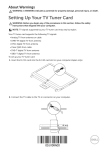
S-VSL6C
SPEAKER SYSTEM
OPERATING INSTRUCTIONS
Caution: in use
Thank you for buying this Pioneer product. Please read through these
operating instructions so you will know how to operate your model
properly. After you have finished reading the instructions, put them
away in a safe place for future reference.
Accessories
Speaker stand .................................................................................. 1
Mounting fixtures ............................................................................. 1
Safety wire ....................................................................................... 1
Anti-slip pads ........................................................................... 1 (set)
Speaker stand pads (3 types) .......................................................... 1
Screws ............................................................................................. 7
Washers ........................................................................................... 2
Self-adhering fastener (hook strip) .................................................. 2
Self-adhering fastener (loop strip) ................................................... 2
Operating Instructions ..................................................................... 1
Quick Tip
A speaker system's sound characteristics will change
depending on the environment and conditions under which the
system is. A speaker system can be used without problem
immediately after purchase, but its design performance
characteristics will be best demonstrated after breaking them
in by playing music for several dozen hours.
Before you start
• Don’t use the speakers to output distorted sound for long
periods of times. This can result in a fire hazard.
• Do not sit or stand on the speakers or let children play on the
speakers.
• Do not put large or heavy objects on top of the speakers.
Connecting Speakers to Amplifier
1 Disconnect the power cord to the amplifier.
2 Use speaker wire to connect the input terminals on the rear panel
of the speakers to the amplifier's speaker output terminals.
Connect the hot-side speaker wire to the + speaker output
terminal; connect the common-side speaker wire to the - speaker
output terminal.
1. Remove insulation at end of wire and twist
ends of wire strands.
2. Loosen the terminal screw and insert the
twisted wire into the hole, then tighten the
terminal screw securely.
When using the supplied speaker stand in a horizontal
installation, pass the speaker wire through the speaker
stand before connecting. When mounting vertically, pass
the wires through the mounting fixture before connecting.
<Horizontal Installation>
<Vertical Installation>
• The nominal impedance of this speaker system is 6 ohms.
Connect the speaker system to an amplifier with a load
impedance ranging from 4 to 16 ohms (a model with
“4 – 16 Ω” displayed on the speaker output terminals).
In order to prevent damage to the speaker system resulting from
input overload, please observe the following precautions:
• Do not supply power to the speaker system in excess of the
maximum permissible input.
• When connecting or disconnecting anything in your AV system,
make sure the amplifier is switched off.
• When using a graphic equalizer to emphasize loud sounds in
the high-frequency range, do not use excessive amplifier
volume.
• Do not try to force a low-powered amplifier to produce loud
volumes of sound (the amplifier’s harmonic distortion will be
increased, and you may damage the speaker).
Black Red +
Caution: installation
• Do not place the speakers on an unstable surface. It could
present a hazard if it falls, as well as damaging the equipment.
• Switch off and unplug your AV equipment and consult the
instructions when connecting up components. Make sure you
use the correct connecting cables.
• The speaker system grill cannot be removed. Do not try to
forcibly remove it since doing so may damage the grille.
Connect the commonside speaker wire to the speaker output terminal.
Connect the hot-side
speaker wire to the +
speaker output
terminal.
The speaker system's input terminals can also be
connected using a banana plug (only with horizontal
installation)
Installation example 2 (Vertical installation)
1. Affix mounting pad
• After connecting the wires to their speaker system terminals, pull
gently on the wires and confirm that the leads are fastened
securely to their terminals. Insecure connections will result in
broken sound and noise.
• Do not allow bare wire ends to protrude excessively from the
terminals. If bare wires from the two leads touch each other,
excessive load will be placed on the amplifier, leading to possible
damage or malfunction.
• Be sure to connect the + and – leads to their correct terminals. If
the poles at one end of the wires are connected mistakenly (+ to –,
– to +), proper stereo effect will not be produced.
Pad
2. Use 4 supplied screws to attach the accessory mounting fixture to
the speaker stand (Fig. a)
3. Use 2 supplied screws to attach the mounting fixture and speaker
stand to the speaker (Fig. b)
(Fig. a)
(Fig. b)
Rack Installation
Preparation
When mounting the speakers on a rack, use the supplied accessory
anti-slip pad or self-adhering fastener strips. The anti-slip pads may
not be fully effective on some surfaces; if any danger of tipping or
falling exists, do not attempt to mount the speakers in that position.
• Using anti-slip pads
Peel off the protective paper backing from the four anti-slip pads
and apply to the four bottom corners of the speaker stand.
Pay special attention to choosing a safe installation
location when mounting the speaker vertically, since it
may tend to tip over.
`
Anti-slip pads
Wall Mounting
• Using self-adhering fastener
1. Peel off the protective paper backing from the two loop strips
and apply to the bottom surface of the speaker stand.
2. Peel off the protective paper backing from the two hook strips
and apply to the surface of the installation surface in alignment
with the two loop strips on the speaker stand.
Self-adhering fastener
(loop strip)
Self-adhering fastener
(hook strip)
Installation
surface
Assembly
• This speaker system is supplied with a mounting fixture for wall
mounting. When using the speaker system in a wall installation,
take full precautions to prevent the speaker from falling.
• Check the wall location thoroughly to ascertain its ability to support
the weight of the speaker system.
• If you are unable to determine the structural strength of the wall,
consult a building professional before attempting to install the
speaker system on a wall.
• No screws or bolts are provided for use in a wall installation.
Supply your own threaded fasteners in accordance with the wall or
pillar's material structure and strength.
• Install only on a vertically plumb surface. Installation at an angle
may result in dangerous loosening of the fixture, causing a fall.
1. First decide on whether you will install the speakers vertically or
horizontally. Use commercially available threaded fasteners
(screws or bolts) to attach the accessory mounting fixtures to the
wall.
When installing the speakers horizontally, use two screws installed
at the two locations shown (left and right); when using a vertical
installation, place one screw in the center as shown.
Assembling the speaker stands requires use of a medium Phillips
screwdriver.
Connect speaker wires before assembly
Wall hanging screws (buy
commercially)
Installation example 1 (Horizontal installation)
1. Affix mounting pads
Pads
2. Use two supplied screws to fasten the speaker stand to the
speaker
2
Horizontal installation
Vertical installation
2. Loosen the screws slightly to allow the mounting fixture to be
removed.
3. Attach the speaker wire to the speaker.
4. Use one provided accessory screw and one washer to attach the
accessory safety wire to the speaker as shown.
5. Use two provided accessory screws to attach the speaker to the
mounting fixture.
6. Use a commercially available screw or bolt and one of the provided
accessory washers to connect the loose end of the safety wire to
the wall.
7. Align the speaker with the screws installed in step 1, and fasten to
the wall.
Installation Example 1 (Horizontal installation)
Safety wire
Frequency response and harmonic
distortion
Commercially
purchased screw
0°
22.5°
100
80
45°
Accessory screws
Washers
60
Installation Example 2 (Vertical installation)
Commercially
purchsed screw
Safety wire
40
20
Washers
0
10
100
1k
10 k
50 kHz
Specifications
Accessory
screws
Remark
• This speaker system is magnetically shielded. However,
depending on the installation location, color distortion may occur
if the speaker system is installed extremely close to the screen
off a television set. If this happens, turn off the television, then
turn it on again after 15 to 30 minutes. If the problem persists,
place the speaker system away from the television set.
Type ........................................ Fully enclosed (acoustic suspension)
bookshelf speakers with magnetic-shielded design
Speaker composition ........................................................ 2-way type
Woofer ................................................................... 8.3 cm cone x 2
Tweeter ................................................................. 2 cm dome type
Nominal impedance ...................................................................... 8 Ω
Frequency response .................................................... 90–40,000 Hz
Output level ............................................................... 86 dB / W (1 m)
Permissible input
Maximum power ................................................................... 130 W
Crossover frequency .............................................................. 4.0 kHz
External dimensions
Speaker only
Horizontal mount .......................... 350 (W) x 102 (H) x 80 (D) mm
With speaker stand
Horizontal mount ........................ 350 (W) x 126 (H) x 101 (D) mm
Vertical mount ............................ 102 (W) x 385 (H) x 103 (D) mm
Weight ........................................................................... 2.2 kg (each)
• Appearance and specifications subject to change without notice.
We Want You Listening For A Lifetime
Selecting fine audio equipment such as the unit you’ve just
purchased is only the start of your musical enjoyment. Now it’s
time to consider how you can maximize the fun and excitement
your equipment offers. This manufacturer and the Electronic
Industries Association’s Consumer Electronics Group want you
to get the most out of your equipment by playing it at a safe level.
One that lets the sound come through loud and clear without
annoying blaring or distortion-and, most importantly, without
affecting your sensitive hearing.
Sound can be deceiving. Over time your hearing “comfort
level” adapts to higher volumes of sound. So what sounds
“normal” can actually be loud and harmful to your hearing. Guard
against this by setting your equipment at a safe level BEFORE
your hearing adapts.
To establish a safe level:
Start your volume control at a low setting.
Slowly increase the sound until you can hear it comfortably and
clearly, and without distortion.
••
Used wisely, your new sound equipment will provide a lifetime
of fun and enjoyment. Since hearing damage from loud noise is
often undetectable until it is too late, this manufacturer and the
Electronic Industries Association’s Consumer Electronics Group
recommend you avoid prolonged exposure to excessive noise.
This list of sound levels is included for your protection.
Decibel
Level Example
30
Quiet library, soft whispers
40
Living room, refrigerator, bedroom away from traffic
50
Light traffic, normal conversation, quiet office
60
Air conditioner at 20 feet, sewing machine
70
Vacuum cleaner, hair dryer, noisy restaurant
80
Average city traffic, garbage disposals, alarm clock
at two feet.
THE FOLLOWING NOISES CAN BE DANGEROUS
UNDER CONSTANT EXPOSURE
90
Subway, motorcycle, truck traffic, lawn mower
100
Garbage truck, chain saw, pneumatic drill
120
Rock band concert in front of speakers, thunderclap
140
Gunshot blast, jet plane
180
Rocket launching pad
Information courtesy of the Deafness Research Foundation.
Once you have established a comfortable sound level:
Set the dial and leave it there.
•
Taking a minute to do this now will help to prevent hearing
damage or loss in the future. After all, we want you listening for
a lifetime.
3
www.pioneerelectronics.com
LIMITED WARRANTY
PIONEER ELECTRONICS (USA) INC.
PIONEER ELECTRONICS OF CANADA, INC.
WARRANTY PERIOD
For the period specified below from date of original retail purchase (the warranty period) from an authorized Pioneer dealer, Pioneer
Electronics (USA) Inc. (PUSA), and Pioneer Electronics of Canada, Inc. (POC) warrants that products distributed by PUSA in the U.S.A.,
and by POC in Canada that fail to function properly under normal use due to a manufacturing defect when installed and operated
according to the operating instructions enclosed with the unit will be repaired or replaced with a unit of comparable value, at the option
of PUSA or POC, without charge to you for parts or actual repair work. Parts supplied under this warranty may be new or rebuilt at the
option of PUSA or POC.
WARRANTY PERIOD
PRODUCT
PARTS
LABOR
Loudspeakers / Subwoofers (amplifier section not included) ......................................................... 1 YEAR
1 YEAR
Amplifier Section (if applicable) ........................................................................................................... 1 YEAR
1 YEAR
This warranty covers the product during the warranty period whether in the possession of the original owner or any subsequent owner.
In the event service is required, the product must be delivered within the warranty period, transportation prepaid, from within the Country
of purchase as explained in this document. You will be responsible for removal and installation of the product.
WHAT'S NOT COVERED
This warranty does not cover any product which is used in any trade or business, or in an industrial or commercial application.
This warranty does not apply to any speaker that has been subjected to power in excess of its published power rating.
This warranty does not cover the cabinet or any appearance item, any damage to the product resulting from alterations or modifications
not authorized in writing by PUSA or POC, accident, misuse or abuse, or damage due to lightning or to power surges.
This warranty does not cover the cost of parts or labor which would be otherwise provided without charge under this warranty obtained
from any source other than a PUSA OR POC Authorized Service Company or other designated location. This warranty does not cover
defects or damage caused by the use of unauthorized parts or labor, or from improper maintenance.
ALTERED, DEFACED OR REMOVED SERIAL NUMBERS VOID THIS WARRANTY.
YOUR RIGHTS
PUSA and POC excludes any obligation on its part for incidental or consequential damages related to the failure of products to function
properly under the conditions set forth above.
IN THE U.S.A. - PUSA LIMITS ITS OBLIGATIONS UNDER ANY IMPLIED WARRANTIES INCLUDING, BUT NOT LIMITED TO, THE
IMPLIED WARRANTIES OF MERCHANTABILITY AND FITNESS FOR A PARTICULAR PURPOSE, TO A PERIOD NOT TO EXCEED
THE WARRANTY PERIOD. NO WARRANTIES SHALL APPLY AFTER THE WARRANTY PERIOD. SOME STATES DO NOT ALLOW
LIMITATIONS ON HOW LONG AN IMPLIED WARRANTY LASTS, AND SOME STATES DO NOT ALLOW THE EXCLUSION OR
LIMITATION OF INCIDENTAL OR CONSEQUENTIAL DAMAGES, SO THE ABOVE LIMITATIONS OR EXCLUSIONS MAY NOT
APPLY TO YOU. THIS WARRANTY GIVES YOU SPECIFIC LEGAL RIGHTS, AND YOU MAY HAVE OTHER RIGHTS WHICH MAY
VARY FROM STATE TO STATE.
IN CANADA - EXCEPT AS EXPRESSLY PROVIDED HEREIN, THERE ARE NO REPRESENTATIONS, WARRANTIES, OBLIGATIONS OR CONDITIONS, IMPLIED, STATUTORY OR OTHERWISE, APPLICABLE TO THIS PRODUCT.
TO OBTAIN SERVICE
PUSA and POC have appointed a number of Authorized Service Companies throughout the U.S.A., and Canada should your product
ever require service. To receive warranty service you will need to present your sales receipt or, if rented, your rental contract showing
place and date of original owner's transaction. Should it become necessary to ship your unit, you will need to package the product
carefully and send it, transportation prepaid by a traceable, pre-insured method, to an Authorized Service Company. Carefully package
the product using adequate padding material to prevent damage in transit. The original container is ideal for this purpose. Include in
the package your name, address, telephone number where you can be reached during business hours, a copy of your sales receipt
and a detailed description of the problem. PUSA or POC, as appropriate, will pay for the cost of returning the repaired or replacement
product to you within the Country of purchase.
For additional information about this limited warranty or to locate the nearest PUSA or POC Authorized Service Company, please contact:
IN THE U.S.A.
CUSTOMER SERVICE DEPARTMENT
PIONEER ELECTRONICS (USA) INC.
P.O. BOX 1760
LONG BEACH, CA 90801 USA
Phone: 1-800-421-1404
IN CANADA
CUSTOMER SERVICE DEPARTMENT
PIONEER ELECTRONICS OF CANADA, INC.
300 ALLSTATE PARKWAY
MARKHAM, ON L3R OP2
Phone: 905-479-4411, 1-877-283-5901
DO NOT RETURN ANY PRODUCT TO THE ABOVE ADDRESSES. THEY ARE NOT SERVICE LOCATIONS.
RECORD THE PLACE AND DATE OF PURCHASE FOR FUTURE REFERENCE
Model No.: _____________________ Serial No.: _______________________
Purchase Date: ___________ Purchased From: ________________________
KEEP THIS INFORMATION AND YOUR SALES RECEIPT IN A SAFE PLACE
PIONEER CORPORATION
4-1, Meguro 1-Chome, Meguro-ku, Tokyo 153-8654. Japan
PIONEER ELECTRONICS (USA) INC.
P.O. BOX 1540, Long Beach, California 90801-1540
PIONEER ELECTRONICS OF CANADA, INC. 300 Allstate Parkway Markham, Ontario L3R OP2, Canada
PIONEER ELECTRONIC (EUROPE) N.V. Haven 1087 Keetberglaan 1,9120 Melsele, Belgium, TEL: 03/570.05.11
PIONEER ELECTRONICS AUSTRALIA PTY. LTD. 178-184 Boundary Road, Braeside, Victoria 3195, Australia, TEL: [03] 9586-6300
PIONEER ELECTRONICS DE MEXICO S.A. DE C.V. San Lorenzo Num 1009 3er piso Desp. 302 Col. Del Valle, Mexico D.F. C.P. 03100 TEL: 5-688-52-90
Printed in China <284426-A>
4
Published by Pioneer Corporation.
Copyright © 2004 Pioneer Corporation.
All rights reserved.