1
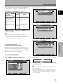
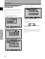
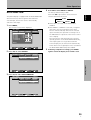
ビデオカード
VIDEO CARD
CARTE VIDEO
VIDEOKARTE
PDA-5002
取扱説明書
Operating Instructions
Mode d’emploi
Bedienungsanleitung
Contents
Safety Precautions .................................. i
English
Before Proceeding .................................. 2
How to Use This Manual .............................................. 2
Checking Supplied Accessories ................................... 3
Part Names and Functions .................... 4
Connection Panel .......................................................... 4
Installation and Connections ................ 6
Installing the Video Card .............................................. 6
Input Connectors on the Plasma Display with
Video Card ..................................................................... 7
Connection to INPUT1 and INPUT2 ............................. 7
Connection to INPUT3 ................................................ 10
Connection to INPUT4 ................................................ 10
Connection to INPUT5 ................................................ 11
About DTV set Top Box Connection .......................... 11
Audio Connections ...................................................... 12
How to Route Cables ................................................... 13
Setting Up the System ........................ 14
Setup after Connection ............................................... 14
Operations ............................................ 16
PartBefore
NamesProceeding
and Functions
Selecting an Input Source .......................................... 16
Screen Size Selection .................................................. 18
Partial Image Enlargement (POINT ZOOM) .............. 19
Automatic Power OFF ................................................. 20
Display Panel Adjustments ................. 21
Adjusting the Picture Quality ..................................... 21
Adjusting the Image Position and Clock
(Automatic Adjustment) ............................................. 22
Manual Adjustment of Screen Position and
Clock ............................................................................. 22
Other Operations ................................. 24
Rewriting the Input Display (INPUT LABEL) ............. 24
Changing the Color Temperature
(COLOR TEMP) ............................................................ 25
Reducing Video Noise (DIGITAL NR) ......................... 25
Setting the PureCinema Mode ................................... 26
Setting the Regional TV System Format ................... 26
Viewing a Fast Moving Picture
(3D Y/C MODE) ............................................................ 27
Viewing in a Bright Location
(HIGH CONTRAST) ...................................................... 28
AUTO FUNCTION ........................................................ 29
Audio Output (AUDIO OUT) ....................................... 30
Additional Information ........................ 31
Specifications .............................................................. 31
Supplement 1 .............................................................. 32
Supplement 2 .............................................................. 32
Supplement 3 .............................................................. 33
Explanation of Terms .................................................. 33
2
En
Before Proceeding
How to Use This Manual
This manual has been written to allow easy understanding
of setup and operating procedures when the video card
PDA-5002 is installed in the plasma display.
Remove the video card from its packaging and confirm
that all accessory parts are present. While installing and
setting up the video card, consult the section “Part
Names and Functions” on page 4 of this manual and in
the plasma display’s Operating Instructions to familiarize
yourself with the parts of the respective devices. Since
this manual makes frequent reference to the names of
operating buttons on the plasma display, use the display’s
Operating Instructions to familiarize yourself with the
controls on the display and the remote control unit.
The section “Installation and Connections” on page 6
includes information necessary for installing the video
card on the plasma display, together with instructions
regarding connections to various other components.
The section “Setting Up the System” starting on page 14
covers the necessary on-screen menu settings to
establish correct linkage between the plasma display and
connected components. Depending on the connections
made, this section may or not be necessary.
The remainder of the sections in this manual is dedicated
to the basic operations associated with selecting a source
component up to the more complex operations
associated with adjusting the plasma display picture to
match the requirements of specific components and
personal preferences.
About operations in this manual
Operations in this manual are outlined in step by step
numbered procedures. Most of the procedures are
written in reference to the remote control unit unless the
button or control is only present on the main unit.
However, if a button or control on the main unit has the
same or similar name as that on the remote control unit,
that button can be used when performing operations.
The following example is an actual operation that shows
how one might set the horizontal and vertical positions of
the screen. The screens shown at each step are provided
as a visual guide to confirm that the procedure is
proceeding as it should. Please familiarize yourself with
this process before continuing on with the rest of this
manual.
Note
The screen displays depicted in this manual represent typical
display examples.
The actual items and contents seen in screen displays may vary
depending on input source and specific settings.
Before Proceeding
Press MENU to display the menu screen.
MAIN MENU
INPUT1
PICTURE
SCREEN
:
CO NT RA S T
0
:
BR I GHT .
0
: +60
R. L E V E L
:
+60
G. L E V E L
: +60
B. L E V E L
:
0
H . E NH AN CE
:
V . E NH AN CE
0
SET UP
Checking Supplied Accessories
OPTION
English
1
Check that the following accessories were supplied.
1 Label for remote control unit
RE S E T
SELECT
ENTER
MENU
EXIT
2 BNC/Pin conversion adaptor
Press 3 to select SCREEN.
MAIN MENU
PICTURE
INPUT1
SCREEN
:
POS I T I ON
CL OC K / P HA S E :
SET UP
0 /
0 /
OPTION
0
0
RE S E T
3 Connector indicator label
INPUT5
DIGITAL RGB
SELECT
3
SET
ENTER
MENU
Press 5/∞ to select the item to be adjusted.
MAIN MENU
PICTURE
INPUT1
SCREEN
:
POS I T I ON
CL OC K / P HA S E :
SET UP
0 /
0 /
INPUT3
R
AUDIO
L
INPUT4
S-VIDEO
R
AUDIO
L
VIDEO
OUTPUT
EXIT
4 Screws (×2)
(Accessory screws for installing video card)
OPTION
0
0
PartBefore
NamesProceeding
and Functions
2
SET
RE S E T
÷
÷
SELECT
4
SET
ENTER
EXIT
Press SET to display the adjustment screen for the
selected item.
H. P O S I T I O N :
V. POS I T I ON :
ADJUST
5
MENU
Operating Instructions
Warranty
MENU
SET
0
0
EXIT
SET
Press 5/∞/2/3 to adjust the value.
3
En
Part Names and Functions
Connection Panel
English
AC INLET
INPUT5
AUDIO
DIGITAL RGB
R
!
R
8Ω ~16Ω
SPEAKER
+
—
1
CONTROL
IN
OUT
2
L
INPUT4 VIDEO
AUDIO
R
4
Plasma Display Section
The plasma display is provided with 2 video input
connectors, 1 video output connector, audio input/output
jacks and speaker terminals.
There are also CONTROL IN/OUT jacks for connection of
PIONEER components with the Î mark.
When this video card is installed on a plasma display, an
additional three sets of video input connectors are
provided (total five), together with one additional video
output connector (total two). See the pages noted in
parentheses ( ) or the plasma display’s Operating
Instructions for details regarding connections to the
various jacks and connectors.
L
~
OUTPUT
L
% ^
INPUT1
RS-232C
OUT
3
=
@ # $
COMBINATION
IN
INPUT3 S-VIDEO
—
ON
-
Part Names and Functions
8Ω ~16Ω
SPEAKER
+
OFF
(ON SYNC)
ANALOG RGB
OUTPUT
(ANALOG RGB)
5
6
G
B
INPUT2 (H/V SYNC)
R
HD
AUDIO
INPUT
OUTPUT
VD
75Ô 2.2
Ω
kΩ
7
(INPUT1/2)
89 0
4 RS-232C
DO NOT MAKE ANY CONNECTIONS TO THIS
TERMINAL.
This terminal is used in the factory setup.
5 INPUT1 (mini D-sub 15 pin)
For connection of components that have RGB or
component output jacks such as a personal
computer, DVD player, or external RGB decoder.
Make sure that the connection made corresponds to
the format of the signal output from the connected
component (pages 7 to 10).
6 OUTPUT (INPUT1)
1 SPEAKER (R) terminal
For connection of an external right speaker.
Connect a speaker whose impedance is 8 -16 Ω.
2 CONTROL IN/OUT (monaural mini jacks)
For connection of PIONEER components that bear the
Î mark. Making CONTROL connection enables
control of the plasma display as a component in a
system.
3 COMBINATION IN/OUT
DO NOT MAKE ANY CONNECTIONS TO THESE
TERMINALS.
These terminals are used in the factory setup.
4
En
(mini D-sub 15 pin)
Use the OUTPUT (INPUT1) connector to output the
video signal to an external monitor or other
component.
Note: The video signal will not be output from the
OUTPUT (INPUT1) connector when the main power of
this display is off or in standby mode.
(page 10)
7 INPUT2 (BNC jacks)
For connection of components that have RGB or
component output jacks such as a personal computer,
DVD player, or external RGB decoder. Make sure that
the connection made corresponds to the format of the
signal output from the connected component (pages 7
to 9).
Part Names and Functions
9 AUDIO INPUT (Stereo mini jack)
Use to obtain sound when INPUT1, INPUT2 or
INPUT5 is selected.
Connect this jack to the audio output connector of the
device connected to the plasma display’s INPUT1 or
INPUT2, or to the audio output connector of the
device connected to the video card’s INPUT5 (page
12).
0 AUDIO OUTPUT (Stereo mini jack)
Use to output the audio of the selected source
component connected to the plasma display to an AV
amplifier or similar component (page 12).
- MAIN POWER switch
Use to switch the main power of the plasma display
on and off.
= AC INLET
A power cable is furnished with the plasma display;
connect one end of the power cable to this connector,
and the other end to a standard AC power source.
~ SPEAKER (L) terminal
For connection of an external left speaker. Connect a
speaker that has an impedance of 8 -16 Ω.
Video Card <PDA-5002> Section
The video card is provided with 3 video input connectors,
1 video output connector, and 2 audio input connectors.
Consult the pages noted in parentheses ( ) for details
regarding connections to the various jacks and
connectors.
English
Depending on the connections made at INPUT2, it
may be necessary to set this switch to match the
output impedance of the connected component’s
synchronization signal.
When the output impedance of the component’s
synchronization signal is above 75 Ω, set this switch
to the 2.2 kΩ position (page 9).
! INPUT5 (DVI-D jack)
Use to connect a computer.
Note: This unit does not support the display of
copyguard-protected video signals (page 11).
@ AUDIO INPUT3 (RCA Pin jacks)
Use to obtain sound when INPUT3 is selected.
Connect these jacks to the audio output connectors of
components connected to the video card’s INPUT3
(page 12).
Note: The left audio channel (L) jack is not compatible
with monaural input sources.
# INPUT3 (S-video jack)
For connection of components that have an S-video
output jack such as a video deck, video camera, laser
disc player, or DVD player. (page 10)
$ AUDIO INPUT4 (RCA Pin jacks)
Use to obtain sound when INPUT4 is selected.
Connect these jacks to the audio output connectors of
components connected to the video card’s INPUT4
(page 12).
Note: The left audio channel (L) jack is not compatible
with monaural input sources.
% INPUT4 (BNC jack)
For connection of components that have a composite
video output jack such as a video deck, video camera,
laser disc player, or DVD player (page 10).
^ OUTPUT (INPUT4) (BNC jack)
Use the OUTPUT (INPUT4) jack to output the video
signal to an external monitor or other component.
Note: The video signal will not be output from the
OUTPUT (INPUT4) jack when the main power of this
display is off or in standby mode (page 10).
5
En
Part Names and Functions
8 Synchronizing signal impedance selector switch
Installation and Connections
English
Installing the Video Card
2
Insert the video card gently and evenly in
alignment with the two rails (black) visible inside
the installation port.
TO USERS:
Note
This component is sold with the understanding that it will
be installed by a specialist possessing appropriate
technical knowledge and ability.
Be very careful when inserting the card. Insert straight!
The card or display may be damaged if the card is inserted
crooked or with excessive force.
TO SALES AGENTS:
Installation instructions are noted below. When installing
the unit, if a screw or other object should drop inside the
plasma display, immediately consult your nearest Pioneer
Service Center. Continuing operation may result in
malfunction.
This device has been designed for installation on the
Pioneer Plasma Display PDP-503CMX/PDP-503MXE.
Installation procedures are as follows:
INPUT5
DIGITAL RGB
3
AUDIO
INPUT3
Installation and Connections
÷ When opening the installation cover, take care not to drop
screws or other objects in the opening. Objects dropped inside
the display may cause damage or malfunction.
÷ When installing the video card, if the plasma display is laid
with its screen side facing down, the work surface should be
flat and level, and either the packing material, a blanket, or
other soft material should be spread on the work surface first
to protect the screen. Take care to prevent scratches or other
damage to the unit from tools or other objects. Never rest the
display on a surface in such a way that weight or pressure is
placed only on the screen surface.
÷ This video card has been designed for exclusive use with the
Pioneer Plasma Display PDP-503CMX/PDP-503MXE. Do not
attempt unauthorized modifications or alterations since
malfunction or damage may result.
÷ Take care not to modify or damage the card's internal devices
in any way.
÷ Before installation, take precautions to eliminate static
electricity on your body. Do not touch the card's circuitry or
devices.
÷ This device has not been designed to allow reinstallation or
removal; after the card has once been installed on the plasma
display, do not attempt to remove it since damage may result.
4
OUTPUT
S-VIDEO
INPUT3
AUDIO
AUDIO
INPUT4
VIDEO
INPUT3
S-VIDEO
AUDIO
OUTPUT
INPUT4
INPUT3
INPUT5
DIGITAL RGB
R
AUDIO
L
VIDEO
OUTPUT
INPUT4
S-VIDEO
R
AUDIO
L
VIDEO
OUTPUT
Note
Use a soft cloth to gently wipe any dust
from the surface before affixing the label.
Video Card Removal (In principle, removal of
the video card should not be attempted).
1
Remove the two screws holding the video card.
AUDIO
INPUT5
DIGITAL RGB
INPUT3
S-VIDEO
AUDIO
INPUT4
VIDEO
OUTPUT
Remove the protective cover over the video card
slot on the plasma display’s terminal panel.
Holding the inside tabs, pull the video card out
straight.
INPUT5
DIGITAL RGB
En
VIDEO
Affix the accessory connector indicator label to the
plasma display, and affix the remote control unit
label to the remote control unit furnished with the
plasma display.
INPUT5
DIGITAL RGB
2
6
INPUT4
AUDIO
INPUT5
DIGITAL RGB
Installation
1
AUDIO
After inserting the video card all the way into the
slot, confirm that it is seated securely, then use
the screws removed in step 1 to secure the card in
place.
Confirm the following before installing this video card:
• Disconnect the plasma display from computer or other
components.
• Disconnect the plasma display’s power cord from its
outlet.
Installation Notes:
S-VIDEO
AUDIO
INPUT3
S-VIDEO
AUDIO
INPUT4
VIDEO
OUTPUT
Installation and Connections
Connection to INPUT1 and INPUT2
Consult the following chart when making connections to
a plasma display equipped with this video card (pages 7
to 12).
Input
Connector INPUT INPUT INPUT INPUT INPUT
Connected
1*1
2*1
3
4
5
component
and signals
AV component
Various components can be connected to the INPUT1 and
INPUT2 jacks. After connections are made, on-screen
setup is necessary to match the characteristics of the
connected component. Please see pages 14 and 15 for
on-screen setup after connection.
INPUT2
jack
Component video
Composite video
Personal computer
(PC)
Digital RGB
R
B
R
G
B
R
H/V SYNC
G
B
R
HD
*3
VD
Y
VD
CB/PB CR/PR
*3
*4
*1 Although INPUT1/INPUT2 are compatible with various kinds
of signals, setup using the on-screen menu is necessary after
connections are made in order match the characteristics of
the source component (pages 14 and 15).
*2 INPUT1 is compatible with Microsoft’s Plug & Play (VESA
DDC 1/2B).
*3 Depending on the video output board of the computer, this
type of connection may not be possible.
*4 INPUT5 is compatible with Microsoft’s Plug & Play (VESA
DDC 2B).
: Do not connect anything.
: Connect to this jack.
Note
Components compatible with INPUT1 are also compatible with
INPUT2.
When making connections to INPUT1, please refer to the plasma
display’s Operating Instructions.
Installation and Connections
Composite video
Video component
with component
video output
*2
[H/V SYNC]
HD
B
Output source
S video
S video
G
Video component/
personal
G ON SYNC
computer (PC)
with RGB output
Analog RGB
Analog RGB
[ON SYNC]
English
Input Connectors on the Plasma
Display with Video Card
For the screen sizes and input signals that INPUT1
and INPUT2 are compatible with, please refer to
the plasma display’s Operating Instructions.
7
En
Installation and Connections
English
Connection to AV components
Connection to AV component that has
component video jacks
Make component video connections for AV components
such as DVD and LD players or similar components with
component video output capability.
Connection of G ON SYNC analog RGB source
Make G ON SYNC connections for a component with
output that has the synchronization signal layered on top
of the green signal.
When connecting to INPUT1
INPUT1
ANALOG RGB
OUTPUT
(ANALOG RGB)
When connecting to INPUT1
INPUT1
ANALOG RGB
OUTPUT
(ANALOG RGB)
On screen setup is necessary after connection.
Please see pages 14 and 15.
Installation and Connections
On-screen setup is necessary after connection.
Please see page 14.
When connecting to INPUT2
When connecting to INPUT2
(ON SYNC)
G
B
INPUT2 (H/V SYNC)
R
HD
VD
75Ô 2.2
Ω
kΩ
(ON SYNC)
G
B
INPUT2 (H/V SYNC)
R
HD
VD
75Ô 2.2
Ω
kΩ
Connect the Y signal to the G jack, the CB/PB signal to the
B jack, and the CR/PR signal to the R jack.
On-screen setup is necessary after connection.
Please see page 14.
INPUT2 jacks are all BNC jacks.
If necessary, use BNC/pin conversion adapters (1 (one)
included) to make connections.
8
En
On screen setup is necessary after connection.
Please see pages 14 and 15.
Note
When making G ON SYNC connections, do not make any
connections to the VD or HD jacks. If connections are made, the
picture may be not displayed normally.
Installation and Connections
Make composite SYNC connections for a component
with output that has the vertical synchronization signal
layered on top of the horizontal synchronization signal.
Connection to a personal
computer
English
Connection of composite SYNC analog RGB
source
Connection method differs depending on the computer
type. When connecting, please thoroughly read the
computer’s instruction manual.
When connecting to INPUT1
Before making connections, be sure to make sure that
the personal computer’s power and display’s main power
is off.
INPUT1
ANALOG RGB
OUTPUT
(ANALOG RGB)
For the PC input signals and screen sizes that the display
is compatible with, please refer to the plasma display’s
Operating Instructions.
Connection of separate SYNC analog RGB
source
Make separate SYNC connections for a personal
computer that has RGB output separated into 5 output
signals: green, blue, red, horizontal synchronization signal,
and vertical synchronization signal.
When connecting to INPUT2
On-screen setup is necessary after connection.
Please see pages 14 and 15.
(ON SYNC)
G
B
INPUT2 (H/V SYNC)
R
HD
VD
75Ô 2.2
Ω
kΩ
When connecting to INPUT2
G
B
INPUT2 (H/V SYNC)
R
HD
VD
Installation and Connections
(ON SYNC)
75Ô 2.2
Ω
kΩ
When using INPUT2, set the impedance selector switch
to match the output impedance of the connected
component’s synchronization signal.
When the output impedance of the component’s
synchronization signal is above 75 Ω, set this switch to
the 2.2 kΩ position.
On-screen setup is necessary after connection.
Please see pages 14 and 15.
When using INPUT2, set the impedance selector switch
to match the output impedance of the connected
computer’s synchronization signal.
When the output impedance of the computer’s
synchronization signal is above 75 Ω, set this switch to
the 2.2 kΩ position.
On-screen setup is necessary after connection.
Please see pages 14 and 15.
Notes
÷ When making composite SYNC connections, do not connect
anything to the VD jack. If connected to, the picture may not
be displayed properly.
÷ On some types of Macintosh® components, G ON SYNC and
composite SYNC are both output. With this type of
component, please connect using the G ON SYNC connection
(as shown left).
9
En
Installation and Connections
When connecting to INPUT1
Connection to INPUT3
INPUT1
English
ANALOG RGB
OUTPUT
(ANALOG RGB)
Connect an AV component that has S-video output jack to
the video card’s S-VIDEO input jack.
AUDIO
INPUT3 S-VIDEO
R
L
Connect the cable corresponding to the shape of the
input terminal on the display and the personal computer’s
output terminal.
Secure by tightening the terminal screws on both units.
AV component
After connecting, on-screen setup is necessary.
Please see pages 14 and 15.
Connection to INPUT4
Installation and Connections
Note
Depending on the type of computer model being connected, a
conversion connector or adapter etc. provided with the computer
or sold separately may be necessary.
For details, please read your PC’s instruction manual or consult
the maker or nearest dealer of your computer.
When connecting to OUTPUT (INPUT1)
Connect an AV component that has a video output jack to
the video card’s INPUT4 jack. The OUTPUT [INPUT4] jack
can be used to output the video signal to a separate
monitor, recording device or other component with video
input capability.
Note
A video signal will not be output from the OUTPUT [INPUT4] jack
when the main power of this display is off or in standby mode.
INPUT1
ANALOG RGB
OUTPUT
(ANALOG RGB)
INPUT4 VIDEO
AUDIO
R
To an external monitor
OUTPUT
L
To a monitor or a
recording device
With the plasma display, it is possible to output the video
signal to an external monitor or other component from
the OUTPUT (INPUT1) terminal.
Note
A video signal will not be output from the OUTPUT (INPUT1)
terminal when the main power of this unit is off or in standby.
AV component
Signals to the INPUT3 and INPUT4 jacks are all
compatible with the following TV systems: NTSC, PAL,
SECAM and 4.43NTSC. For details, please refer to
“Setting the regional TV system format” on pages 2627.
10
En
Installation and Connections
A computer equipped with DVI output (digital RGB signal)
can be connected to the video card’s DVI connector.
INPUT5
DIGITAL RGB
NOTICE
¶ INPUT 5 supports Microsoft “Plug & Play” (VESA DDC 2B)
components. See Supplement 3 (page 33) when making
connections to INPUT 5.
¶ See Supplement 2 (page 32) for information regarding signals
and display formats supported by INPUT 5.
English
Connection to INPUT5
Personal computer
Following completing connections, on-screen setup is
necessary. See page 14 for details.
Notes
Installation and Connections
¶ Use a DVI-D 24-pin (digital only) cable for the connection.
¶ This unit does not support the display of copyguardprotected video signals.
About DTV Set Top Box Connection
To ensure proper connection, please carefully read the
instruction manual supplied with the DTV set top box.
The set top box output signals that this display is
compatible with are as follows.
Video
signal type
HDTV
SDTV
Video signal
Video
signal format
1125i (1080i)
1125p (1080p)
750p (720p)
Component
525i (480i)
625i (575i)
Composite
Jacks where connection is possible
INPUT1 INPUT2 INPUT3 INPUT4
RGB
S Video
Component
RGB
525p (480p)
625p (575p)
Component
RGB
11
En
Installation and Connections
Audio connection for component connected to
INPUT3
English
Audio Connections
Before making connections, be sure to check that the
audio component’s power and the display’s main power is
off.
AUDIO
R
INPUT3 S-VIDEO
L
Connect an audio component to the audio input
jack of the plasma display with installed video
card.
When the video card is installed, the plasma display
provides three audio input jacks and one audio output
jack. Consult the following chart to choose the proper
audio input for each video input.
Video
input
INPUT1
INPUT2
Audio input jacks
Stereo mini jack
(L/R)
INPUT5
INPUT3
Pin jacks (L/R)
INPUT4
Pin jacks (L/R)
Sound output
Sound of the selected video
input is output from the
• SPEAKER terminals
• Stereo mini jacks (L/R).
Audio connection for component connected to
INPUT1, INPUT2 or INPUT5
Audio input to the AUDIO INPUT3 jacks (pin jacks (L/R)) is
possible for a component connected to INPUT3.
Sound is output from both the AUDIO OUTPUT jack
(stereo mini jack (L/R)) and the SPEAKER terminals
according to the video input selection.
Audio connection for component connected to
INPUT4
AUDIO
INPUT
OUTPUT
VD
75Ô 2.2
Ω
kΩ
(INPUT1/2)
INPUT4 VIDEO
AUDIO
OUTPUT
L
Installation and Connections
R
Of the audio sources connected to INPUT1, INPUT2 and
INPUT5, one can be used to connect a stereo mini-jack (L/
R) type plug.
Sound is output from both the AUDIO OUTPUT jack
(stereo mini jack (L/R)) and the SPEAKER terminals
according to the video input selection.
12
En
Audio input to the AUDIO INPUT4 jacks (pin jacks (L/R)) is
possible for a component connected to INPUT4.
Sound is output from both the AUDIO OUTPUT jack
(stereo mini jack (L/R)) and the SPEAKER terminals
according to the video input selection.
Installation and Connections
English
How to Route Cables
Speed clamps and bead bands are included with the
plasma display for bunching cables together. Once
components are connected, follow the following steps to
route cables.
* As viewed from the rear of the display.
1
2
time and may be damaged when removed.
Organize cables together using the provided
speed clamps.
Insert 1 into an appropriate hole on the rear of the
unit, then snap 2 into the back of 1 to fix the clamp.
2 Bunch separated cables together and secure
them with the provided bead bands.
Installation and Connections
1
Note
Cables can be routed to the right or left.
Speed clamps are designed to be difficult to undo
once in place. Please attach carefully.
To attach the speed clamps to the display
Connect the speed clamps using the 4 holes marked
with • below, depending on the situation.
To remove speed clamps
Using pliers, twist the clamp 90° and pull it outward.
In some cases the clamp may have deteriorated over
13
En
Setting Up the System
7
English
Setup after Connection
Press 2/3 to select the display mode.
After components have been connected to INPUT1,
INPUT2 or INPUT5, on-screen setup is necessary.
Follow the procedure described below and make settings
as they apply to the type of components connected.
Setting the Screen Mode /
Input Signal Format
1
2
3
4
S E T T I N G : V GA
Switch MAIN POWER on the connection panel to
the on position to turn on the display’s main
power.
The STANDBY/ON indicator lights red.
Press STANDBY/ON to put the display in the
operation mode.
The STANDBY/ON indicator turns green.
Select INPUT1, INPUT2 or INPUT5.
Press MENU to display the menu screen.
The menu screen appears.
MAIN MENU
PICTURE
CO NT RA S T
BR I GHT .
C O L OR
T I NT
S H A RP
SELECT
VIDEO
VGA
WIDE VGA
When using INPUT5:
VGA
OPTION
WIDE VGA
2 When the input signal has a refresh rate of 48.4
kHz horizontal / 60 Hz vertical, or 56.5 kHz
horizontal / 70 Hz vertical, pressing 2/3 will cause
the display mode to change alternately as follows:
RE S E T
XGA
Setting Up the System
EXIT
MENU
When a component other than a personal computer is
connected, set to “VIDEO”.
1 When the input signal has a refresh rate of 31.5 kHz
horizontal / 60 Hz vertical, pressing 2/3 will cause
the display mode to change alternately as follows:
When using INPUT1 or INPUT2:
INPUT1
SET UP
:
0
:
0
:
0
:
0
:
0
SET
SET
WIDE XGA
Note
SELECT
5
SET
ENTER
EXIT
MENU
Press 2/3 to select SET UP.
MAIN MENU
PICTURE
INPUT1
SET UP
OPTION
I N P UT L A B E L
AUT O P O WER OF F
D I G I T A L NR
H I GH C O N T R A S T
P URE C I N E M A
C L AM P P O S I T I O N
SETT I NG
V I DE O S I GNA L
: I N P UT 1
: OF F
: L OW
: OF F
: OF F
: AU T O
: V I DE O
: RGB
Setup steps 6-7 are required only when using signals with the
following refresh rates: 1 31.5 kHz horizontal / 60 Hz vertical; 2
48.4 kHz horizontal / 60 Hz vertical, or 56.5 kHz horizontal / 70 Hz
vertical. No manual setup is necessary for signals with other
refresh rates, since adjustments are performed automatically (the
SETTING item will not be displayed).
8
When VIDEO is selected, press 5/∞ to select
VIDEO SIGNAL.
MAIN MENU
PICTURE
SELECT
6
SET
ENTER
Press 5/∞ to select SETTING, then press SET.
MAIN MENU
PICTURE
INPUT1
SET UP
OPTION
I N P UT L A B E L
AUT O P O WER OF F
D I G I T A L NR
H I GH C O N T R A S T
P URE C I N E MA
C L AM P P O S I T I O N
SETT I NG
V I DE O S I GNA L
EXIT
MENU
INPUT1
SET UP
OPTION
I N P UT L A B E L
AUT O P O WER OF F
D I G I T A L NR
H I GH C O N T R A S T
P URE C I N E MA
C L AM P P O S I T I O N
SETT I NG
V I DE O S I GNA L
: I N P UT 1
: OF F
: L OW
: OF F
: OF F
: AU T O
: V I DE O
: RGB
SELECT
9
SET
CHANGE
14
En
SET
ENTER
MENU
EXIT
MENU
EXIT
Press SET repeatedly to select the input signal
format.
Selection will change as follows each time SET is
pressed.
RGB
SELECT
: I N P UT 1
: OF F
: L OW
: OF F
: OF F
: AU T O
: V I DE O
: RGB
COMPONENT
Setting Up the System
2
Press 2/3 to select SET UP.
MAIN MENU
PICTURE
Set SETTING and VIDEO SIGNAL as follows.
SET UP
Component video output
of a DVD player, etc.
VIDEO
COMPONENT
RGB video output of a
video deck etc., with RGB
output
VIDEO
RGB
RGB video output of a PC
Not supported
VGA
WIDE VGA
XGA
WIDE XGA
SET UP
I N P UT L A B E L
POWE R M A NA GEME NT
C L AMP P O S I T I O N
SETT I NG
SIGNAL
SETTING
Connected
component
INPUT1
SCREEN
SELECT
3
SET
OPTION
English
The table below shows what settings are appropriate
and available for the type of connections made.
: I N P UT 1
: OF F
: AU T O
: V GA
ENTER
EXIT
MENU
Press 5/∞ to select CLAMP POSITION.
MAIN MENU
PICTURE
INPUT1
SCREEN
SET UP
I N P UT L A B E L
POWE R M A NA GEME NT
C L A MP P O S I T I O N
SETT I NG
10 When the setup is completed, press MENU to exit
OPTION
: I N P UT 1
: OF F
: AUTO
: V GA
the menu screen.
Notes
÷ Make this setup for each input (INPUT1 and INPUT2).
÷ The VIDEO SIGNAL setting is not supported when inputting a
computer signal, or when the SETTINGS function has been
used to select a signal other than VIDEO.
SELECT
CHANGE
EXIT
MENU
Press SET to select LOCKED.
MAIN MENU
PICTURE
INPUT1
SCREEN
SET UP
I N P UT L A B E L
POWE R M A NA GEME NT
C L A MP P O S I T I O N
SETT I NG
CLAMP POSITION setup
OPTION
: I N P UT 1
: OF F
: L O CK E D
: V GA
Setting Up the System
4
SET
Depending on the signal, analog RGB signals may result
in the screen image appearing with a whitish or greenish
cast. In such cases, set “CLAMP POSITION” to LOCKED.
¶ Normally, leave this setting at AUTO.
SELECT
SET
CHANGE
MENU
EXIT
Setup of CLAMP POSITION
1
Mode selection will change as follows each time SET
is pressed.
Press MENU to display the menu screen.
The menu screen appears.
MAIN MENU
PICTURE
SCREEN
:
CO NT RA S T
0
:
BR I GHT .
0
: +60
R. L E V E L
: +60
G. L E V E L
: +60
B. L E V E L
:
0
H . E NH AN CE
:
V . E NH AN CE
0
SET UP
SET
LOCKED 2
OPTION
5
When the setup is completed, press MENU to exit
the menu screen.
Notes
÷ Make this CLAMP POSITION setting for each applicable input
(INPUT1 and INPUT2).
RE S E T
SELECT
3 AUTO
INPUT1
ENTER
MENU
EXIT
÷ When using this setup, be sure to carefully check the signal
output of the component that you are using. For details, please
refer to the instruction manual supplied with the component
you are connecting.
15
En
Operations
3
English
Selecting an Input Source
This section explains the basic operation of the plasma
display. Outlined on the following pages is how to turn
the main power on and off, put this display in the
operation or standby mode and how to select connected
components.
Press INPUT on the remote control unit or the
display to select the input.
Input changes each time the display’s INPUT is
pressed as follows.
3 INPUT1
3 INPUT2
INPUT5 2
3 INPUT3
INPUT4 2
• When the menu screen is displayed, changing the
signal input will cause the menu screen to turn off.
• If the input computer signal is not supported by the
display, the following message will be displayed:
Before you begin, make sure you have:
• Made connections between the plasma display and AV
components or personal computer as described in the
section “Installation and Connections” starting on page 6.
• Set up the on-screen menu to input signals from
components connected to INPUT1, INPUT2 and
INPUT5 as described in the section “Setting Up the
System” on page 14.
If no connections are made to these terminals,
on-screen setup is not necessary.
I NPUT 1
CA U T I O N
U N S UP P O R T E D S I G N AL
fH:
fV:
7 7. 1 kH z
85. 0 H z
1 15 2X 864
FUL L
I NPUT 1
2,5
2,5
3
3
CA U T I O N
OU T OF R A N G E
f H : 7 5. 7 kH z
f V : 1 20. 0 H z
Operations
––––
FUL L
4
Use VOLUME +/– on the remote control unit to
adjust the volume.
If no audio connections are made to the plasma
display, this step is not necessary.
5
When viewing is finished, press STANDBY/ON to
put the display in standby mode.
The STANDBY/ON indicator will blink and then remain
lit (red) indicating that the standby mode is engaged.
Operation is not possible while the STANDBY/ON
indicator is blinking (red).
6
Switch MAIN POWER on the display to the off
position to turn the main power off.
The STANDBY/ON indicator may continue to light for a
short while even after the main power is turned off.
This is a result of residual electric load impressed on
the circuitry, and the light will turn off presently.
4
Display Operating
Panel
Remote Control Unit
1
Switch MAIN POWER on the display to the on
position to turn the main power on.
The STANDBY/ON indicator lights red.
2
Press STANDBY/ON to put the plasma display in
the operation mode.
The STANDBY/ON indicator turns green.
CAUTION
16
En
Please do not leave the same picture displayed on the screen for
a long time. Doing so may cause a phenomenon known as
“screen burn” which leaves a ghost, or residual, image of the
picture on the screen.
Operations
To confirm display settings
English
To adjust the volume
DISPLAY
VOLUME +/–
Press VOLUME on the remote control unit.
Use VOLUME + or VOLUME – to adjust the volume of
the connected speakers.
Press DISPLAY on the remote control unit.
The currently selected input, screen size and refresh rates
will be displayed for about 3 seconds.
:
I NPUT 1
5
To mute the sound
fH:
fV:
Operations
V O L U ME
3 1. 5 kH z
60. 0 H z
64 0X 480
D O T BY D OT
MUTING
Note
The displayed refresh rates may be slightly different from the
actual values.
Press MUTING on the remote control unit.
Press MUTING again to restore the sound.
Muting is automatically canceled about 8 minutes after
the button is pressed, and the volume level is adjusted to
the minimum level.
Press VOLUME + or VOLUME – to adjust the volume at
a desired level.
17
En
Operations
English
Notes
Screen Size Selection
÷ When the WIDE, ZOOM, or FULL setting is used to display a
non-wide screen 4:3 picture fully on a wide screen, a portion
of the picture may be cut off or appear deformed.
The plasma display incorporates screen modes of various
height and width ratios. For optimal viewing, we
recommend that you select the screen mode that best
matches the video source that you are viewing. Although
these modes are designed for full display of a picture on a
wide screen, it is our hope that you make use of them
with a full understanding of the manufacturer’s intentions.
÷ Be aware that when the display is used for commercial or
public viewing purposes, selecting the WIDE, ZOOM or FULL
mode settings may violate the rights of authors protected
under copyright law.
Changing the screen size
When a vista size movie etc., is viewed at the ZOOM
setting, the image may not be centered on the screen,
and may extend past the edge of the screen.
In this case, adjust the screen to an clearly viewable
position using 5/∞.
For video signals
The size of the picture or the picture’s range projected on
the screen can be changed between 4 screen sizes
described in the table on this page.
Automatic screen size
Press SCREEN SIZE to select the size.
The screen size changes each time SCREEN SIZE is
pressed as follows.
3 WIDE
ZOOM 2
Moving the screen position
upward or downward
When a High-Definition Television signal (1125i, 750p,
1125p) is detected, the screen size is automatically
changed to FULL.
3 4:3
FULL 2
Operations
During video signal input
How the picture looks
WIDE
Suitable for when viewing news or sports programs. Movies or
sports programs can be viewed with an expansive powerful image.
4:3
Suitable for when viewing news or sit coms. The video software can
be viewed in its original screen frame size.
(To prevent screen burn on this display, the displayed position of the
screen frame will be slightly different each time the power is turned
on.)
FULL
Suitable for wide screen images (squeeze).
ZOOM
Mainly suitable for viewing Cinemascope size and other such movie
images.
Provides a more expansive, powerful image.
Consult the plasma display’s Operating Instructions regarding the screen size during
computer signal input.
18
En
Operations
Partial Image Enlargement
(POINT ZOOM)
This display allows any one of nine screen areas (AREA 1
to AREA 9) to be selected and enlarged to 1.5x, 2x, 3x, or
4x. When performing point zoom enlargement, the
direction buttons (5/∞/2/3) can be used to move the
enlarged portion up-down and right-left.
1
4
P.ZOOM
SET
3 x 1.5
3 x 2.0
x 4.0 2
x 3.0 2
÷ When the zoom ratio is changed, the screen image
is enlarged based on the screen center.
÷ 5/∞/2/3 can be used to move the enlarged portion
up-down and right-left.
÷ If no operation is undertaken for three seconds or
more, the display screen will disappear.
SET or 5/∞/2/3 can be pressed again if desired to
change the zoom ratio or display position.
Press the remote control unit’s POINT ZOOM.
SELECT
Press SET to select the zoom ratio.
Pressing SET repeatedly changes the zoom ratio in
the following order:
English
3
EXIT
ZOOM
Press the remote control unit’s POINT ZOOM once
again to cancel the point zoom operation.
The point zoom function will also be canceled
whenever the input signal changes, the menu screen
is displayed, or the INPUT changes.
Notes
÷ Whenever POINT ZOOM is selected, the screen size
automatically changes to FULL.
Press 5/∞/2/3 as required to select the desired
screen area (AREA 1 to AREA 9).
AREA 1 display range
AREA 1
x 4.0
x 3.0
x 2.0
x 1.5
x 3.0
x 2.0
x 1.5
x 2.0
x 1.5
AREA 2
x 4.0
AREA 3 display range
x 3.0
x 3.0
AREA 6 display range
AREA 5 display range
AREA 5
x 4.0
x 3.0
x 3.0
x 3.0
x 2.0
x 1.5
AREA 6
x 4.0
x 2.0
x 1.5
AREA 8 display range
AREA 8
x 4.0
AREA 3
x 4.0
x 2.0
x 1.5
x 2.0
x 1.5
AREA 7 display range
AREA 7
x 4.0
AREA 2 display range
x 2.0
x 1.5
AREA 4 display range
AREA 4
x 4.0
÷ The POINT ZOOM function is supported only when the input
signal is from a computer.
Operations
2
AREA 9 display range
x 3.0
x 3.0
AREA 9
x 4.0
x 2.0
x 1.5
19
En
Operations
3
English
Automatic Power OFF
The plasma display is equipped with automatic powermanagement and auto-power-off functions, which allow
the unit to automatically switch to power-saving mode
when no sync signal is detected.
(A warning message appears on-screen before these
functions operate.)
Press 5/∞ to select either the POWER
MANAGEMENT or AUTO POWER OFF mode.
[When computer signal is input to INPUT 1, or
when INPUT 5 is used]
MAIN MENU
PICTURE
INPUT1
SCREEN
SET UP
I N P UT L A B E L
POWE R M A NA GEME NT
C L AMP P O S I T I O N
SETT I NG
OPTION
: I N P UT 1
: OF F
: AU T O
: V GA
Notes
÷ Power management settings are supported only when a
computer signal is input to INPUT 1, or when INPUT 5 is
selected.
÷ The auto-power-off function can be used only in those cases
other than the inputs used in the preceding item.
÷ Always turn off the plasma display’s main power switch when
not using the display for extended periods of time.
1
SCREEN
:
CO NT RA S T
0
:
BR I GHT .
0
:
+
R. L E V E L
60
: +60
G. L E V E L
: +60
B. L E V E L
:
0
H . E NH AN CE
:
V . E NH AN CE
0
SET UP
Operations
PICTURE
OPTION
4
SET
ENTER
MAIN MENU
SET UP
I N P UT L A B E L
POWE R M A NA GEME NT
C L AMP P O S I T I O N
SETT I NG
SELECT
SET
OPTION
: I N P UT 1
: OF F
: AU T O
: V GA
ENTER
[In all other cases]
PICTURE
÷ When AUTO POWER OFF: ON is selected, if no sync
signal is detected for 8 minutes or more, a warning
message will be displayed for 30 seconds, after which
the display’s power will switch to STANDBY mode.
5
MAIN MENU
INPUT2
SCREEN
SET UP
I N P UT L A B E L
A U T O P OWE R O F F
C L AMP P O S I T I O N
SETT I NG
Press SET to confirm selection of the POWER
MANAGEMENT or AUTO
3 OFF
POWER OFF.
*1. Power consumption is about 1 W when INPUT 1 is
used, and about 50 W when INPUT 5 is used.
*2. Except when input signal is G on SYNC or composite
SYNC
EXIT
MENU
: I N P UT 2
: OF F
: AU T O
: V GA
ON 2
INPUT1
SCREEN
OPTION
÷ When OFF is selected, the display will continue in
operating mode, regardless of the presence/absence of
an input sync signal.
÷ When POWER MANAGEMENT: ON is selected, the
display automatically enters the power-saving mode
(*1) and the STANDBY/ON indicator blinks green
whenever a sync signal is not detected. If a sync signal
(*2) is input again later, the plasma display
automatically returns to normal operating mode.
Press 2/3 to select SET UP.
[When computer signal is input to INPUT 1, or
when INPUT 5 is used]
PICTURE
SET UP
EXIT
MENU
EXIT
MENU
INPUT2
SCREEN
I N P UT L A B E L
A U T O P OWE R O F F
C L AMP P O S I T I O N
SETT I NG
RE S E T
SELECT
CHANGE
MAIN MENU
INPUT1
PICTURE
SET
[In all other cases]
Press MENU to display the menu screen.
MAIN MENU
2
SELECT
OPTION
: I N P UT 2
: OF F
: AU T O
: V GA
When the setup is finished, press MENU to exit
the menu screen.
Note
The POWER MANAGEMENT and AUTO POWER OFF functions
must be set individually for each input (INPUT1-5).
To return to operating mode:
SELECT
20
En
SET
ENTER
MENU
EXIT
÷ To return to normal operation from POWER
MANAGEMENT mode: either operate the computer, or
press INPUT on the display or remote control unit.
÷ To return to normal operation from AUTO POWER OFF
mode: Press STANDBY/ON on the display or remote
control unit.
Display Panel Adjustments
Press MENU to display the menu screen.
MAIN MENU
PICTURE
CO NT RA S T
BR I GHT.
C O L OR
T I NT
S H A RP
INPUT4
SET UP
:
0
:
0
:
0
:
0
:
0
5
When the setup is finished, press MENU to exit
the menu screen.
OPTION
Note
Make these adjustments for each input (INPUT1 to INPUT5) and
signals.
PICTURE mode adjustment items
Below are brief descriptions of the options that can be set
in the PICTURE mode.
RE S E T
SELECT
SET
ENTER
MENU
EXIT
When viewing an image from a personal computer
from INPUT1, INPUT2 or INPUT5, the following
screen is displayed.
MAIN MENU
INPUT1
PICTURE
SCREEN
:
CO NT RA S T
0
:
BR I GHT .
0
: +60
R. L E V E L
: +60
G. L E V E L
: +60
B. L E V E L
:
0
H . E NH AN CE
:
V . E NH AN CE
0
SET UP
OPTION
RE S E T
SELECT
SET
ENTER
MENU
CONTRAST ············· Adjust according to the surrounding
brightness so that the picture can be
seen clearly.
BRIGHT. ·················· Adjust so that the dark parts of the
picture can be seen clearly.
COLOR ···················· Adjust to the desired depth. (Setting
to a slightly deep color will create a
natural looking picture.)
TINT ························· Adjust so that flesh tones look
normal.
SHARP ···················· Normally set to the center position.
To create a softer picture, set to the
left of center. To create a sharper
picture, set to the right of center.
Display Panel Adjustments
1
Press SET.
Pressing SET writes the value into the memory and
returns the display to the step 2 screen.
English
Adjusting the Picture Quality
4
EXIT
To reset PICTURE mode settings to the default
2
Press 5/∞ to select the adjustment item, then
press SET.
MAIN MENU
INPUT4
PICTURE
SET UP
:
CO NT RAS T
:
B R I GHT .
:
CO LOR
:
T I NT
:
S H ARP
OPTION
0
0
0
0
0
If settings have been adjusted excessively or the picture
on the screen no longer appears natural, it may prove
more beneficial to reset the PICTURE mode to default
settings instead of trying to make adjustments under
already adjusted conditions.
1
In step 2 in the previous procedure, press 5/∞ to
select RESET, then press SET.
RE S E T
SELECT
3
SET
ENTER
MENU
EXIT
Press 2/3 to adjust the picture quality as desired.
P I C T U RE
SELECT
2
BR I GH T .
ADJUST
:
R E SE T
?
NO
YES
SET
SET
MENU
EXIT
Press 2/3 to select YES, and press SET.
All PICTURE mode settings are returned to the factory
set default.
0
SET
SET
MENU
EXIT
21
En
English
Display Panel Adjustments
Adjusting the Image Position and
Clock (Automatic Adjustment)
Manual Adjustment of Screen
Position and Clock
Pressing AUTO SET UP on either the display or the
remote control unit will adjust the screen position and
clock to optimum values.
This setting can be adjusted when a computer signal is
connected to INPUT1, INPUT2, or INPUT5. (The settings
on this page are not supported when INPUT3 or INPUT4
is selected, or when a video signal is input).
Notes
÷ This adjustment is supported only when a computer signal is
connected to INPUT1 or INPUT2.
1
÷ Perform this adjustment individually for each input function
(INPUT1 or INPUT2), and each signal type.
Press MENU to display the menu screen.
MAIN MENU
INPUT1
PICTURE
SCREEN
:
CO NT RA S T
0
:
BR I GHT .
0
: +60
R. L E V E L
: +60
G. L E V E L
: +60
B. L E V E L
:
0
H . E NH AN CE
:
V . E NH AN CE
0
AUTO
SET UP
SET UP
OPTION
RE S E T
SELECT
2
SET
ENTER
MENU
EXIT
Press 2/3 to select SCREEN.
MAIN MENU
PICTURE
INPUT1
SCREEN
SET UP
:
POS I T I ON
CL OC K / P HA S E :
0 /
0 /
OPTION
0
0
Display Panel Adjustments
RE S E T
AUTOSET UP
AUTO
SET UP
Display Operating Panel
Remote Control Unit
Press AUTO SET UP on either the display or remote
control unit.
÷ Optimum settings may not be possible for lowluminance and certain other kinds of signals. In this
case, following the instructions in the following section
“Manual Adjustment of Screen Position and Clock”
to make more precise adjustments.
SELECT
En
ENTER
MENU
EXIT
INPUT5 is selected, the following screen will appear
and the POSITION adjustment only can be selected.
MAIN MENU
PICTURE
INPUT5
SCREEN
POS I T I ON
SET UP
:
0 /
OPTION
0
RE S E T
SELECT
22
SET
SET
ENTER
MENU
EXIT
3
Press 5/∞ to select the adjustment item, then
press SET.
MAIN MENU
PICTURE
INPUT1
SCREEN
:
POS I T I ON
CL OC K / P HA S E :
SET UP
0 /
0 /
OPTION
0
0
RE S E T
SELECT
4
SET
ENTER
MENU
EXIT
Press 2/3 to carry out the adjustment.
SCREEN mode adjustment items
Below are brief descriptions of the options that can be set
in the SCREEN mode.
POSITION
H.POSITION ·········· Adjust the picture’s position to the
left or right.
V.POSITION ·········· Adjust the picture’s position upward
or downward.
CLOCK/PHASE
CLOCK ·················· Adjust letter breakup or noise on the
screen. This setting adjusts the
display’s internal clock signal
frequency that corresponds to the
input video signal.
PHASE ·················· Adjust so that there is minimum
flicker of screen letters or color
misalignment. This setting adjusts
the phase of the internal clock
signal adjusted by the CLOCK
setting.
English
Display Panel Adjustments
Notes
ADJUST
MENU
SET
0
0
EXIT
SET
Use 5/∞ for the adjustments of V.POSITION and
PHASE.
5
6
Press SET.
Pressing SET writes the value into the memory and
returns the display to the step 3 screen.
When adjustment is finished, press MENU to exit
the menu screen.
÷ When CLOCK adjustment is carried out, the H.POSITION
setting may have to be re-adjusted.
÷ If the adjustment items in the SCREEN mode are adjusted
excessively, the picture may not be displayed properly.
To reset SCREEN mode settings to the default
If settings have been adjusted excessively or the picture
on the screen no longer appears natural, it may prove
more beneficial to reset the SCREEN mode to default
settings instead of trying to make adjustments under
already adjusted conditions.
1
Display Panel Adjustments
H. P O S I T I O N :
V. POS I T I ON :
In step 3 in the previous procedure, press 5/∞ to
select RESET, then press SET.
Note
Make these adjustments for each input (INPUT1, INPUT2 or
INPUT5) and signals.
SCR EE N
R E SE T
NO
Y ES
SELECT
2
?
SET
SET
MENU
EXIT
Press 2/3 to select YES, and press SET.
All SCREEN mode settings are returned to the factory
set default.
23
En
English
Other Operations
5
Rewriting the Input Display
(INPUT LABEL)
Press 2/3/5/∞ to select the first desired
character (here, “C”), then press SET to confirm
(repeat this step to input up to eight desired
characters.)
I NPUT 1
This function allows rewriting of the screen contents
displayed with differing inputs. For example, the default
“INPUT1” can be changed to “COMPUTER” or other
name describing the connected component (up to
maximum of 8 characters).
I N P UT
Press INPUT and set input to INPUT1.
2
Press MENU to display the menu screen.
MAIN MENU
SCREEN
:
CO NT RA S T
0
:
BR I GHT .
0
: +60
R. L E V E L
: +60
G. L E V E L
: +60
B. L E V E L
:
0
H . E NH AN CE
:
V . E NH AN CE
0
SET UP
B
O
1
"
C
P
2
/
D
Q
3
–
E
R
4
(
G H I J K
T U V W X
6 7 8 9 .
: # ?
@
F
S
5
)
S P ACE
RE S E T
SELECT
SET
L M
Y Z
,
& ~
E ND
SET
MENU
EXIT
÷ Usable characters include 52 types displayable on
screen.
÷ When a character is selected and SET pressed, the
input point (cursor position) advances by one.
÷ If you input a mistaken character, press BACK SPACE
followed by SET to move the input point (cursor
position) back by one.
÷ To return the display to its default value (INPUT1),
press RESET followed by SET.
INPUT1
PICTURE
BACK SPACE
C I N P UT 1
A
N
0
'
Example: To rewrite the default “INPUT1” message to
display “COMPUTER” instead.
1
L ABE L
OPTION
RE S E T
I NPUT 1
SELECT
3
ENTER
SET
EXIT
MENU
I N P UT
Press 2/3 to select SET UP.
Other Operations
MAIN MENU
PICTURE
SET UP
I N P UT L A B E L
POWE R M A NA GEME NT
C L AMP P O S I T I O N
SETT I NG
B
O
1
"
A
N
0
'
INPUT1
SCREEN
L ABE L
BACK SPACE
C OMPUT E R
OPTION
: I N P UT 1
: OF F
: AU T O
: V GA
C
P
2
/
D
Q
3
–
E
R
4
(
S P ACE
RE S E T
SELECT
6
G H I J K
T U V W X
6 7 8 9 .
: # ?
@
F
S
5
)
SET
E ND
SET
4
ENTER
SET
MENU
EXIT
PICTURE
I NPUT 1
I N P UT
B
O
1
"
C
P
2
/
D
Q
3
–
RE S E T
SELECT
24
En
SET UP
OPTION
: COMP U T E R
: OF F
: AU T O
: V GA
L ABE L
BACK SPACE
I N P UT 1
A
N
0
'
EXIT
COMPUTER
SCREEN
I N P UT L A B E L
POWE R M A NA GEME NT
C L AMP P O S I T I O N
SETT I NG
Press SET to select INPUT LABEL.
MENU
After setting all inputs as desired, press 2/3/5/∞
to select END , followed by SET.
MAIN MENU
SELECT
L M
Y Z
,
& ~
E
R
4
(
F
S
5
)
G H I J K
T U V W X
6 7 8 9 .
: # ?
@
S P A CE
SET
SET
L M
Y Z
,
& ~
E ND
MENU
EXIT
SELECT
7
SET
ENTER
MENU
EXIT
Press MENU to return to the normal display
screen.
Other Operations
Reducing Video Noise (DIGITAL NR)
Make this setting if video noise is objectionable.
1
1
Press MENU to display the menu screen.
Press MENU to display the menu screen.
MAIN MENU
PICTURE
CO NT RA S T
BR I GHT .
C O L OR
T I NT
S H A RP
MAIN MENU
INPUT1
SET UP
:
0
:
0
:
0
:
0
:
0
English
Changing the Color Temperature
(COLOR TEMP)
INPUT1
PICTURE
SET UP
:
CO NT RA S T
0
:
BR I GHT .
0
:
C O L OR
0
:
T I NT
0
:
S H A RP
0
OPTION
OPTION
RE S E T
RE S E T
SELECT
2
SET
ENTER
EXIT
MENU
2
PICTURE
INPUT1
INPUT1
SET UP
: I N P UT 1
: OF F
: M I DD L E
: L OW
: OF F
: OF F
: AU T O
: V I DE O
: RGB
SELECT
SELECT
SET
ENTER
EXIT
MENU
OPTION
I N P UT L A B E L
AUT O P O WER OF F
C OL OR T E M P
D I G I T A L NR
H I GH C O N T R A S T
P URE C I N E MA
C L AM P P O S I T I O N
SETT I NG
V I DE O S I GNA L
OPTION
I N P UT L A B E L
AUT O P O WER OF F
C OL OR T E M P
D I G I T A L NR
H I GH C O N T R A S T
P URE C I N E MA
C L AM P P O S I T I O N
SETT I NG
V I DE O S I GNA L
3
SET
: I N P UT 1
: OF F
: M I DD L E
: L OW
: OF F
: OF F
: AU T O
: V I DE O
: RGB
ENTER
MENU
PICTURE
Press 5/∞ to select COLOR TEMP.
MAIN MENU
PICTURE
SET UP
OPTION
: I N P UT 1
: OF F
: M I DD L E
: L OW
: OF F
: OF F
: AU T O
: V I DE O
: RGB
SELECT
4
SELECT
4
SET
EXIT
MENU
Press SET to select the desired color temperature
setting.
The unit has been factory set at the MIDDLE setting.
Each time SET is pressed, the color temperature
setting changes as shown:
3 MIDDLE
3 MID HIGH
MID LOW 2
5
CHANGE
INPUT1
SET UP
3 HIGH
LOW 2
Following completion of the setting, press MENU
once again to return to the normal display.
Note
Color temperature settings are supported only with input signals
from a video device. Settings are made individually for each of
the inputs (INPUT1 - INPUT4).
OPTION
I N P UT L A B E L
AUT O P O WER OF F
C OL OR T E M P
D I G I T A L NR
H I GH C O N T R A S T
P UR E C I N E MA
C L AM P P O S I T I O N
SETT I NG
V I DE O S I GNA L
INPUT1
I N P UT L A B E L
AUT O P O WER OF F
C OL OR T E M P
D I G I T A L NR
H I GH C O N T R A S T
P URE C I N E M A
C L AM P P O S I T I O N
SETT I NG
V I DE O S I GNA L
EXIT
Press 5/∞ to select DIGITAL NR.
MAIN MENU
3
EXIT
MENU
MAIN MENU
MAIN MENU
SET UP
ENTER
Press 2/3 to select SET UP.
Press 2/3 to select SET UP.
PICTURE
SET
SET
Other Operations
SELECT
: I N P UT 1
: OF F
: M I DD L E
: L OW
: OF F
: OF F
: AU T O
: V I DE O
: RGB
CHANGE
MENU
EXIT
Press SET to select the desired DIGITAL NR
setting.
The unit has been factory set to the LOW setting.
Each time SET is pressed, the digital noise reduction
setting changes as shown:
3 OFF
HIGH 2
MIDDLE 2
LOW 2
÷ The noise reduction effect increases in order LOW
= MIDDLE = HIGH
5
Following completion of the setting, press MENU
once again to return to the normal display.
Note
Digital noise reduction settings are supported only with input
signals from a video device. Settings are made individually for
each of the inputs (INPUT1 - INPUT4).
25
En
Other Operations
English
Setting the PureCinema mode
When the PureCinema mode is selected, it functions
automatically to detect video signals of movies recorded at 24
frames-per-second, changing the scan settings to allow
enjoyment of higher quality movie playback. It does this by
converting the video signal to progressive scan. When using
the PureCinema function, it should odinarily be set to “HQ.”
Note, however, that due to the time required for video signal
processing, a time lag may occur with the audio signal, and if
this lag is objectionable, set the mode to “STANDARD.”
When set to OFF (factory default), only standard progressive
conversion is used.
Setting the Regional TV System
Format
INPUT3 and INPUT4 are compatible with a number of TV
system formats used around the world, which are
automatically detected by this unit.
Normally “COLOR SYSTEM:AUTO” should be selected
for automatic detection. However, some video signals are
dubbed over or in certain conditions may not be displayed
properly (loss of color, etc.) by this setting. In this case,
change the setting according to the input signal.
Note
Note
The PureCinema mode is supported only with 525i (480i) or
NTSC input signals.
This setting must be made independently for each input (INPUT
1 - INPUT 4) used.
Setting the TV system format is required for both INPUT3 and
INPUT4. Setting assignment and exclusive use according to the
TV system format of your input signal will enable prompt
processing of signals and reduction of time for input selection
and possible errors in detecting signals.
1
Press MENU to display the menu screen.
MAIN MENU
INPUT1
PICTURE
SET UP
:
CO NT RA S T
0
:
BR I GHT .
0
:
C O L OR
0
:
T I NT
0
:
S H A RP
0
2
1
OPTION
MAIN MENU
PICTURE
CO NT RA S T
BR I GHT.
C O L OR
T I NT
S H A RP
Press 2/3 to select SET UP.
MAIN MENU
PICTURE
Other Operations
: I N P UT 1
: OF F
: M I DD L E
: L OW
: OF F
: OF F
: AU T O
: V I DE O
: RGB
SELECT
2
3
ENTER
MENU
MAIN MENU
OPTION
I N P UT L A B E L
AUT O P O WER OF F
C OL OR T E M P
D I G I T A L NR
H I GH C O N T R A S T
P URE C I N E MA
C L AM P P O S I T I O N
SETT I NG
V I DE O S I GNA L
ENTER
MENU
: I N P UT 1
: OF F
: M I DD L E
: L OW
: OF F
: OF F
: AU T O
: V I DE O
: RGB
SELECT
3
OPTION
SET
: I N P UT 4
: OF F
: M I DD L E
: L OW
: OF F
: OF F
: AU T O
: MO T I ON
ENTER
MENU
PICTURE
4
MENU
EXIT
3 STANDARD
3 HQ
Following completion of the setting, press MENU
once again to return to the normal display.
26
En
CHANGE
Press SET to select the desired PureCinema mode.
Each time SET is pressed, the screen mode setting
changes as shown:
3 OFF
5
SET
EXIT
Press 5/∞ to select COLOR SYSTEM.
MAIN MENU
SELECT
EXIT
INPUT4
SET UP
I N P UT L A B E L
AUT O P O WER OF F
C OL OR T E M P
D I G I T A L NR
H I GH C O N T R A S T
P UR E C I N E M A
C OL OR S Y S T E M
3 D Y / C MO DE
EXIT
INPUT1
SET UP
SET
MAIN MENU
Press 5/∞ to select PURECINEMA.
PICTURE
OPTION
Press 2/3 to select SET UP.
PICTURE
SET
SET UP
:
0
:
0
:
0
:
0
:
0
OPTION
I N P UT L A B E L
AUT O P O WER OF F
C OL OR T E M P
D I G I T A L NR
H I GH C O N T R A S T
P URE C I N E MA
C L AM P P O S I T I O N
SETT I NG
V I DE O S I GNA L
SELECT
INPUT4
RE S E T
INPUT1
SET UP
Press MENU to display the menu screen.
INPUT4
SET UP
OPTION
I N P UT L A B E L
AUT O P O WER OF F
C OL OR T E M P
D I G I T A L NR
H I GH C O N T R A S T
P URE C I N EMA
C OL OR S Y S T E M
3 D Y / C MOD E
SELECT
SET
: I N P UT 4
: OF F
: M I DD L E
: L OW
: OF F
: OF F
: AUT O
: MO T I ON
CHANGE
MENU
EXIT
Other Operations
3 AUTO
3 NTSC
3 PAL
2
Press 2/3 to select SET UP.
MAIN MENU
PICTURE
PICTURE
3 SECAM
INPUT4
SET UP
: I N P UT 4
: OF F
: M I DD L E
: L OW
: OF F
: OF F
: N TSC
: MO T I ON
SELECT
3
5
CHANGE
MENU
SELECT
4
When viewing a fast moving picture such as might be
experienced with a sports program, setting this mode to
“MOTION” will reduce picture blur and create a clearer
image.
Notes
MENU
EXIT
INPUT4
SET UP
OPTION
I N P UT L A B E L
AUT O P O WER OF F
C OL OR T E M P
D I G I T A L NR
H I GH C O N T R A S T
P URE C I N E MA
C OL OR S Y S T E M
3 D Y / C MODE
When the setup is finished, press MENU to exit
the menu screen.
• Set this mode to “STILL” when not viewing a fast
moving picture.
ENTER
MAIN MENU
EXIT
Viewing a Fast Moving Picture
(3D Y/C MODE)
SET
Press 5/∞ to select 3D Y/C MODE.
PICTURE
SET
: I N P UT 4
: OF F
: M I DD L E
: L OW
: OF F
: OF F
: AU T O
: MO T I ON
OPTION
I N P UT L A B E L
AUT O P O WER OF F
C OL OR T E M P
D I G I T A L NR
H I GH C O N T R A S T
P URE C I N E MA
C OL OR S Y S T E M
3 D Y / C MOD E
SELECT
OPTION
I N P UT L A B E L
AUT O P O WER OF F
C OL OR T E M P
D I G I T A L NR
H I GH C O N T R A S T
P UR E C I N E M A
C OL OR S Y S T E M
3 D Y / C MO DE
4.43 NTSC 2
MAIN MENU
INPUT4
SET UP
English
Press SET repeatedly until the appropriate setting
appears.
Each time SET is pressed, the settings change in the
following order.
SET
: I N P UT 4
: OF F
: M I DD L E
: L OW
: OF F
: OF F
: AU T O
: MO T I ON
CHANGE
MENU
EXIT
Press SET to set the mode to “MOTION”.
“MOTION” is set when this unit is shipped from the
factory.
Each time SET is pressed, the settings change in the
following order.
3 STILL
MOTION 2
5
When the setup is finished, press MENU to exit
the menu screen.
3D Y/C MODE setting is possible only when the unit is
complying with all the following conditions:
÷ When INPUT4 is selected.
÷ While COLOR SYSTEM is set to AUTO and the unit is
receiving an NTSC signal or when COLOR SYSTEM is set to
NTSC.
1
Press MENU to display the menu screen.
The menu screen appears.
MAIN MENU
INPUT4
PICTURE
SET UP
:
CO NT RA S T
0
:
BR I GHT.
0
:
C O L OR
0
:
T I NT
0
:
S H A RP
0
OPTION
RE S E T
SELECT
SET
ENTER
MENU
EXIT
27
En
Other Operations
4
English
Other Operations
When viewing an image from INPUT1 or INPUT2, the
following screen is displayed.
Viewing in a Bright Location
(HIGH CONTRAST)
MAIN MENU
PICTURE
When viewing a picture in a bright location, setting this
mode to “ON” will enable you to obtain a clear video
image.
Press MENU to display the menu screen.
The menu screen appears.
MAIN MENU
PICTURE
CO NT RA S T
BR I GHT.
C O L OR
T I NT
S H A RP
OPTION
: I N P UT 1
I N P UT L A B E L
AUT O P O WER OF F OF F
: M I DD L E
C OL OR T E M P
: L OW
D I G I T A L NR
H I GH C O N T R A S T : O F F
: OF F
P U RE C I N E MA
C L AM P P O S I T I O N : A U T O
: V I DE O
SETT I NG
: RGB
V I DE O S I GNA L
• Set this mode to “OFF” when not viewing in a bright
location.
1
INPUT1
SET UP
SELECT
SET
CHANGE
MENU
EXIT
INPUT4
SET UP
:
0
:
0
:
0
:
0
:
0
4
OPTION
Press SET to set the mode to “ON”.
“OFF” is set when this unit is shipped from the
factory.
Each time SET is pressed, the settings change in the
following order.
RE S E T
3 ON
OFF 2
5
SELECT
2
SET
ENTER
MENU
Press 2/3 to select SET UP.
MAIN MENU
PICTURE
INPUT4
SET UP
OPTION
Other Operations
I N P UT L A B E L
AUT O P O WER OF F
C OL OR T E M P
D I G I T A L NR
H I GH C O N T R A S T
P UR E C I N E M A
C OL OR S Y S T E M
3 D Y / C MO DE
SELECT
3
SET
: I N P UT 4
: OF F
: M I DD L E
: L OW
: OF F
: OF F
: AU T O
: MO T I ON
ENTER
MENU
EXIT
Press 5/∞ to select HIGH CONTRAST.
MAIN MENU
PICTURE
INPUT4
SET UP
OPTION
I N P UT L A B E L
AUT O P O WER OF F
C OL OR T E M P
D I G I T A L NR
H I GH C O N T R A S T
P URE C I N E M A
C OL OR S Y S T E M
3 D Y / C MODE
SELECT
28
En
EXIT
SET
: I N P UT 4
: OF F
: M I DD L E
: L OW
: OF F
: OF F
: AU T O
: MO T I ON
CHANGE
MENU
EXIT
When the setup is finished, press MENU to exit
the menu screen.
Note
The HIGH CONTRAST setting is supported only when selecting a
video input signal from a connected video component. This
setting must be made independently for each input (INPUT 1 INPUT 4) used.
Other Operations
AUTO FUNCTION
The plasma display is equipped with an AUTO FUNCTION
detection function; when a signal is detected at the
selected input, the function selector automatically
switches to that input.
3 OFF
INPUT4 2
÷ When OFF is selected, AUTO FUNCTION is
disabled.
÷ After INPUT 1 or INPUT 4 is selected, if a signal is
detected to the selected input jack, the input
function will automatically switch to the selected
input. Thereafter, the input will not change even if
the INPUT button is pressed on the remote control
unit or display.
Once the function has switched to the selected
input by operation of the AUTO FUNCTION facility,
if the input signal is no longer detected at the
selected input jack, the function will automatically
switch back to the original input source used before
the AUTO FUNCTION facility was enabled.
Press MENU;
The onscreen menu will be displayed.
MAIN MENU
INPUT1
PICTURE
SCREEN
:
CO NT RA S T
0
:
BR I GHT .
0
:
+
R. L E V E L
60
: +60
G. L E V E L
: +60
B. L E V E L
:
0
H . E NH AN CE
:
V . E NH AN CE
0
SET UP
OPTION
RE S E T
SELECT
2
SET
ENTER
5
Press 2/3 to select OPTION.
MAIN MENU
PICTURE
Following completion of settings, press MENU
again to return the display to its normal screen.
INPUT1
SCREEN
SET UP
OPTION
POWE R C O N T R O L
A U T O F U NC T I O N
A UD I O O U T
: S T A ND A RD
: OF F
: F I X ED
SELECT
3
EXIT
MENU
INPUT1 2
SET
CHANGE
Other Operations
1
Press SET to select INPUT1 or INPUT4.
The factory default setting is OFF.
Each time SET is pressed the selector function
switches alternately as shown:
English
4
EXIT
MENU
Press 5/∞ to select AUTO FUNCTION.
MAIN MENU
PICTURE
INPUT1
SCREEN
SET UP
OPTION
POWE R C O N T R O L : S T A ND A RD
A U T O F U N C T I O N : OF F
: F I X ED
A UD I O O U T
SELECT
SET
CHANGE
MENU
EXIT
29
En
Other Operations
3
Audio Output (AUDIO OUT)
Press 5/∞ to select AUDIO OUT.
MAIN MENU
English
PICTURE
SET UP
OPTION
POWE R C O N T R O L : S T A ND A RD
A U T O F U N C T I O N : OF F
: F I X ED
A UD I O O U T
The signal level produced at the AUDIO OUT jack can be
set to FIXED or VARIABLE (linked to the VOLUME) as
desired.
1
INPUT1
SCREEN
Press MENU;
The onscreen menu will be displayed.
MAIN MENU
INPUT1
PICTURE
SCREEN
:
CO NT RA S T
0
:
BR I GHT .
0
:
+
R. L E V E L
60
: +60
G. L E V E L
: +60
B. L E V E L
:
0
H . E NH AN CE
:
V . E NH AN CE
0
SET UP
OPTION
SELECT
4
RE S E T
SET
CHANGE
MENU
EXIT
Press SET to select the desired audio level setting.
The factory default setting is FIXED.
Each time SET is pressed, the function alternates as
shown:
3 FIXED
SELECT
2
SET
ENTER
MENU
VARIABLE 2
EXIT
÷ When FIXED is selected, the audio output volume
will not change, even if the setting of the display’s
VOLUME function is later changed.
÷ When VARIABLE is selected, the level of the output
signal changes in accordance with the setting of the
VOLUME function.
Press 2/3 to select OPTION.
MAIN MENU
PICTURE
INPUT1
SCREEN
SET UP
OPTION
POWE R C O N T R O L
A U T O F U NC T I O N
A UD I O O U T
: S T A ND A RD
: OF F
: F I X ED
5
Following completion of settings, press MENU to
return to normal screen display.
Note
Other Operations
The AUDIO OUT setting affects all input sources (INPUT1-5).
SELECT
30
En
SET
CHANGE
MENU
EXIT
Additional Information
English
Specifications
General
External dimensions .... 243.8 (W) x 23.6 (H) x 144 (D) mm
9–5/8 (W) x 29/32 (H) x 5–11/16 (D) in.
Weight ................................................... 1.2 kg (2 lbs. 1 oz)
Operating temperature range ..... 0 to 40 °C (32 to 104 °F)
Input/output
Video
INPUT 3
Input
INPUT 4
Input
S terminal (Mini DIN 4 pin)
• Y/C saparate video signal
Y . . . 1 Vp-p/75 Ω/negative sync.
C . . . 0.286 Vp-p/75 Ω (NTSC)
0.3 Vp-p/75 Ω (PAL)
BNC jack
• Composite video signal
1 Vp-p/75 Ω/negative sync.
Output BNC jack
75 Ω /with buffer
Audio
Input
DVI-D 24-pin connector
• Digital RGB signal (DVI compliant TMDS
signal)
∗ INPUT 5 supports Microsoft “Plug &
Play” (VESA DDC 2B) standards.
Additional Information
INPUT 5
Input
AUDIO INPUT (for INPUT 3)
Pin jack (x2)
L/R ... 500mVrms/more than 10 kΩ
AUDIO INPUT (for INPUT 4)
Pin jack (x2)
L/R ... 500mVrms/more than 10 kΩ
Accessories
Label for remote control unit ............................................ 1
BNC/Pin conversion adaptor ............................................ 1
Connector indicator label .................................................. 1
Operating Instructions ...................................................... 1
Warranty ........................................................................... 1
÷ Due to improvements, specifications and design are subject to
change without notice.
31
En
Additional Information
Supplement 1
English
Video signal compatibilty table (INPUT1, INPUT2)
Refresh rate
Vertical
FV (Hz)
Screen size
Horizontal
FH (kHz)
15.625
50
28.1
31.25
15.734
31.5
60
33.75
45.0
67.5
Signal format
Remarks
4:3
FULL
ZOOM
WIDE
Component
RGB
Component
RGB
Component
RGB
Component
RGB
Component
RGB
Component
625i (575i)/SDTV
1125i (1080i)/HDTV
625p (575p)/SDTV
525i (480i)/SDTV
525p (480p)/SDTV
1125i (1080i)/HDTV
RGB
Component
RGB
Component
RGB
750p (720p)/HDTV
1125p (1080p)/HDTV
Supplement 2
Additional Information
PC signal compatibilty table (INPUT5)*
Refresh rate
Resolution
(Dot x Line)
Vertical
Horizontal
640x480
60Hz
31.5kHz
800 x600
56Hz
35.1kHz
852x480
60Hz
60Hz
37.9kHz
31.7kHz
1024x768
60Hz
48.4kHz
1152x864
60Hz
53.7kHz
1280x768
56Hz
45.1kHz
1280x960
60Hz
60Hz
48.4kHz
60.0kHz
1280x1024
60Hz
64.0kHz
Screen size (Dot x line)
Remarks
DOT BY DOT
4:3
FULL
640x480
1024x768
1280x768
800x600
±
1024x768
±
1280x768
±
852x480
1280x768
1024x768
1280x768
1024x768
1280x768
1024x768
1280x768
960x768
1280x768
PARTIAL
1280x768
±
1280x768
: Optimal picture. Adjustment of picture position, refresh rate, phase etc., may be necessary.
: Picture will be enlarged but some fine detail will be hard to see.
: Simple reproduction. Fine detail will not be reproduced. Screen size will be displayed as “~ (TYPE)”.
*
Only supported when combined with PDP-503CMX or PDP-503MXE.
32
En
: Not available.
Additional Information
INPUT 5 (DVI female connector) pin allocation.
Pin No.
1
2
3
4
5
6
7
8
9
10
11
12
13
14
15
16
17
18
19
20
21
22
23
24
8
17
24 16
Aspect ratio
The TV screen’s width to height ratio is referred to as its aspect
ratio. The aspect ratio on standard TVs is 4:3 and on wide TVs or
High Definition TVs it is 16:9.
S jack (S VIDEO jack)
Signal Assignment
T.M.D.S. Data2–
T.M.D.S. Data2+
T.M.D.S. Data2/4 Shield
NC (No connection)
NC (No connection)
DDC Clock
DDC Data
NC (No connection)
T.M.D.S. Data1–
T.M.D.S. Data1+
T.M.D.S. Data1/3 Shield
NC (No connection)
NC (No connection)
+5V Power
GND
Hot Plug Detect
T.M.D.S. Data0 –
T.M.D.S. Data0 +
T.M.D.S. Data0/5 Shield
NC (No connection)
NC (No connection)
T.M.D.S. Clock Shield
T.M.D.S. Clock+
T.M.D.S. Clock–
This jack separates and transmits the video signal as two signals;
the luminance (Y) signal and the color(C) signal. Because of this,
picture reproduction is superior to that obtained at the composite
input/output jacks.
S-video signal
The video signal is composed of two signals; the chroma signal
(color signal) which reproduces color and the luminance signal
which reproduces light and darkness. With standard video
components, these two signals are combined into one and are
handled as a video signal referred to as the “composite signal”.
The S-video signal, however, is a signal that handles these two
signals separately. Because they are not combined as in the
composite video signal, the high quality of both signals can be
retained.
Component video signal
General term for video signal format composed of the Y.CB.CR,
Y.PB.PR and Y.B-Y.R-Y luminance signal + color signal.
The component video signal is sometimes simply called the
“color difference signal”.
G ON SYNC
Additional Information
9
1
Explanation of Terms
English
Supplement 3
This indicates a video signal in the form of a synchronization
signal added to the G (GREEN) signal of the R.G.B signal.
VGA
VGA is short for “Video Graphics Array”.
Generally this indicates a 640 dot x 480 line resolution.
XGA
General term for “eXtended Graphics Array”.
Generally this indicates a 1024 dot x 768 line resolution.
DVI
An acronym for Digital Visual Interface, an interface standard
proposed by the Digital Display Working Group (DDWG) for
digital displays.
Power Management is a registered trademark of Sun
Microsystems Inc.
TMDS is a registered trademark of Silicon Image Inc.
Apple and Macintosh are registered trademarks of Apple
Computer, Inc.
Microsoft is a registered trademark of Microsoft Corporation.
VGA and XGA are registered trademarks of International
Business Machines Co., Inc.
VESA and DDC are registered trademarks of Video Electronics
Standards Association.
Published by Pioneer Corporation.
Copyright © 2001 Pioneer Corporation.
All rights reserved.
33
En