1
700 DISC CHANGER
CHANGEUR 700 DISQUES
700-DISC-WECHSLER
DRM-7000
300 DISC CHANGER
CHANGEUR 300 DISQUES
300-DISC-WECHSLER
DRM-3000
Operating Instructions
Mode d’emploi
Bedienungsanleitung
Replacement and mounting of an AC plug on the power supply cord of this unit should be performed only by qualified service personnel.
[FOR EUROPEAN AND U.K. MODELS]
CAUTION
This product contains a laser diode of higher class than 1. To ensure
continued safety, do not remove any covers or attempt to gain
access to the inside of the product.
Refer all servicing to qualified personnel.
VARNING!
The following caution label appears on your changer.
Location: rear of the changer
CLASS 1 LASER PRODUCT
LASER KLASSE 1
APPAREIL À LASER DE
CLASSE 1
[FOR EUROPEAN MODELS]
ADVARSEL:
CONSULT WITH THE COMPANY SALES REPRESENTATIVE.
“USE ONLY SAFETY LICENSED POWER SUPPLY CORD.”
A CERTIFIED POWER SUPPLY CORD IS TO BE USED WITH
THIS EQUIPMENT. FOR A RATED CURRENT UP TO 6 A, A
TYPE NOT LIGHTER THAN H05VV-F 3G 0.75 mm 2 OR
H05VVH2-F 3G 0.75 mm2 SHALL BE USED.
Usynlig laserstråling ved åbning når sikkerhedsafbrydere er
ude af funktion. Undgå udsaettelse for stråling.
[FOR NORTH AMERICA MODELS]
Om apparaten används pâ annatt sätt an i denna bruksanvisning
spacificerats, kan användaren utsättas för osynling
laserstrålning som överskrider gränsen för laserklass 1.
VAROITUS!
Laitteen käyttäminen muulla kuin tässä käyttöohjeessa
mainitulla tavalla saattaa altistaa käyttäjän turvallisuusluokan
1 ylittävälle näkymättömälle lasersäteilylle.
[For U.S. model]
[For U.S. model]
2
<DRC1184>
En
CAUTION
CONSULT WITH THE COMPANY SALES REPRESENTATIVE.
“USE ONLY UL LISTED AND CANADIAN CERTIFIED POWER
SUPPLY CORD.”
A POWER SUPPLY CORD TYPE SJT, 18 AWG MINIMUM, 3WIRE GROUNDED TYPE SHALL BE USED WITH THIS
EQUIPMENT.
FOR FRANCE
Ce produit est conforme à la directive relative aux appareils basse
tension (73/23/CEE), aux directives relatives à la compatibilité
électromagnétique (89/336/CEE, 92/31/CEE) et à la directive CE
relative aux marquages (93/68/CEE).
FOR GERMANY
Dieses Produkt entspricht den Niederspannungsrichtlinien (73/23/
EEC), EMV-Richtlinien (89/336/EEC, 92/31/EEC) und den CEMarkierungsrichtlinien (93/68/EEC).
FOR ITALY
Questo prodotto è conforme alla direttiva sul basso voltaggio (73/
23/CEE), alle direttive EMC (89/336/CEE, 92/31/CEE) e alla direttiva
sul marchio CE (93/68/CEE).
FOR SPAIN
Este producto cumple con la Directiva de Bajo Voltaje (73/23/CEE),
Directivas EMC (89/336/CEE, 92/31/CEE) y Directiva de Marcación
CE (93/68/CEE).
FOR PORTUGAL
Este produto cumpre com a Directiva de Voltagem Baixa (73/23/
CEE), Directivas EMC (89/336/CEE, 92/31/CEE) e com a Directiva da
Marcação CE (93/68/CEE).
FOR BELGIUM AND NETHERLANDS
Dit produkt voldoet aan de laagspanningsrichtlijn (73/23/EEC),de
EMC-richtlignen (89/336/EEC en 92/31/EEC) en de CEmarkeringsrichtlijn (93/68/EEC).
FOR DENMARK
Dette produkt er i overensstemmelse med direktivet vedrørende
lavspænding (73/23/EEC), direktiverne vedrørende elektromagnetisk
kompatibilitet (89/336/EEC, 92/31/EEC) og CE-direktivet vedrørende
mærkning (93/68/EEC).
FOR SWEDEN
Denna produkt uppfyller föreskrifterna i Lågspänningsdirektiv (73/
23/EEC), EMC-direktiv (89/336/EEC, 92/31/EEC) och CEmärkningsdirektiv (93/68/EEC).
FOR ENGLAND
Warning
This is a class A product. In a domestic environment this
product may cause radio interference in which case the user
may be required to take adequate measures.
FOR FRANCE
Attention
Ce produit est de classe A. Dans un environnement domestique, il
peut entraîner des interférences et l’utilisateur peut alors être
améne à prendre les mesures qui s’imposent.
FOR GERMANY
Warnung
Dies ist ein Produkt der Klasse A. In einer häuslichen Umgebung
kann dieses Produkt Störgeräusche (Funkstörungen) verursachen.
In diesem Fall kann es erforderlich sein, geeignete Maßnahmen zu
ergreifen.
FOR ITALY
Avvertenza
Questo è un prodotto di classe A. In ambiente domestico, questo
prodotto può provocare interferenze radio per le quali l’utente deve
adottare contromisure adeguate.
FOR SPAIN
Advertencia
Éste es un producto de clase A. En un entorno doméstico, este
producto Puede causar radiointerferencias internas que obliguen al
usuario a tomar las medidas adecuadas.
FOR PORTUGAL
Aviso
Este produto pertence à classe A. Quando num ambiente doméstico
este produto pode provocar rádio interferências para as quais o
utilizador pode ter que tomar medidas adequadas.
FOR BELGIUM AND NETHERLANDS
Waarschuwing
Dit is een product dat tot klasse A behoort. In woningen kan dit
product radiostoringen veroorzaken. In voorkomend geval moet de
gebruiker gepaste maatregelen nemen.
FOR DENMARK
Advarsel
Dette er et klasse A-produkt, som kan forårsage radiointerferens
ved brug i hjemmet. Hvis det er tilfældet, kan brugeren blive nødt til
tage passende forholdsregler.
FOR SWEDEN
Varning
Det här är en klass A-produkt. I hemmiljö kan radiostörningar uppstå
och användaren bör då vidta lämpliga åtgärder.
[For Taiwanese model]
[For Korean model]
WARNING:
Handling the cord on this product or cords associated with accessories sold with the product will expose you to lead, a chemical known to the State of
California and other governmental entities to cause
cancer and birth defects or other reproductive harm.
Wash hands after handling
3
<DRC1184>
En
English
FOR ENGLAND
This product complies with the Low Voltage Directive (73/23/EEC),
EMC Directives (89/336/EEC, 92/31/EEC) and CE Marking Directive
(93/68/EEC).
IMPORTANT! SAFETY INSTRUCTIONS
1. READ INSTRUCTIONS – All the safety and operating instructions should be read before
the appliance is operated.
2. RETAIN INSTRUCTIONS – The safety and operating instructions should be retained for
future reference.
3. HEED WARNING – All warnings on the appliance and in the operating instructions
should be adhered to.
4. FOLLOW INSTRUCTIONS – All operating and use instructions should be followed.
5. CLEANING – Unplug this product from the wall outlet before cleaning.
Do not use liquid cleaners or aerosol cleaners. Use a damp cloth for cleaning.
6. WATER AND MOISTURE – Do not use this product near water.
7. ACCESSORIES – Do not place this product on an unstable cart, stand, or table.
The product may fall and be seriously damaged.
8. VENTILATION – Slots and openings in the cabinet and back or bottom are
provided for ventilation and to ensure reliable operation of the product and to
protect it from overheating. These openings must not be blocked or covered.
They should never be blocked by placing the product on a bed, sofa, rug, or other
similar surface. This product should never be placed in a built-in installation
unless proper ventilation is provided.
9. POWER SOURCES – This product should be operated only from the type of power
source indicated on the marking label. If you are not sure of the type of power
available, consult your dealer or local power company.
10. PLUG – This product is equipped with a wired grounding-type plug (a plug having a third
(grounding) pin). This plug will only fit into a grounding type power outlet. This is a
safety feature. If you are unable to insert the plug fully into the outlet, contact your
electrician to replace your obsolete outlet. Do not defeat the safety purpose of the
grounding type plug.
11. POWER-CORD PROTECTION – When unplugging the apparatus, pull on the plug – not
on the cord. Do not handle the cord on plug with wet hands. Doing so could cause an
electric short or shock. Do not allow anything to rest on the power cord. Do not locate
this product where persons will walk on the cord.
12. OVERLOADING – Do not overload wall outlets and extension cords as this can result
in fire or electric shock.
13. OBJECT AND LIQUID ENTRY – Never push objects of any kind into this product
through openings as they may touch dangerous voltage points or short out parts that
could result in a fire or electric shock. Never spill liquid of any kind on the product.
14. CONDENSATION – Moisture will form in the operating section of the product and the
product’s performance will be impaired if the product is brought from cool surroundings
into a warm room or if the room temperature rises suddenly. To prevent this, let the
product stand in its new surroundings for about an hour or two before switching it on,
or ensure that the room temperature rises gradually.
15. SERVICING – Do not attempt to service this product yourself as opening or
removing covers may expose you to dangerous voltage or other hazards.
Refer all servicing to qualified service personnel.
16. DAMAGE REQUIRING SERVICE
Unplug this product from the wall outlet and refer servicing to qualified service
personnel under the following conditions:
a. When the power cord or plug is damaged.
b. If liquid has been spilled, or objects have fallen into the video product.
c. If the product has been exposed to rain or water.
d. If the product does not operate normally when the operating instructions are
followed. Adjust only those controls that are covered by the operating instructions.
Improper adjustment of other controls may result in damage and will often
require extensive work by a qualified technician to restore the product to its
normal operation.
e. If the product has been dropped or the cabinet has been damaged.
f. When the product exhibits a distinct change in performance – this
indicates a need for service.
Thank you for buying this Pioneer product.
Please read through these operating instructions so you will
know how to operate your model properly. After you have
finished reading the instructions, put them away in a safe
place for future reference.
In some countries or regions, the shape of the power plug
and power outlet may sometimes differ from that shown in
the explanatory drawings. However, the method of
connecting and operating the unit is the same.
CONTENTS
Operating Environment
H045 En
Operating environment temperature and humidity:
+5 °C – +35 °C (+41 °F – +95°F); less than 85 %RH (cooling vents
not blocked)
Do not install in the following locations
÷ Location exposed to direct sunlight or strong artificial light
÷ Location exposed to high humidity, or poorly ventilated location
[For Australian and New Zealander models]
For pluggable Equipment, The Socket-Outlet Shall Be Installed
Near The Equipment and Shall Be Easily Accessible.
The Generation of Acoustical Noise Is Less Than 70 dB.
(ISO 7779/DIN45635)
FEATURES ..................................................5
HANDLING PRECAUTIONS ...................... 6
READ BEFORE USE ................................... 7
Security features ................................................. 7
Offline media management ............................... 7
Deciding on system configuration ..................... 8
Add-on products ................................................. 8
Items included ................................................... 10
Discs ................................................................... 11
TO AVOID PROBLEMS ............................ 12
NAMES AND FUNCTIONS OF
INDIVIDUAL PARTS ................................. 14
INSTALLATION ........................................ 16
OPERATION ............................................. 24
User mode ......................................................... 24
System administrator mode ............................ 24
Adding drive units ............................................. 38
Exchanging drive units ..................................... 41
OTHERS .................................................... 44
Troubleshooting ................................................ 44
Specifications .................................................... 46
4
<DRC1184>
En
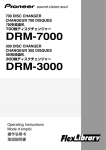
FLEXIBLE UNIT DESIGN
EASE OF INSTALLATION
The Pioneer DRM-7000/DRM-3000-disc changer is designed
so that a variety of different components may be purchased
and installed together to meet a variety of different needs.
The Pioneer DRM-7000/DRM-3000 comes with bays (i.e.,
spaces for the installation of drives or 50-disc magazines)
located at the front and rear of the unit, and the bays are
fitted with access doors that are designed to open widely
and enable you to install or remove individual components
with ease.
The front bay is for exclusive use with 50-disc magazines;
the rear bay has been designed as a multi-purpose installation
area:
In order to connect the changer to an existing data
management system or to build a new data management
system, it is necessary for the host computer to be able to
properly identify the changer and all the drives contained
therein and it is necessary to attach all the cables and specify
the settings needed for the host computer to control the
changer and drives.
The Pioneer DRM-7000/DRM-3000 is designed not only to
make it easy to install and add new drives, but also with a
wide range of features designed to make it easier to specify
host computer settings.
Loading Capacity
SECURITY FEATURES DESIGNED TO
PREVENT ERRONEOUS OR
UNAUTHORIZED OPERATIONS
Front bay
50-disc magazines only
Rear bay
Component
50-disc magazines
DRM-7000
DRM-3000
7
3
Max 16
Max 7
Max 8
Max 3
The maximum number of optional components that can be
installed differs depending on the component involved; for
details, consult the operating instructions for your option
components.
Combined Example
Data capacity emphasis
Performance emphasis
DRM-7000
Drives 2
Discs 720
Drives 16
Discs 370
DRM-3000
Drives 2
Discs 320
Drives 8
Discs 170
If desired, you can start with empty bay spaces and add
devices to them as your requirements increase.
THREE DIFFERENT TYPES OF DISC
MAGAZINES EQUIPPED WITH INTERNAL
MEMORY
In order to prevent interference, conflicts, or clashes occurring
between manual operations and computer-based operations,
entering procedure to the system administrator mode is
introduced. Anyone who wants to perform operations from
the control panel is required to enter system administrator
mode first, using the provided lock release key. And it is
possible to prevent the switchover to some sub-modes by
issuing a command from the host computer.
It is also possible to assign security privileges on the system
administrator who has the lock release key. Then operations
directly manipulating discs, like opening mailslot and ejecting
hyper magazine, are permitted to only the system
administrator.
CONTROL PANEL FITTED WITH AN LCD
MESSAGE WINDOW FOR EASE OF USE
The control panel is fitted with a 2-line, 16-column LCD
message window which is used to display instructions on
the proper operations to perform. And this makes it possible
to perform any of the wide variety of different operations
provided by the DRM-7000/DRM-3000 with only 5 keys.
Pioneer provides three different types of disc magazines
designed for convenience and ease of use in different
applications.
20-disc hyper magazine:
The main feature of the hyper magazine is its mobility. It
can be inserted and removed without opening the access
door. Another feature is a smart memory system that
records all user operations toward its lock/unlock
mechanism. One hyper magazine is provided as a standard
equipment with each Pioneer DRM-7000/DRM-3000.
50-disc magazine (locked-type):
This model is perfect for managing offline media where
the security and unchangeableness may be required. Builtin locking mechanism makes it impossible to remove discs
from magazine whenever it is outside the changer.
50-disc magazine (normal-type):
This model is convenient for importing or exporting large
volumes of discs into or from the changer. You can insert
discs into or remove them from a magazine releasing the
locking mechanism by a knob fitted with this magazine
when it is outside the changer.
5
<DRC1184>
En
English
FEATURES
HANDLING PRECAUTIONS
INSTALLATION
FOR SAFETY
Select an installation site with a flat, solid surface.
Do not install the system where it will suffer any of the
following:
1 Exposure to direct sunlight or a heater
2 High humidity or dust
3 Proximity to bathroom or kitchen
4 Exposure to spotlight
5 Proximity to any large electric apparatus such as a
refrigerator, air conditioner, dimmer, etc.
6 Uneven or unsteady installation surface.
(If the surface is not flat, first put down a hard plate or
similar support so that the system is installed level.)
7 Difficulty of service and maintenance.
÷ Do not install the unit on any unsteady platform or desk,
etc., as the unit is tall and heavy.
÷ Do not stack the units or do not place a heavy object on
the unit. It is extremely dangerous to do this, because the
objects may fall off or the unit may topple over. (Any
damage or injury suffered as a result of such installation is
the sole responsibility of the user. )
÷ Attach the placement fixtures first after unpacking the
changer. If it is moved before they are attached, there
is a danger of it toppling over or of the cables on the
rear being damaged.
÷ Always be sure not to insert your hand into the 20disc hyper magazine bay or not to touch any parts
inside of the bay when the power has been turned on,
otherwise it may result in bodily injury.
÷ The Changer can accommodate only the discs with a
diameter of 12cm (5in). As the Changer detects the
presence of disc with optical detection of the position at
about 5mm (3/16in) inside the external periphery of the
12cm (5in) disc, the use of a disc which is transparent at
the corresponding position or a 8cm (3in) disc may lead to
disc detection error and to the disc damage in the worst
case. Also, the use of a 8cm disc adapter is strictly
prohibited.
÷ For safety reasons, the DRM-7000/DRM-3000 is designed
so that the access doors cannot be opened while the
changer mechanism or internal drives are in operation.
÷ The high speed rotation of discs or the operation of the
high speed disc transport mechanism in the DRM-7000/
DRM-3000 causes slight vibrations and noise, but this does
not indicate a problem. And it does not effect the
performance of the changer.
If the changer is to be installed next to a wall, a minimum of
at least 50 cm of space must be provided between the back
of the changer and the wall.
Avoid placing objects directly on the changer.
HANDLING PRECAUTIONS
÷ Be careful not to stain, scratch or leave fingerprint, etc.,
on the signal surface, or recording surface of the discs.
The specified playback performance or recording
performance may not be obtained with such discs.
÷ Do not insert more than one disc in a mailslot, otherwise
malfunction will result.
÷ The Changer does not manage the disc contents. The data
should be managed by involving the host.
÷ Use only recording discs recommended by Pioneer. The
specified recording performance or playback performance
may not be obtained if a non-recommended disc is used.
Please note that the data recorded on discs is not covered
by our warranty.
÷ Pioneer may not be held liable for the loss of any data or
any other direct or indirect damage suffered as the result
of the use or breakdown of this product. It is strongly
recommended that regular backups be taken of all critical
data.
÷ Please be careful not to lose the lock release keys provided
with your DRM-7000/DRM-3000, otherwise you could not
manage your changer any more. The lock release key
certifies you as a system administrator and gives you a
privilege to open access doors, to eject a hyper magazine
and to use a mailslot.
POWER-CORD CAUTION
Handle the power cord by the plug. Do not pull out the plug
by tugging the cord and never touch the power cord when
your hands are wet as this could cause a short circuit or an
electric shock. Do not place the unit, a piece of furniture,
etc., on the power cord, or pinch the cord. Never make a
knot in the cord or tie it with other cords. The power cords
should be routed such that they are not likely to be stepped
on. A damaged power cord can cause a fire or give you an
electrical shock. Check the power cord once in a while. When
you find it damaged, ask your nearest PIONEER authorized
service center or your dealer for a replacement.
6
<DRC1184>
En
CONDENSATION
If the temperature difference between the changer and
environment is too large, water will condense in the changer
and the system may not provide proper performance. For
example, if you bring the changer into a warm room from
outside in cold weather, or if you increase room temperature
abruptly, condensation may result. If condensation occurs,
leave the changer for one hour in the room, or increase room
temperature gradually before using it.
CLEANING THE CHANGER
To clean the panel and the cover, use a soft, dry cloth to wipe
off dust and dirt. If the cabinet is heavily soiled, wipe off the
dirt using a soft cloth soaked with neutral detergent diluted 5
to 6 times. Then wipe the water off with a dry cloth. Do not
use benzine, thinner, insecticide or similar volatile chemicals,
as they may dissolve or discolor the cabinet surface. If you
use a chemical polishing cloth, carefully read the instructions
supplied with it.
SECURITY FEATURES
Information on the location of discs within the changer and
information to access data on discs are strictly monitored
and controlled from the changer control software and the
upper-level database management software.
Because of this, if any changes in the status of the discs
within the changer occur at a time when the changer is not
under the control of the host computer (or in a network
environment, under the control of a server), it becomes
impossible to control the changer and drives and to read
necessary files from discs.
Allowing discs stored within the changer to be removed
without any restrictions poses a security risk, not only in that
it would become impossible to access discs which have been
removed but also in that it might lead to the damage or loss
of discs.
Although the DRM-7000/DRM-3000 has been designed so
as to open the front and rear access doors from the control
panel (located at the top of the front of the unit) to remove
magazines or to insert or remove discs through the mailslots,
anyone who considers the security issues noted above will
be able to understood that it is necessary to place restrictions
on such operations.
This is why the control panel of the DRM-7000/DRM-3000
has been fitted with a key switch which may be locked to
disable operations of control keys. This switch cannot be
unlocked without the key provided with the DRM-7000/DRM3000, and if the system administrator will always keep this
key, it is impossible that ordinary users without key perform
unauthorized operations from the control panel.
It is also possible to restrict the range of operations which
are performed from the control panel. It means that a part of
system administrator’s privileges is controlled by the
command issued from the host computer and even if a
system administrator has the key, the host computer makes
it impossible to open the access doors, exchange discs, or
perform other unfavorable operations for itself.
OFFLINE MEDIA MANAGEMENT
The DRM-7000/DRM-3000 provides the following features
which makes it perfect for the management of offline media.
¶ Removable disc magazines
Disc magazines may be removed from the changer with
the discs left in the magazines. The use efficiency of the
space within the changer may much improve if the
infrequently used discs are collected in one magazine and
it is taken out from the changer into the offline storage.
All of the discs within an inserted magazine become
available immediately no matter which magazine bay it is
inserted into as long as the discs installed in the magazine
have been registered in the database as corresponding to
the magazine ID in question, and the same holds true when
a magazine is inserted into a different changer as long as
the changer in which it is inserted is under the control of
the same database.
¶ Disc magazines designed for easy tracking and control
Removing, inserting or replacing discs in magazines after
they have been removed from a changer may destroy the
correspondence between discs and magazine IDs.
To solve this problem, Pioneer provides 50-disc magazine
which has a locking mechanism to prevent all attempt to
change the status of the magazine outside the changer
and hyper magazine which has a smart memory system
that records all user operations toward its lock/unlock
mechanism so as to make it easier to track and control
the use of offline media.
¶ Registration of changer ID
When a disc magazine has been inserted into a changer
not under the control of the database management
software or into a changer belonging to another system,
the discs within that magazine may be rewritten or may
be replaced with other discs within that changer. Even if
the magazine in question is a locked-type, these
discrepancies between the discs actually contained within
the magazine and the information on those discs stored in
the database may be arise.
In order to prevent such problems from occurring, disc
magazines are designed to record the ID of the changer in
which they are used, and as long as the database has a
list of the IDs of changers controlled under the given
database, it is possible for the database management
software to determine whether or not a inserted disc
magazine has to be reinstalled by checking the changer
ID that may be read with the magazine ID.
However although the DRM-7000/DRM-3000 changer and
disc magazines do provide the features needed for the
management of offline media, it should be noted that the
actual procedures and methods available for the management
of offline media may differ depending on the database
management software and changer control software being
used.
It should further be noted that it is necessary to establish
how to employ controls for the handling of offline media. In
fact if management controls are strict enough, it is even
possible to use normal-type disc magazines which would
ordinarily be unsuited for use in the management of offline
media, in the same way as one would use locked-type disc
magazines.
¶ Unique disc magazine IDs
All disc magazines used in the DRM-7000/DRM-3000 are
assigned unique ID codes which makes it possible to
identify individual magazines simply by inserting them into
the magazine bays.
7
<DRC1184>
En
English
READ BEFORE USE
Read before use
DECIDING ON SYSTEM
CONFIGURATION
Before installing or using the changer, the first thing which
has to be done is to decide what components you should
install to where of the changer.
The connector panel and SCSI cables which come with the
DRM-7000/DRM-3000 are prepared on the assumption of the
following system configuration:
7 Two drives
7 Both drives will be connected internally with multi drive
connector panel and the provided changer/drive SCSI cable
is used to connect the drive SCSI ports to the changer
SCSI ports
(Note that it is also necessary to purchase another SCSI cable
to connect the changer to the host computer when the DRM7000/DRM-3000 is to be used in the above configuration.)
If you wish to install three or more drives or to use more than
one SCSI bus to increase data transfer speeds, it will be
necessary to purchase additional connector panels and SCSI
cables.
To determine what additional equipment must be purchased
in order to create a desired configuration, it is recommended
that you first decide where drives are to be installed and
consult the configuration sheet on p. 225 (DRM-7000) or p.
226 (DRM-3000) before actually trying to configure your
system.
Before actually beginning to configure your changer system,
it is absolutely necessary that the following items be
determined:
¶ The types and numbers of drives to be installed and where
they are to be installed. (An additional power unit is
necessary when installing 9 or more drives on the DRM7000).
¶ The positions where connector panels are to be attached.
(Note that the DRM-7000/DRM-3000 comes equipped with
a multi drive connector panel and if you need single drive
connector panels you must purchase them.)
¶ The SCSI IDs to be assigned to each of the drives to be
installed. (Note that it is impossible to assign the same
SCSI ID to two or more drives on the same SCSI bus.)
¶ The connecting plan of the cables running between
individual drives and connector panels.
¶ Which drives are to be terminated (i.e., the drive’s
termination switch of the terminal drive in each SCSI chain
is to be turned on).
By adding an optional expansion power unit to the DRM7000, power can be supplied to rear bays #9 – 16.
The maximum power consumption of these upper bays
and the maximum amount of power which may be supplied
over a single connector is the same as that of the lower
bays (i.e., Bay #1 – Bay #8).
NOTE:
¶ Be sure never to use any add-on products other than
Pioneer products.
¶ When turning off the power and turning it back on,
always be sure to allow an interval of 10 seconds or
more to elapse after turning off the power before turning
it back on. Note that this must be done because there
are times when the power is not switched off
immediately even after the power switched has been
flipped off when few drives have been installed in the
changer.
ADD-ON PRODUCTS
The following components may be purchased separately for
use with the Pioneer DRM-7000/DRM-3000 in order to adapt
it for use in configuring a system to your own specifications.
The maximum number of optional components that can be
installed differs depending on the component involved; for
details, consult the operating instructions for your option
components.
50-disc magazine
Used to store discs within the changer, these magazines
come in both normal and locked types which can be installed
in whatever combination best fits your needs.
¶ 50-disc magazine (locked-type)
[DRM-AL751]
An example of how SCSI cables should be connected is
shown on p. 19.
The power unit provided as standard equipment is capable
of supplying power to rear bays #1 – 8. The total power
consumed by these eight drives should not exceed the
following:
DC +5 V 12 A or less
DC +12 V 8 A or less
The maximum current capacity of a single connector is as
follows:
DC +5 V Max 4 A
DC +12 V Max 4 A
8
<DRC1184>
En
These disc magazines are designed so that the lock is not
released even when a magazine is removed from a
changer. Therefore the mailslot is necessary to insert discs
into these magazines or remove discs from them. These
magazines are extremely effective for use in situations
where they are used in combination with a host computer
which supports offline media management. (See p. 7 for
further details.)
Read before use
¶ 50-disc magazine (normal-type)
DVD-R/RW drive unit [DVD-R7322]
Power consumption: DC +5V, 1.5A
DC +12V, 1.0A
English
[DRM-AF751]
The DVD-R7322 internal DVD-R/RW drive unit may be used
both to read ordinary DVD-ROM discs and to read from and
write to DVD-R/RW discs.
Fitted with a knob which is used to release the locking
mechanism, these magazines are convenient for importing
or exporting large volumes of discs into or from the
changer.
DVD-ROM drive unit [DVD-D7563]
Power consumption: DC +5V, 1.0A
DC +12V, 1.0A
20-disc hyper magazine [DRM-AH721]
The DVD-D7563 internal DVD-ROM drive unit may be used
to read DVD-ROM discs.
This magazine is designed to make it possible to insert or
remove without opening the access doors. This magazine is
also equipped with a smart memory system that records all
user operations toward its lock/unlock mechanism. Therefore
the hyper magazine is convenient and also perfect for the
management of offline media. The DRM-7000/DRM-3000
comes with a hyper magazine as a standard equipment, and
additional hyper magazines may be used to easily build up an
offline library in 20-disc units.
Disc flip unit [DRM-UF701]
The DRM-UF701 disc flip unit is designed for use in turning
over a disc. Note that this component is required when using
double-sided DVD discs.
9
<DRC1184>
En
Read before use
Power supply unit [DRM-PW701] (for DRM-7000)
A DRM-PW701 add-on power supply unit must be installed
in order to use 9 or more drives within the same changer.
Always be sure to contact Pioneer service personnel for
installation.
Power supply: Maximum of DC +5V, 12A
Maximum of DC +12V, 8A
ITEMS INCLUDED
20-disc hyper magazine ... 1
Malti drive connector panel [DRM-SN721]
The DRM-SN721 multi drive connector panel comes with a
cable which may be used to connect two internal drives.
The DRM-7000/DRM-3000 comes with a DRM-SN721 panel
as a standard equipment, and this panel may be used to
connect 2 or 4 additional drives in a daisy chain.
Single drive connector panel [DRM-SN711]
Changer/drive SCSI cable ... 1
The DRM-SN711 single drive connector panel is used when
a drive is to be connected directly to a host computer or when
drives are to be daisy-chained outside of the changer unit.
Cable for 2 drives [DRM-SC721]
The DRM-SC721 2-drive SCSI cable is designed for internal
daisy-chain connection to additional two drives. When used
in combination with the DRM-SN721 multi drive connector
panel, this cable makes it possible to connect up to 4 internal
drives.
Power cord (for Canada and the U.S.) ... 1
Cable for 4 drives [DRM-SC741]
The DRM- SC741 4-drive SCSI cable is designed for internal
daisy-chain connection to additional four drives. When used
in combination with the DRM-SN721 multi drive connector
panel, this cable makes it possible to connect up to 6 internal
drives.
This type of power cord is for use
in America and Canada only.
Do not use this power cord in places
other than America or Canada.
Power cord (for Japan) ... 1
This type of power cord is for use
in Japan only.
Do not use this power cord in a
places other than Japan.
Base stabilizer
DRM-7000: 4
10
<DRC1184>
En
DRM-3000: 2
Read before use
Lock release key ... 2
Discs which may be used with the Pioneer DRM7000/DRM-3000
The types of discs which may be used with the Pioneer DRM7000/DRM-3000 vary depending on the types of drives being
used, and for further information on the types of discs which
may be used you should accordingly consult the operating
instructions provided with your drive units.
Screw for use in attaching base stabilizers
DRM-7000 ... 12
DRM-3000 ... 6
Operating instructions ... 1
Handling the discs
÷ Avoid touching the signal surface when you use a disc.
÷ To hold it, place your fingers on the edge of the disc or the
edge of the center hole and the disc edge.
÷ Do not attach paper or stickers to the label side of the
disc. Handle discs carefully and avoid damaging the label.
÷ Discs rotate at high speed in the changer. Do not use
defective discs (e.g., cracked or considerably warped).
Such discs may damage the changer.
÷ DO NOT use non-standard discs, as these may adversely
influence this unit and other equipment.
÷ DO NOT play a CD having other shape than a circular disc,
such as heart shaped disc, or malfunction may occur.
Do not use the following types of discs for they may cause
malfunction of the unit or damage to the discs:
÷ Disc which has a molding flash (projected fin) left on the
periphery as shown in the illustration.
÷ Disc with its edges are rounded or tapered as shown in
the figure.
11
<DRC1184>
En
English
DISCS
TO AVOID PROBLEMS
The following is a list of operation items that may potentially lead to problems in component functioning.
Issue
Potential Malfunction/Error
÷
Do not place foreign objects inside the changer, since malfunction
may result.
÷
[E83], [E99], [E88]
÷
Do not use the changer in locations subject to high concentrations
of dust, heat, or humidity.
* Do not install in locations directly exposed to outdoor dust or air.
* Do not install near air conditioner vents or air cleaners.
÷
Recording/playback malfunction
÷
Do not subject the recorder to impact or vibration during use.
* Do not install in hallways or other areas near frequent pedestrian
traffic.
When connecting exterior SCSI cable, be sure that power is first
turned off to host computer and changer.
* When connecting internal SCSI cable, power may be left while
connecting.
÷
Recording/playback malfunction
÷
Changer malfunction
÷
When installing a drive, be sure to connect the changer interface
cable to the connector corresponding to the bay in which the drive
is installed. If the cable is mistakenly connected to a neighboring
connector, the discs may be damaged and the E99 error may occur.
÷
[E83], [E99]
÷
Be sure to set the terminator switch to ON on the final component
connected to the SCSI bus. If it is mistakenly set to OFF, the changer
operation may be unstable. If malfunctions occur with the switch
set to OFF, set the switch to ON and turn the power on again.
* When a component's terminator switch is set to ON, if the component is subsequently removed from the SCSI bus, or if the
component's SCSI cable is disconnected, the condition immedi
ately reverts to the same state as when the terminator is OFF,
thus resulting in the same condition as above.
When installing a drive, if the wiring monitor indicator does not flash,
recheck and install the power cable connection, followed by the
changer interface connection.
÷
Display window (LCD)
doesn't appear correctly.
Operation keys malfunction.
Changer not recognized
on the SCSI.
÷
Changer does not detect
drive.
÷
Never disconnect power while the changer is transporting a disc, or
when the writer is recording data to a disc.
÷
÷
Changer malfunction.
Data recording malfunction
÷
When turning the power off and then on again, wait at least ten
seconds after turning the power off before turning it on again.
4. Control
÷
During data recording, do not send commands from the disc writer
to remove disc (Move Medium, Rezero Unit), since EC❋ error or
write malfunction may occur (back buffer underrun).
÷
÷
Recording malfunction
[EC❋], (where ❋ = 0 – F)
5. Transporting Unit
÷
When transporting the unit, pack the unit in its original packaging
materials, and ship in an upright position. Do not transport the unit
on its side.
÷
Do not transport the unit with drive units, 50-disc magazines or other
optional accessories loaded (except for 20-disc hyper-magazine).
When transporting the accessories, repack them in their original
packaging materials.
÷
Do not transport disc magazines with discs loaded.
÷
E8❋, E9❋, EF8, or EF3 errors cannot be corrected merely by resetting the changer's power on/off. The system administrator mode
must be used to open and then close the door again. For these and
other errors, see the Operating Instructions, p. 44.
÷
[E8❋], [E9❋], [EF8], [EF3]
(where ❋ = 0 – F)
1. Installation
2. Connections
÷
÷
3. Power ON/OFF
6. Error Correction
12
<DRC1184>
En
÷
÷
TO AVOID PROBLEMS
7. Discs
8. Disc Magazines
9. Disc Reversal Unit
Potential Malfunction/Error
÷
Blank discs, discs which have experienced failed recording operations, and discs whose recording sessions have not been closed,
cannot be used on the reader drive.
* Use the writer drive to determine whether a disc is blank.
÷
÷
÷
Do not affix paper labels or seals to discs. Also, do not allow the
printed surface of discs to become scratched.
* If a paper label is removed incorrectly, it may leave behind pieces
of adhesive that cause player malfunction; as a result, when re
moving an adhesive label, be sure to remove it carefully and fully,
taking care not to leave an scratches on the surface of the disc.
÷
÷
Scratches, fingerprints, or dirt adhering to the surface of a disc may
interfere with recording or playback. When handling discs, take care
not to touch the signal surface (the reflective recording surface).
Hold discs either by the outside edges, or by placing a finger in the
center hole.
÷
Recording/playback malfunction
÷
If a disc is soiled, wipe gently with a soft cloth in a radial direction,
straight from the center outwards. Do not wipe in a circular pattern.
* Use only the Pioneer Cleaning Cloth (Service Parts GED-009) for
wiping discs.
÷
Recording/playback malfunction
÷
To produce stable recording and playback, use only recommended
discs. For recommended discs, consult your dealer or Pioneer's
website.
÷
Recording/playback malfunction
÷
This component does not support DVD-R for Authoring media.
÷
Cannot record
÷
When inserting discs in magazines, be sure they are inserted flat
into the same slot; discs may be damaged if inserted diagonally (with
left and right edges in differing slots).
÷
[E83], [E99]
÷
Do not allow the open end of magazines to point downward, since
discs may fall out.
÷
[E83]
÷
Insert magazines slowly into the changer, since discs may fly fall out
if the magazine is inserted with excessive force.
* When inserting a magazine, if the electronic buzzer sounds or
error [E83 disc set NG] appears in the display, remove the magazine, press any dislodged discs back into the magazine, and slowly
insert the magazine once again.
÷
[E83]
÷
When the Pioneer Disc Flip Module DRM-UF701 is used in conjunction with the changer DRM-7000, the changer must be equipped
with firmware Rev. 1.12 or later. Since malfunctions or disc damage
may occur when used with firmware revisions earlier than 1.12, be
sure to update your firmware before use to version 1.12 or later. For
details regarding updating of firmware, consult your Pioneer service
center, or retail dealer.
* The DRM-3000 module is not limited by firmware revisions.
÷
÷
[EC❋], (where ❋ = 0 – F)
Other malfunctions
Reader drive malfunction
[Set Up NG] error
Recording/playback malfunction
÷ [E83], [E99]
13
<DRC1184>
En
English
Issue
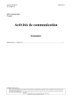
NAMES AND FUNCTIONS OF INDIVIDUAL PARTS
FRONT
FRONT ACCESS DOOR INSIDE
1
2
3
<Control panel>
5
ESC
ENT
6
FUNCTION
9
4
LOCK
UNLOCK
7
POWER
1
2
3
4
5
ROBOTICS
BUSY
DRIVE
BUSY
MAILSLOT
OCCUPIED
20-disc hyper magazine
Control panel
Mailslot
Front access door
LCD message window
The backlight to the LCD message window is designed to
automatically go into energy saving mode whenever more
than 1 minute passes without any operations being
performed from the control panel.
6 Operation keys
These keys are used to change the display items on the
LCD message window and to select setting fields or
values. Note that a lock release key is required in order to
become effective these keys.
Escape key (ESC):
The escape key is used to step back from the message
layer currently being displayed (i.e., to return to the
previous display) or to halt operations.
|«:
This key is used to decrement displayed values or to
move the display cursor down or to the left.
»\:
This key is used to increment displayed values or to
move the display cursor up or to the right.
Enter key (ENT):
The enter key is used to step forward from the message
layer currently being displayed or to initiate a specified
operation.
14
<DRC1184>
En
8
Function key (FUNCTION):
The function key must be pressed in order to enter the
system administrator mode.
7 Lock/Unlock key switch
Inserting a lock release key into this switch and rotating it
90 degrees releases the operation lock and makes it
possible to perform operations from the control panel.
8 Status indicators
POWER:
This indicator lights up whenever the power is on.
ROBOTICS BUSY:
This indicator lights up whenever a disc transport
mechanism is in operation.
DRIVE BUSY:
This indicator lights up whenever one or more discs
are being placed on each drives.
MAILSLOT OCCUPIED:
This indicator lights up whenever a disc is placed in the
closed mailslot.
9 Front bays
DRM-7000
For use with disc magazines: M1 – M7
DRM-3000
For use with disc magazines: M1 – M3
Names and functions of individual parts
REAR ACCESS DOOR INSIDE
English
REAR
2
1
9
3
4
5
TERM
OFF
ON
CHANGER
POWER
ID
SCSI
OFF
ON
AC IN
6
7
GND
8
1 Rear plates
These plates cover the space for attaching the connector
panels.
2 Rear access door
3 Drive SCSI ports (attached connector panel)
4 SCSI ID switch (ID)
This switch is used to assign the changer SCSI ID. If you
would like to decrement the displayed SCSI ID, push the
small switch just above the numeric display by a nib. And
if you would like to increment, push the small switch just
below the numeric display. Note that SCSI ID is set to ‘6’
at the time of shipment.
5 SCSI termination switch (TERM)
This switch is for SCSI termination. Note that this switch
is set ON at the time of shipment and it must be kept ON
during the changer installation. But when the SCSI bus
connection is completed and the changer is not the last
device on the SCSI bus, it must be set OFF certainly.
6 Changer SCSI ports (CHANGER SCSI)
7 Power switch (POWER)
This switch is used to turn the power to the changer on
and off.
8 Power inlet (AC IN)
The power cord is inserted into this power inlet. (Note
that you should always be sure to use only the power cord
provided with your changer.)
9 Rear bays
DRM-7000
For use with disc magazines: M8 – M15
For use with optional units/modules: Bays #1 – 16
DRM-3000
For use with disc magazines: M4 – M7
For use with optional units/modules: Bays #1 – 8
15
<DRC1184>
En
INSTALLATION
3. Lock the casters
STEP 1
1. Attach the base stabilizers.
To prevent the unit from falling over, be sure to attach the
accessory base stabilizers. The DRM-7000 is provided with
four stabilizers (one at each corner), and the DRM3000 is
provided with two (rear corners only).
Four casters at the bottom of DRM-7000/DRM-3000 allow it
to be moved lightly but they must be locked soon if you place
the changer on the chosen location. A caster is locked by
lowering its lever.
Lock
Base stabilizer
4. Connect power cord
Insert the power cord into the power inlet on the rear of the
changer and then insert the plug into a wall power outlet.
NOTES:
¶ Be sure to attach the base stabilizers before doing anything
else.
¶ Note that the base stabilizers also serve to protect the
ports and cables on the rear of the unit.
¶ Note that any damage incurred as a result of the unit falling
over or any damage caused to the rear ports or cables as
a result of a failure to install the base stabilizers will not be
covered under warranty.
¶ In the case of the DRM-3000, be sure to attach the
stabilizers only to the rear corners of the unit.
2. Deciding on the location where the changer is
to be installed
The changer is designed with a rear access door which can
be opened in inserting or removing drives or disc magazines,
and the location where the changer is to be installed should
be chosen so as to allow a minimum of 50cm of space
between the rear of the changer and the nearest wall so as
to leave enough room to open the rear access door and insert
or remove drives or disc magazines.
um
nim cm
i
M 50
of
16
<DRC1184>
En
NOTE:
Always be sure to use only the power cord supplied with
your changer.
Also be sure to follow the instructions on the label on the
package and use only that cord designed for use in the
location in which the power cord is to be used.
Installation
Readying the changer for operation
In order to ready the changer for operation, perform the
following steps in the order indicated.
1. Turning on the power (see p. 17)
2. Loosening the shipping screws (see p. 17)
3. Installing drive units (see p. 17)
4. Connecting SCSI cables (see p. 18)
5. Inserting disc magazines (see p. 20)
6. Closing access doors (see p. 23)
3. Installing drive units
No tools are required for attaching drive units. Note that while
drives may be installed in any of the rear bays from #1 – #8,
the location of the connector panel that has been attached at
the time of shipment had been designed for drives to be
installed in bays #1 and #2.
1. Attaching add-on connector panels, if necessary
Screwdriver
1. Turning on the power
When the power is first turned on, both the front and rear
access doors will automatically open. This is not a faulty
operation but the function of the shipping screws tightened
at the time of shipping or re-transporting.
NOTES:
¶ Be sure not to close neither the front nor rear access door
until all drives and disc magazines have been installed.
¶ If the door does not open when the power is turned on,
wait until the initialization routine has completed and the
LCD shows the user mode display (p. 23), then refer to p.
37 ("System Administrator Mode: Door Sub-mode") for
instructions on opening the door.
2. Loosening the shipping screws
When the front access door is opened, shipping screws may
be seen at near the bottom inside the changer. These screws
are attached to prevent damage to the built-in mechanism of
the changer during transporting.
Shipping screws are designed so that they can only be
loosened and cannot be removed so as to prevent their
2. Attaching drive units
Before installation, be sure to specify the following settings
at the rear of each drive to be installed. (See the operating
instructions provided with drive for details.)
¶ SCSI ID assignment
Specify the SCSI IDs to be used so as to ensure that the
same SCSI ID is not assigned by more than one drive on
the same SCSI bus.
¶ Termination
Set the termination switch of the last drive in the SCSI
chain to the ON position.
1 When inserting a drive, be sure to place the drive on the
changer guide rails and push the drive in until the lock
lever on the drive shifts to the locked position. Maybe you
can hear a clicking sound then.
Guide rails
Shipping screws
Drive
becoming lost.
NOTES:
¶ Be sure to tighten again the shipping screws before retransporting the changer.
¶ If you or someone close the front or the rear access door
with the shipping screws loosened, the closed door can
not open automatically like before. And when the both
doors are closed, the changer starts its mechanical
initialization. So if you have not finished the installation
yet, it is necessary to open the access doors again to
continue with installation. (See System administrator
mode: Door submodes on p. 37 for further information.)
Lock lever
17
<DRC1184>
En
English
STEP 2
Installation
2 Connect the power cable.
¶ When the power cable has been connected, the wiring
monitor indicator on the rear of the drive (orange) will
light up.
¶ When the termination switch of the drive is set to on,
the termination indicator (green) will light up.
NOTES:
¶ If installed drives are to be connected to different SCSI
buses, then the same SCSI ID assigned to each of the
drives may be all right.
¶ Even if none of the drives installed within a changer has
been assigned the same SCSI ID, it is necessary to check
that the same SCSI ID is not assigned to other devices
(e.g., hard disks) on the same SCSI bus.
Power cable
4. Connecting SCSI cables
After installing all drives and checking to make sure that they
have been properly connected, install the SCSI interface
cables.
Wiring monitor indicator
Termination indicator
3 Connect the changer interface cable.
¶ When the changer interface cable has been connected,
the wiring monitor indicators will flash at two-second
intervals.
Wiring monitor indicator
Changer interface cable
NOTE:
Connect the changer interface cable to the connector
corresponding to the bay in which the drives have been
installed. (Note that labels are affixed to connectors indicating
the corresponding bay number.) Note that it is extremely
important to do this, as connecting the changer interface cable
to a neighboring bay will result in damage to discs and the
disc transport mechanism.
3. Reading and self-checking the installed drive’s SCSI
ID by the changer
¶ If all drives have been assigned different SCSI IDs, a
buzzer will sound once.
¶ If the same SCSI ID has been assigned to two or more
drives, a buzzer will sound three times.
18
<DRC1184>
En
NOTES:
¶ Maximum usable SCSI cables length is 6 meters (including
length of wiring inside changer). If the SCSI cable has extra
unused connectors, connect the final (end) connector to
the terminating drive; the extra intermediate connectors
may be left unconnected if not required. (See page 19,
"SCSI Cable Connection Example").
¶ When installing 7 or more drives or when creating multi
SCSI buses system for 6 drives or less, additional multi
drive connector panels or single drive connector panels
will be required.
¶ When connecting the changer to a host computer, always
be sure to first turn off the power to both the changer and
the host computer. After the connections are finished, turn
on the power to the changer before turning the power to
the host computer back on.
¶ The changer SCSI termination switch is set to ON at the
time of shipment. Always make sure that the changer SCSI
termination switch is set to OFF when the changer is not
the last device in the SCSI chain.
¶ Note that the DRM-7000/DRM-3000 is unable to recognize
the existence of faulty SCSI cable connections or mistakes
in the assignment of SCSI IDs, and for this reason you
should always be sure to restart the host computer after
installation to make sure that all drive units and the changer
are properly recognized. This is the only way of confirming
that all SCSI devices are installed properly.
Installation
¶ Install 2 internal drives within the changer in a daisy-chain
configuration and connect the drives to the changer.
Total length of SCSI cables: approx. 2.1m
(Note that this does not include the length of the cable
running from the host computer to the changer.)
¶ Install 4 internal drives within the changer in a daisy-chain
configuration and connect the drives to the changer.
(Additional cable for 2 drives will be needed.)
Total length of SCSI cables: approx. 2.5m
(Note that this does not include the length of the cable
running from the host computer to the changer.)
Rear of changer
Terminator ON
Drive 4
Cable for
2 drives
Rear plate
Drive 3
Terminator ON
Drive 2
Drive 2
Connector panel
Drive 1
Drive 1
Changer board
Cable
Host
Host
Host computer
¶ Install 6 internal drives within the changer in a daisy-chain
configuration and connect the drives to the changer.
(Additional cable for 4 drives will be needed.)
Total length of SCSI cables: approx. 2.9m
(Note that this does not include the length of the cable
running from the host computer to the changer.)
¶ Connect 4 drives directly to the individual host adapters.
(Additional four single drive connector panels will be
needed and pre-attached multi drive connector panel may
be removed.)
Terminator ON
Drive 6
Drive 5
Cable for
4 drives
Single drive
connector panel
Drive 4
Drive 4
Host
Drive 3
Drive 3
Host
Drive 2
Drive 2
Host
Drive 1
Drive 1
Host
Host
Host
19
<DRC1184>
En
English
SCSI Cable Connection Example:
Installation
5. Inserting disc magazines
Any of the following methods may be used to insert discs
into the changer:
1. Insert discs into a normal-type 50-disc magazine and then
insert the magazine into the changer.
2. Insert discs into a 20-disc hyper magazine and then insert
the magazine into the changer.
3. Use the control panel to specify the slot into which a disc
is to be inserted and transport a disc to the specified slot
from the mailslot.
4. Issue some commands from the host computer to open
the mailslot and transport a disc to the specified slot from
the mailslot.
5. Issue some commands from the host computer to move
discs in the loaded hyper magazine to some slots within
the loaded 50-disc magazines.
¶ Hyper magazine is not able to be inserted or removed when
the power to the changer is turned off.
¶ Methods 3 through 5 may be used after the changer is
ready for operation. When inserting discs in these
methods, always be sure to insert empty disc magazines
first.
Also note that methods 3 through 5 are used when
inserting locked-type 50-disc magazines. (See System
administrator mode: Mailslot submode on p. 34 for further
information.)
¶ Whether or not it is possible to use methods 4 and 5
depends on the function of changer control software being
used, and you should check the manual which comes with
the software to check if it supports these methods to insert
discs.
NOTES:
¶ Insert with label facing upward.
¶ Insert discs horizontally. Otherwise it may result in
damage to the discs.
¶ Be careful not to scratch the reflective signal recording
surface.
¶ Do not turn a disc magazine upside down while the
lock is disengaged. Otherwise it may result in discs
falling out of the magazine.
4 Insert magazine into changer.
Holding the handle of the disc magazine, insert the disc
magazine into the changer following the changer guide
rails until it runs against the stopper.
And turn the handle to the left with pushing the magazine
in so that the lock pin on the left of the magazine slides
into the corresponding hole along the side of the changer.
Example: Loading magazine in front bay
Lock pin
Hole
Guide rails
1. Insert discs into a normal-type 50-disc magazine and
insert the magazine into the changer.
1 Turn the release knob to the vertical direction to unlock.
2 Insert discs.
3 Turn the release knob to the horizontal direction to lock
the discs into place.
≠
Handle
Release knob
Lock release
Label
20
<DRC1184>
En
Lock
Shown above is the insertion to the front magazine bay.
Though the insertion to the rear magazine bay is almost
same but note that the proper installation position is in the
place where it is very secluded.
To remove a disc magazine from the changer, pull the
handle towards you and pull the magazine from the
changer.
Installation
4 Insert magazine into changer.
Once the hyper magazine has been inserted partly into
the changer, it will be automatically loaded in.
English
Whenever a disc magazine is inserted into the changer,
its ID will be automatically read in and displayed on the
LCD message window within a few seconds.
A similar message will also be displayed whenever a disc
magazine has been removed.
ES
C
If both of these messages appear together in rapid
succession, it indicates that a disc magazine has not been
correctly inserted, and you should check the magazine to
make sure that it has been inserted properly again.
2. Insert discs into a 20-disc hyper magazine and insert
the magazine into the changer.
1 Turn the release knob to the vertical direction to unlock.
2 Insert discs.
3 Turn the release knob to the horizontal direction to lock
the discs into place.
EN
T
FU
NC
TIO
N
LO
CK
UN
LO
CK
PO
WER
RO
BO
BU TICS
SY
DR
IV
BU E
SY
MA
OCIL SL
CU OT
PIED
When the hyper magazine has been loaded, a unique
magazine ID will be displayed together with the record of
the locking mechanism.
≠
Note that the magazine will be automatically ejected if the
changer is unable to read the magazine ID, and that if this
happens you should try inserting the magazine again.
Release knob
Label
Lock release
Lock
NOTE:
If hyper magazine has been installed, see the instructions
given in System administrator mode: Hyper submode (p. 35)
removing the hyper magazine.
NOTES:
¶ Insert with label facing upward.
¶ Insert discs horizontally. Otherwise it may result in
damage to the discs.
¶ Be careful not to scratch the reflective signal recording
surface.
¶ Do not turn a disc magazine upside down while the
lock is disengaged. Otherwise it may result in discs
falling out of the magazine.
21
<DRC1184>
En
Installation
Serial numbers are assigned to each of the slots within the changer into which discs may be inserted. Note that these numbers are
assigned even when no disc magazine has been inserted, and that for this reason slot numbers never change even when a new
disc magazine is inserted.
DRM-7000
Disc storage location
Slot number
(Disc No.)
Disc storage location
Slot number
(Disc No.)
Hyper magazine
Hyper
Slot 20
to
Slot 1
#770
to
#751
hyp-20
to
hyp-01
Magazine bay 15
M15
Slot 50
to
Slot 1
#750
to
#701
M15-50
to
M15-01
Magazine bay 7
M7
Slot 50
to
Slot 1
#350
to
#301
M7-50
to
M7-01
Magazine bay 14
M14
Slot 50
to
Slot 1
#700
to
#651
M14-50
to
M14-01
Magazine bay 6
M6
Slot 50
to
Slot 1
#300
to
#251
M6-50
to
M6-01
Magazine bay 13
M13
Slot 50
to
Slot 1
#650
to
#601
M13-50
to
M13-01
Magazine bay 5
M5
Slot 50
to
Slot 1
#250
to
#201
M5-50
to
M5-01
Magazine bay 12
M12
Slot 50
to
Slot 1
#600
to
#551
M12-50
to
M12-01
Magazine bay 4
M4
Slot 50
to
Slot 1
#200
to
#151
M4-50
to
M4-01
Magazine bay 11
M11
Slot 50
to
Slot 1
#550
to
#501
M11-50
to
M11-01
Magazine bay 3
M3
Slot 50
to
Slot 1
#150
to
#101
M3-50
to
M3-01
Magazine bay 10
M10
Slot 50
to
Slot 1
#500
to
#451
M10-50
to
M10-01
Magazine bay 2
M2
Slot 50
to
Slot 1
#100
to
#051
M2-50
to
M2-01
Magazine bay 9
M9
Slot 50
to
Slot 1
#450
to
#401
M9-50
to
M9-01
Magazine bay 1
M1
Slot 50
to
Slot 1
#050
to
#001
M1-50
to
M1-01
Magazine bay 8
M8
Slot 50
to
Slot 1
#400
to
#351
M8-50
to
M8-01
NOTE:
Although slot numbers reach as high as ‘770’, this does not mean that as many as 770 discs may be available within the DRM-7000.
DRM-3000
Disc storage location
Slot number
(Disc No.)
Slot 20
to
Slot 1
#370
to
#351
hyp-20
to
hyp-01
Magazine bay 3
M3
Slot 50
to
Slot 1
#150
to
#101
M3-50
to
M3-01
Magazine bay 2
M2
Slot 50
to
Slot 1
#100
to
#051
Magazine bay 1
M1
Slot 50
to
Slot 1
#050
to
#001
Hyper magazine
Hyper
Disc storage location
Slot number
(Disc No.)
Slot 50
to
Slot 1
#350
to
#301
M7-50
to
M7-01
Magazine bay 6
M6
Slot 50
to
Slot 1
#300
to
#251
M6-50
to
M6-01
M2-50
to
M2-01
Magazine bay 5
M5
Slot 50
to
Slot 1
#250
to
#201
M5-50
to
M5-01
M1-50
to
M1-01
Magazine bay 4
M4
Slot 50
to
Slot 1
#200
to
#151
M4-50
to
M4-01
Magazine bay 7
M7
NOTE:
Although slot numbers reach as high as ‘370’, this does not mean that as many as 370 discs may be available within the DRM-3000.
22
<DRC1184>
En
Installation
6. Closing access doors
English
First check to make sure that all components have been
installed into place and all cables have been connected.
If this has been done, close the front and the rear access
doors, then the initialization of the changer mechanism will
begin.
When initialization has been completed, a message like that
shown below will be displayed on the LCD message window.
The first line of this message is used to indicate the status of
the disc changer mechanism, and the second line is used to
indicate the installed drive number and to indicate whether
or not a disc has been loaded into the drive in question.
Drive numbers are assigned in sequence from the lowermost
to the uppermost drive.
NOTE:
If the maximum number of drives appears on the LCD
message window is shorter than the number of drives
installed, open the rear access door and check the power
cables and the changer interface cables to all drives installed.
(See System administrator mode: Door submodes on p. 37
for information on how to open the rear access door.)
23
<DRC1184>
En
OPERATION
The Pioneer DRM-7000/DRM-3000 has two operation modes.
One is user mode performing the computer-based operations
and the other is system administrator mode mainly performing
manual operations from the control panel. By dividing the
admitted operations into these two modes, it becomes
possible to prevent interference, conflicts, or clashes
occurring between operations performed from the control
panel and commands issued by the host computer.
SYSTEM ADMINISTRATOR MODE
The privilege to perform operations from the control panel is
given to the system administrator who keeps lock release
keys. Note that the following steps must be performed in
order to switch to system administrator mode.
1. Insert lock release key into the key switch located on the
control panel and rotate 90 degrees to shift the switch to
UNLOCK position.
USER MODE
Once a changer has been finished its power on initialization
or closing doors after installation, it will enter user mode and
it will become able to be controlled by the changer control
software and database management software running on the
host computer. When a changer is running normally in user
mode, the LCD message window will display a series of the
following status messages in one-second intervals.
ESC
ENT
FUNCTION
LOCK
UNLOCK
POWER
ROBOTICS
BUSY
DRIVE
BUSY
LOCK
MAIL SLOT
OCCUPIED
UNLOCK
2. Press the FUNCTION key.
When the changer enters system administrator mode, a
message like that shown below will be displayed on the LCD
message window:
≠
≠
System administrator mode is further divided into 8 different
submodes.
Information submodes
≠
≠
•
•
When operating in user mode, the changer will operate in
accordance with commands issued by the host computer.
These submodes enable the system administrator to read a
changer’s current settings or read data stored within a
changer. Note that these submodes do not affect the
operations performed by the host computer and the system
administrator can obtain a variety of information without
interfering with the control of the changer from the host
computer.
¶ Inquiry submode (see p. 26)
¶ Config submode (see p. 26)
¶ Option submode (see p. 28)
¶ Info submode (see p. 32)
Maintenance submodes
These submodes are used to maintain discs and their status
within the changer. Sometimes these submodes may use
the disc transport mechanism. Therefore whenever the
changer enter any one of these submodes, some commands
issued by the host computer may be ignored.
¶ Mailslot submode (see p. 34)
¶ Hyper submode (see p. 35)
¶ Probe submode (see p. 36)
¶ Door submode (see p. 37)
24
<DRC1184>
En
Operation
System administrator mode settings screen are displayed in
the sequence indicated below.
English
NOTE:
The DRM-7000/DRM-3000 is designed so as to prohibit the
use of maintenance submodes from the host computer. Note
that while it is possible to enter system administrator mode
even though the use of these submodes is prohibited, only
the information submodes will be able to be used.
Press » key
Auto probing
Press « key
Press » key
Hot start
Inquiry submode
Press « key
Press « key
Press » key
Press » key
Press the ENT key
Option submode
Press « key
Press » key
Info submode
Press « key
Press » key
Mailslot submode
Press « key
Press the ENT key to select
the operation to be
performed and then press
the ENT key again
Press « key
Press » key
Press » key
Press » key
Press » key
Hyper I/E
Press « key
Probe submode
Press « key
Press « key
Press the ENT key to select
a category and then press
the ENT key again
Hyper submode
Press « key
Press » key
Auto eject
Config submode
Press « key
Press » key
Press » key
Alert buzzer
Press » key
Free message
Press « key
Press » key
Inquiry change
Press « key
Press » key
FAN NG message
Press « key
Door submode
Press « key
Pressing the ESC key when in inquiry submode will cause
the system to return from system administrator mode to user
mode.
NOTES:
¶ Do not change the setting of the Inquiry change
function. Units are preset at the factory to DRM7000 (for DRM-7000 model) and DRM-3000 (for
the DRM-3000 model).
¶ Do not change the setting of the FAN NG
message function. Units are set to factory
default of ON.
Log
Contents
Run-statistics
Swap
Remove
Add
25
<DRC1184>
En
Operation
Inquiry submode
Inquiry submode is the entry to system administrator mode
and also the exit to user mode. Here the DRM-7000/DRM3000 displays information its own. The data displayed is the
same as that obtained when the host computer issues an
SCSI INQUIRY command to the changer. Your changer’s
current SCSI ID and the firmware revision is seen here.
Pressing the ENT key at this time then the changer’s model
name and device ID (i.e., serial number) to be displayed.
Pressing the ESC key causes the display to return one level
above from the message currently being displayed.
To change the changer’s SCSI ID, use the SCSI ID switch
located at the lower left at the rear of the changer.
When the setting value of the SCSI ID switch is altered, the
display will show a message like that shown below. (Note
that the message shown here is the message which would
be displayed when the SCSI ID is changed from ‘6’ to ‘5’.)
The SCSI ID will be updated only when the power to the
changer is turned OFF and ON or the host computer resets
the SCSI bus on which the changer is.
Config submode
Config submode is the mode to browse the current status of
the magazine bays and the rear bays. It may be used to make
sure that all components currently installed in the changer
have been properly recognized by the changer.
Pressing the ENT key causes the display to switch to the
‘select bay’ screen. Press the « or » key to select either the
magazine bay or the rear bay.
Operation when the rear bay has been selected
Pressing the ENT key first displays the component loaded in
rear bay #1.
¶ The bay number to be displayed is selected by pressing
the » or « key.
Press » or « key
≠
Press » or « key
≠
Press » or « key
≠
Example of display for DRM-7000
¶ If the component that has been inserted in the bay
displayed is a drive unit, it is possible to read out the SCSI
ID, termination switch settings, and device ID of the drive
in question.
Press the ENT key when the displayed is the bay in which
a drive has been inserted, then it displays the above
information.
26
<DRC1184>
En
Operation
To confirm the type of magazine installed, press the ESC
key to return to the bay select screen, then select the
desired magazine bay.
NOTE:
Some types of stored information are in layers. Then pressing
the ENT key may cause the display to proceed to the next
layer and pressing the ESC key causes the display to return
one level above from the message currently being displayed.
Note that pressing the ESC key too many times will cause
the system to return to user mode.
Operation when the magazine bay has been selected
¶ Pressing the ENT key will cause the hyper magazine ID to
be displayed.
If a hyper magazine is not inserted, the following message
will be displayed instead.
As the rear bays are multipurpose bays, sometimes some
bays cannot be used as magazine bays because drives
have been installed instead. Then the message displayed
will be like that indicated below.
Example of display for DRM-7000
¶ When you wish to check to see what type of disc magazine
has been installed, press the ENT key.
¶ Pressing the » key while magazine bay 15 (M15) is being
displayed will cause the display to return to a hyper
magazine display.
When you wish to view drives, press the ESC key to return
to the ‘select bay’ screen and then select the rear bay.
NOTE:
Some types of stored information are in layers. Then pressing
the ENT key may cause the display to proceed to the next
layer and pressing the ESC key causes the display to return
one level above from the message currently being displayed.
Note that pressing the ESC key too many times will cause
the system to return to user mode.
¶ Pressing the » key while a hyper magazine is being
displayed will cause the magazine IDs to be displayed in
sequence beginning from magazine bay 1 (M1).
Press » key
≠
When no disc magazine has been inserted, the message
displayed will be as indicated below.
Example of display for DRM-7000
27
<DRC1184>
En
English
¶ If a disc has been transported to the drive, it is also possible
to press the ENT key to display the disc number.
Operation
Option submode
Some changer functions may be selected at user request. In
order to allow system administrators to make the most of
the features provided by changer control software and
database management software, optional functions may be
selected as needed. Note that requirements concerning
security levels or operations performed at the time of errors
may also change depending on the location in which the
changer has been installed, and that options should be
selected accordingly.
Option submode may be used to specify the following optional
functions.
1. Auto probing (Set OFF at the time of shipment)
2. Hot start (Set OFF at the time of shipment)
3. Auto eject (Set ON at the time of shipment)
4. Hyper I/E (Set ON at the time of shipment)
5. Alert buzzer (Set ON at the time of shipment)
6. Free message (Set OFF at the time of shipment)
1. Auto probing
It is possible that discs have been inserted into normal-type
50-disc magazines and hyper magazines before these
magazines are inserted into the changer. But it does not mean
that these imported discs are ready to use because the
changer and the host computer have not recognized yet which
slot holds a disc or not. Therefore the first thing to do is
examining which slot a disc is in, that is called probing.
While this probing function is usually performed by the
changer control software running on the host computer, in
cases where users wish to perform this before connecting
the changer to the host computer or in cases where the
changer control software being used does not support such
probing function, probe submode (see p. 36) may be used
instead. Using probe submode, however, may be
inconvenient since it requires that all of the disc magazines
to be checked be specified one by one.
Auto probing may be used to have the changer automatically
check all disc magazines which need to be checked to
determine whether or not discs have been inserted.
28
<DRC1184>
En
Press the ENT key
≠
Press the | key to set to ON
≠
Press the ENT key
≠
(Note that an “Auto probing is prohibited” message will
be displayed if auto probing is set to OFF.)
Note that even after switching auto probing function from
OFF to ON, auto probing will not actually be performed until
a reset is performed, a hyper magazine is inserted or the
mechanism initialization is finished after access doors are
closed.
When auto probing begins, the changer will begin to check
whether all slots of the disc magazines to be checked in
sequence to determine whether they are “empty” or “full”.
To turn auto probing temporarily off, turn the key switch to
UNLOCK position and press the ESC key.
NOTES:
¶ It takes approximately 2 minutes to check a 50-disc
magazine.
¶ Some commands from the host computer cannot be
executed while auto probing is being performed.
2. Hot start
3. Auto eject
When discs have been transported to drives and the power
to the changer is turned off and then the power to the changer
is turned back on, then the discs will be automatically returned
to their original slots. (Note that this automatic disc return
operation is not performed after a SCSI bus reset.)
For discs which are accessed frequently, however, it is
possible to use the hot start feature to make those discs
accessible immediately after power is turned on by leaving
the discs in the drives which had used them.
Hot start function is an optional function and it enables to
leave discs on the drives that had been using when the power
is turning on.
In network environments there are often times when
changers are installed near servers far from the locations in
which user terminals are located.
In environments such as these, when a user uses the changer
control software to issue a command requesting a disc within
a changer be removed through a mailslot, it is necessary for
the user to go to the location where the changer in question
has been installed in order to remove the disc, but before the
user reaches the changer the mailslot in which the disc has
been transported may already have been opened.
This may be convenient for some cases, however, unless a
system administrator resides near the changer it is as if there
were no security at all, and the same holds true of the ejection
of a hyper magazine.
This is the reason why it has been made possible to turn OFF
auto eject function. Placing restrictions on the automatic
ejection of mailslot tray and on the automatic ejection of a
hyper magazine, makes it possible to maintain a certain level
of security.
Press the ENT key
≠
Press the | key to set to ON
≠
Press the ENT key
≠
(Note that a “Hot start is prohibited” message will be
displayed if hot start function is set to OFF.)
NOTE:
Hot start function cannot be used when the changer control
software is designed so as to force discs to be returned to
their original slots.
Press the ENT key
≠
Press the \ key to set to OFF
≠
Press the ENT key
≠
(Note that a “Auto eject is activated” message will be
displayed if auto ejection function is set to ON.)
If auto eject function is set to OFF and a command is issued
from the host computer causing a disc to be carried to a
mailslot, the mailslot tray will not automatically open, and
instead a message like the following will be displayed on the
LCD message window.
29
<DRC1184>
En
English
Operation
Operation
Similarly, the hyper magazine will not be automatically ejected
even when an eject command is received from the host
computer, and instead like the following will be displayed on
the LCD message window.
Press the ENT key
≠
To press the ENT key to cause the tray of the mailslot or the
hyper magazine to be ejected, it is necessary for the key
switch to be in UNLOCK position. Since the tray of the mailslot
or the hyper magazine will not be ejected until a user with a
lock release key goes to the place where the changer in
question is installed and switches the key switch to UNLOCK
position, security is ensured during the interval between the
time a command is issued and the time the user actually
reaches the changer.
Press the \ key to set to OFF
≠
Press the ENT key
≠
4. Hyper I/E
While a hyper magazine is designed to be used as a disc
magazine capable of accommodating 20-discs at a time, since
it is also allowed to be removed without opening access doors
a hyper magazine can also be used as a high-capacity mailslot.
The subsystems which make up SCSI changers may be
divided into the following four types of elements:
1. Media transport element (i.e., robotics)
2. Storage elements (i.e., slots)
3. Import/export element (i.e., mailslot)
4. Data transfer elements (i.e., drives)
Although slots (which are provided by disc magazines) and
mailslot are usually defined as different elements, by turning
ON hyper I/E function it becomes possible to control a hyper
magazine in the same way as mailslot.
30
<DRC1184>
En
(Note that a “Hyper I/E is activated” message will be
displayed if hyper I/E function is set to ON.)
NOTE:
Since hyper magazines retain their attributes as storage
elements even when hyper I/E function is set to ON, the
changer control software may not treat a hyper magazine as
an import/export element.
However, hyper I/E function should always be set to OFF
when the changer control software being used does not
recognize the use of multiple import/export elements or when
there is a danger of erroneous operations being performed.
5. Alert buzzer
6. Free message
Control panel of the DRM-7000/DRM-3000 is equipped with
a buzzer which is designed to sound at designated times.
When discs are to be inserted or removed in accordance with
instructions from the host computer, messages will be
displayed on the LCD message window indicating the next
operation which must be performed.
¶ When the rear access door is opened and a drive is being
inserted:
Since it is difficult to monitor progress from the LCD
message window while inserting a drive from the rear
access door, the buzzer sounds to provide an indication
that operation is proceeding without problem.
¶ When the keys on the control panel are disabled:
The buzzer will sound while the FUNCTION key is being
pressed.
Note that the in these cases above the buzzer will sound
to provide a message to the operator in response to his/
her input, and for this reason these buzzer cannot be turned
off.
¶ When a problem occurs with the changer:
When a problem occurs with the changer, the buzzer will
continue to sound until the operator presses one of the
keys on the control panel.
If in this case messages on the LCD message window or
warning messages on the screen of the host computer
are sufficient, this alert buzzer may be turned OFF.
For example, when a disc is to be inserted or removed from
a mailslot (i.e., when auto eject function has been turned
OFF), the following message will be displayed.
While the messages displayed on the LCD message window
up until this point are the same whether a disc is being
inserted or removed, since all operations after the mailslot
has been opened are performed in accordance with
instructions from the host computer, the changer LCD
message window cannot display messages adequately.
By setting free message function ON, however, it becomes
possible to have the messages displayed on the LCD
message window overwritten by messages sent from the
host computer, and it becomes possible to display instructions
as the host computer wants to be done. It is also possible to
display other information such as the name of the application
controlling the changer, warning messages indicating that a
disc is being written, and other information which the host
computer possesses.
Press the ENT key
≠
Press the ENT key
≠
Press the \ key to set to OFF
≠
Press the | key to set to ON
≠
Press the ENT key
≠
Press the ENT key
≠
(Note that a “Alert buzzer is activated” message will be
displayed if the alert buzzer is set to ON.)
(Note that an “Free message is prohibited” message
will be displayed if free message function is set to OFF.)
Note that even if free message function is activated, if no
messages are received from the host computer, all messages
displayed on the LCD message window will consist of
messages from the changer itself.
31
<DRC1184>
En
English
Operation
Operation
Info submode
The DRM-7000/DRM-3000 stores data needed in order for
system administrators to perform daily maintenance in nonvolatile memories, and info submode may be used to browse
these data.
¶ Import-log
Import log is a sequential list of all disc slot numbers in
which discs have been newly inserted into the changer
when operating in mailslot submode (see p. 34).
The slot numbers displayed include the slot numbers not
only for discs which have been added but also discs which
have been replaced in mailslot submode. Note that discs
in normal-type 50-disc magazines which have been added
are displayed as a magazine unit.
If you press the ENT key at this point, the following menu
screen will appear which makes it possible to select the type
of information to be read.
Press « key
≠
Move the cursor to the type of information you need and
then press the ENT key.
Press « key
≠
Log
When you select log data browsing, it is possible to choose
either error-log or import-log data.
Example of display for DRM-7000
Move the cursor to either “Error-log” or “Import-log” and
press the ENT key to browse the corresponding log data.
¶ Error-log
The Error-log is a recorded history of operating errors
detected by the changer. Errors are numbered from the
most recent (1) up to a maximum of 32.
Moving the cursor to an error code and pressing the ENT
key causes a description of the type of error in question to
be displayed.
Press the ENT key gain to display detailed data regarding
the type of error.
Contents
Contents information of the changer may be retrieved in order
to browse the status of all slots within the changer.
Press « key
≠
Press » key
±
Example of display for DRM-7000
Press the ENT key
≠
Press the ENT key
≠
32
<DRC1184>
En
Note that the number displayed under the heading
“Uncertain” indicates the number of slots for which the
changer is still uncertain whether the slot is empty or full.
Run-statistics
The run statistics information may be retrieved to display the
amount of time or the number of times operations have been
performed.
Move the cursor to either “Work-time sum” or “Number of
moves” and press the ENT key to browse the corresponding
data.
¶ Work-time sum
“PowerOn-time” may be selected in order to display the
total amount of time the power has been turned on.
Press the ENT key
≠
¶ Number of moves
The « and » keys may be pressed to display the number
of any of the following four operations which have been
performed.
Elevation done:
This item may be selected to indicate the number of times
the elevation mechanism has been operated. Note that
this information is useful as a means of determining when
the elevation mechanism needs to be serviced or
maintained.
Load/Unload done:
This item may be selected to indicate the number of times
the loading mechanism has been operated in order to load
or unload a disc into a slot or a drive. When a disc is moved
from a slot to a drive, the number of load/unload operations
is normally counted as two. Note that this information is
useful as a means of determining when the loading
mechanism needs to be serviced or maintained.
Mailslot driven:
This item may be selected to indicate the number of times
a mailslot has been used. Note that an open-and-close
operation is counted as one time.
Hyper driven:
This item may be selected to indicate the number of times
a hyper magazine has been ejected or inserted. Note that
an eject-and-insert operation is counted as one time.
“Drive work-time” may be selected to display the total
amount of time each drive within the changer has been in
operation.
Press « key
≠
Press » key
±
Press « key
≠
Press » key
±
Press « key
≠
Press » key
±
Press the ENT key
≠
Press » key
≠
Press » key
≠
Note that the data indicating the total amount of time
displayed under “Drive work-time” is maintained
individually for each unique device ID, and that for this
reason always the correct value is displayed even if a drive
is reinserted into a different bay within the changer.
33
<DRC1184>
En
English
Operation
Operation
Mailslot submode
Mailslot submode is designed to use mailslot with the control
panel in order to exchange, eject, or add discs.
NOTE:
Although the insertion or removal of discs may normally be
performed only by the host computer in order to prevent
discrepancies from arising in the database, it is permitted for
the system administrator to use this mode to insert or remove
discs. When doing so, however, the system administrator
must make a record of the slots to which discs have been
moved and, when necessary, also perform database
maintenance. (Note that the slot numbers of slots for which
discs have been added may be read by using the import-log
in Info submode.)
If you press the ENT key at this point, the following “Swap,
Remove, or Add some discs?” selection menu will appear.
Move the cursor to the menu item to be selected and press
the ENT key to make your selection.
Swap
¶ Use the » or « keys to specify the slot number of the slot
for which you wish to exchange discs and press the ENT
key.
(Note that each time either one of the » or « keys is
pressed, the slot numbers in which discs have been
inserted and the slot numbers for which the changer is
still uncertain whether the slot is empty or full will be shown
in sequence.)
If there is a disc in the specified slot, the disc will be carried
to the mailslot, the tray will open, and the following message
will be displayed.
If there is no disc in the specified slot, the tray will open and
the following message will be displayed.
34
<DRC1184>
En
¶ Place the new disc in the tray and press the ENT key.
The tray will close, the following message will be displayed,
and the disc will be carried to the specified slot.
When the disc swapping operation has been completed, the
message displayed on the LCD message window will return
to the initial swap disc message with the next slot number
corresponding to the condition described above being
displayed.
To exit swap mode, press the ESC key.
Remove
¶ Use the » or « keys to specify the slot number of the disc
you wish to remove and press the ENT key. (Note that
discs may be removed by this mode only from slots for
which it is confirmed that a disc has been inserted, and
that the selection menu displayed will not change when
the ENT key is pressed if there is no confirmed slot in
which a disc has been inserted.)
The specified disc will be carried to the mailslot, the tray
will open, and the following message will be displayed.
¶ Remove the disc and press the ENT key to close the tray.
When the disc has been removed, the message displayed
on the LCD message window will return to the initial remove
disc message with the next slot number corresponding to
the condition described above being displayed.
To exit remove mode, press the ESC key.
Operation
¶ Use the » or « keys to specify the slot number to which
you wish to add a disc and press the ENT key. (Note that
discs may be added by this mode only to slots for which it
is confirmed that no disc has been inserted, and that the
selection menu displayed will not change when the ENT
key is pressed if there is no slot confirmed empty.)
The mailslot tray will open and the following message will
be displayed.
¶ Place the new disc in the tray and press the ENT key.
The tray will close, the following message will be displayed,
and the disc will be carried to the specified slot.
When the disc has been added, the message displayed on
the LCD message window will return to the initial add disc
message with the next slot number corresponding to the
condition described above being displayed.
To exit add mode, press the ESC key.
Hyper submode
Hyper submode is designed to eject a hyper magazine. Since
the DRM-7000/DRM-3000 is not equipped with an exclusive
key to eject a hyper magazine, you must enter this mode to
make the ENT key into the eject key.
¶ When the ENT key is pressed, the changer will check to
see if any hyper magazine discs are currently used in drives.
If there are such discs currently in drives, the following
message will be displayed.
It is the host computer possessing the authority to return
discs in drives to disc magazines. Therefore, if you wish
to eject the hyper magazine right now, you must return to
user mode first and issue a command requesting the discs
be returned from the host computer.
When all the discs have been returned to the hyper
magazine, the following message will be displayed.
¶ Pressing the ENT key will cause the following messages
to be displayed and the hyper magazine to be ejected.
NOTE:
If you cannot add a new disc in add mode, add the disc in
swap mode instead.
≠
If you wish to exit this mode without replacing the hyper
magazine, press the ESC key three times to return to user
mode.
35
<DRC1184>
En
English
Add
Operation
If you wish to replace hyper magazines, insert the new hyper
magazine. Note that the hyper magazine will be automatically
loaded once it has been partway inserted, and that you should
be careful not to add excessive force when inserting a
magazine.
When the hyper magazine has been loaded, a unique
magazine ID will be displayed together with the record of the
locking mechanism.
When there are no records of the lock ever having been
unlocked, the message displayed will be as follows.
Probe submode
It is possible that discs have been inserted into normal-type
50-disc magazines and hyper magazines before these
magazines are inserted into the changer. But it does not mean
that these imported discs are ready to use because the
changer and the host computer have not recognized yet which
slot holds a disc or not.
Probe submode is used to examine which slot a disc is in.
While this probing function is usually performed by the
changer control software running on the host computer, in
cases where users wish to perform this before connecting
the changer to the host computer or in cases where the
changer control software being used does not support such
probing function, probe submode may be used instead.
When there are records of the lock having been unlocked,
the message displayed will be as follows.
¶ If you press the ENT key at this point, the magazine bay
numbers into which magazines have been loaded will be
displayed in sequence.
Note that the magazine will be automatically ejected if the
changer is unable to read the magazine ID, and that if this
happens you should try inserting the magazine again.
¶ Press the » or « key to select a disc magazine and press
the ENT key to confirm your selection. The changer will
examine each of the slots within the disc magazine in
sequence to check whether or not a disc has been inserted.
≠
≠
≠
:
≠
When all fifty slots have been probed, a message will be
displayed asking if you wish to continue.
Select “Yes” to continue and “No” to quit and then press
the ENT key.
36
<DRC1184>
En
Operation
Note that once probe submode has been used to perform a
check on a given disc magazine, there is no need to ever
check again for the presence or absence of discs in that
magazine as long as that magazine is not removed from the
changer.
Door submode
This mode is used to open the access doors to swap 50-disc
magazines, to swap or add drives.
Note that it is necessary to make sure that all discs within
the changer have been returned to their disc magazines or
mailslot. Otherwise neither of the access doors can be
opened.
This may be done by the system administrator, who should
first check the status of the drives from the host computer
before halting service and returning all discs.
¶ When the ENT key is pressed, the changer will check to
see if any discs are currently used in drives. If there are
any discs in drives, the following message will be displayed.
If this message is displayed, press the ESC key to return
to user mode and issue a command requesting the discs
be returned from the host computer.
When it has been confirmed that there are no discs in
drives, the following message will be displayed. Move the
cursor to specify the access door(s) to be opened.
¶ Pressing the ENT key will cause the specified access
door(s) to be opened.
NOTE:
When either of the access doors is opened, the system will
automatically return to user mode. To enter a different
submode, press the FUNCTION key to re-enter system
administrator mode (see p. 24).
37
<DRC1184>
En
English
Probe submode may also be used to examine which slot of
the hyper magazine a disc is in, in the same manner as for
50-disc magazines.
Operation
ADDING DRIVE UNITS
Any drive designed for use in the DRM-7000/DRM-3000
changer can easily be added as a new drive.
The power unit provided as standard equipment is designed
to provide sufficient electrical capacity to support up to 8
drives mounted in rear bays #1 to #8. When adding additional
drives to the rear bays #9 – #16 of the model DRM-7000,
however, an optional additional power unit is required.
How to add a drive
1. Enter system administrator mode and enter door
submode to open the rear access door.
The following message will be displayed on the LCD
message window.
Warning about static electricity
2. Attach add-on connector panels, if necessary
Always be sure never to touch the contacts or ports of
any connectors when installing additional drives or any
other type of add-on equipment. Also be sure to touch a
metallic surface on the changer before beginning the
adding operations.
Screwdriver
NOTES:
¶ When disconnecting drive cables that had been connected
before to make the work easier, always be sure to
disconnect those cables in the following order (i.e., the
opposite order from that in which they are connected):
1. SCSI interface cable
2. Changer interface cable
3. Power cable
¶ If you wish to add a drive to a SCSI bus where the
termination for an existing drive has been turned on, the
termination for the new drive to be added must be turned
on and the termination for the existing drive turned off.
3. Place the drive on the changer guide rails, push the
drive in until the lock lever on the drive shifts to the
locked position. Maybe you can hear a clicking sound
then.
Guide rails
Drive
Lock lever
38
<DRC1184>
En
4. Connect the power cable.
If it is difficult to work, the SCSI interface cables of other
drives should be disconnected before continuing.
¶ When the power cable has been connected, the wiring
monitor indicator on the rear of the drive (orange) will
light up.
¶ When the termination switch of the drive is set to on,
the termination indicator (green) will light up.
Power cable
Wiring monitor indicator
NOTES:
¶ If installed drives are to be connected to different SCSI
buses, then the same SCSI ID assigned to each of the
drives may be all right.
¶ Even if none of the drives installed within a changer has
been assigned the same SCSI ID, it is necessary to check
that the same SCSI ID is not assigned to other devices
(e.g., hard disks) on the same SCSI bus.
7. Connect the SCSI interface cable.
If you have disconnected the SCSI interface cables of any
other drives in Step 4, be sure to remember to reconnect
those cables.
8. Enter system administrator mode and enter config
submode (see p. 26) to check that the changer
recognizes all the internal drives.
For example, three DVD-ROM drives and one DVD-R drive
have been added in the rear bays beginning from Bay #1
in sequence, the following messages will be displayed.
Termination indicator
5. Connect the changer interface cable.
¶ When the changer interface cable has been connected,
the wiring monitor indicator will flash at two-second
intervals.
Press » key
≠
Wiring monitor indicator
Press » key
≠
Press » key
≠
Changer interface cable
NOTE:
Connect the changer interface cable to the connector
corresponding to the bay in which the drives have been
installed. (Note that labels are affixed to connectors indicating
the corresponding bay number.) Note that it is extremely
important to do this, as connecting the changer interface cable
to a neighboring bay will result in damage to discs and the
disc transport mechanism.
Press » key
≠
6. The changer will then read the drive’s SCSI ID and
compare the drive’s settings to those of existing drives.
¶ If all drives have been assigned different SCSI IDs, a
buzzer will sound once.
¶ If the same SCSI ID has been assigned to two or more
drives, a buzzer will sound three times.
39
<DRC1184>
En
English
Operation
Operation
NOTES:
¶ If the changer interface cable has not been properly
connected, the changer will not be able to recognize the
drive at all. You should check the wiring monitor indicator
located on the back of the drive. When the cables have
been properly connected, the indicator ought to be flashing.
= If the indicator is lit, check to make sure that the changer
interface cable of the drive in question has been properly
connected.
= If the indicator is not lit, check to make sure that the
power cable of the drive in question has been properly
connected. If the cables need to be reconnected,
reconnect the power cable before reconnecting the
changer interface cable.
¶ If the drive is recognized but the model name of the drive
is not displayed in the lower half of the LCD message
window, disconnect all three cables and reconnect them
again.
Order in which cables are to be disconnected:
1. SCSI interface cable
2. Changer interface cable
3. Power cable
Order in which cables are to be reconnected:
1. Power cable
2. Changer interface cable
3. SCSI interface cable
9. To view the settings for all drives which have been
recognized, press the ENT key to proceed to the next
layer in the message display.
¶ The SCSI ID, termination switch setting, and unique
device ID of each drive will be read in and displayed at
the same time on the same message window.
¶ If four drives have been connected in a daisy chain
configuration and termination has been turned on for
the fourth drive in the chain, the messages displayed
will be as indicated below.
Press the ENT key
≠
Press the ESC key to return to the previous message
and then press the » key
≠
Press the ENT key
≠
40
<DRC1184>
En
Press the ESC key to return to the previous message
and then press the » key
≠
Press the ENT key
≠
Press the ESC key to return to the previous message
and then press the » key
≠
Press the ENT key
≠
NOTES:
¶ If the SCSI IDs or termination switch settings displayed
differ from those which set on the backs of drives, or if a
drive’s device ID fails to be displayed, it is likely that the
corresponding cables were improperly connected. If this
happens, follow the steps outlined below to properly
reconnect all the cables.
Order in which cables are to be disconnected:
1. SCSI interface cable
2. Changer interface cable
3. Power cable
Order in which cables are to be reconnected:
1. Power cable
2. Changer interface cable
3. SCSI interface cable
¶ If the device ID of a drive cannot be read, then it will be
impossible for the host computer to perform automatic
configuration.
10.Press the ESC key several times to return to user mode
and close the rear access door.
Press the ESC key
≠
Operation
Press the ESC key
≠
Drives may be exchanged following the same procedure as
that describing above for adding new drives.
Described below is the procedure to be following when
exchanging drives, and it also eliminates the worry of making
mistakes in the drive bay number which is to be exchanging.
Press the ESC key
≠
NOTE:
Unless there is some special reason, the SCSI ID and
termination switch settings of the drive to be installed to
replace should be the same as those of the drive to be
replaced.
Press the ESC key
≠
How to exchange a drive
1. Enter system administrator mode and enter door
submode to open the rear access door.
The following message will be displayed on the LCD
message window.
Press the ESC key
≠
2. Enter system administrator mode again and enter
config submode to select the rear bay.
Close the rear access door
≠
Press the ENT key
≠
Initialization complete
≠
Select “Rear” and press the ENT key
≠
As the remaining steps which must be performed may differ
depending on the changer control software being used, please
consult the manual for the changer control software being
used for further instructions.
Also note that it may be necessary to restart the host
computer before it can recognize the drives which have been
added.
3. Use the » or « key to select the bay in which the drive
to be replaced is currently inserted.
Note that the messages actually displayed may lack some
of the following information if the drive being replaced has
been out of order.
41
<DRC1184>
En
English
EXCHANGING DRIVE UNITS
Operation
4. Make sure the wiring monitor indicator (orange). It is
located on the back of the drive and ought to be
flashing at half-second intervals if the drive has been
selected in Step 3. Then disconnect the cables to the
drive.
Order in which cables are to be disconnected:
1. SCSI interface cable
2. Changer interface cable
3. Power cable
9. Compare the SCSI ID and termination settings of the
newly installed drive against those of the removed
drive.
¶ If the SCSI ID of the new drive is the same as that of
the drive which has just been removed, the buzzer will
sound once.
¶ If the SCSI ID of the new drive is not the same as that
of the drive which has just been removed, the buzzer
will sound three times.
5. Remove the drive.
If it is difficult to work, the SCSI interface cables of other
drives should be disconnected before continuing.
10. Connect the SCSI interface cable.
If you have disconnected the SCSI interface cables of any
other drives in Step 5, be sure to remember to reconnect
those cables.
6. Check the SCSI ID and termination switch settings of
the drive which has just been removed, and set the
SCSI ID and termination switch settings of the drive
which is to be inserted in its place to the same settings.
11. Check the drive device ID displayed on the LCD
message window.
7. Insert the new drive and connect the power cable.
¶ When the power cable has been connected, the wiring
monitor indicator on the rear of the drive (orange) will
light up.
¶ When the termination switch of the drive is set to on,
the termination indicator (green) will light up.
Press the ENT key
≠
Power cable
Wiring monitor indicator
Termination indicator
8. Connect the changer interface cable.
¶ When the changer interface cable has been connected,
the wiring monitor indicator will begin flashing at halfsecond intervals.
Wiring monitor indicator
Changer interface cable
42
<DRC1184>
En
NOTES:
¶ If the SCSI ID and termination switch settings displayed
differ from those which set on the back of the drive, or if a
drive’s device ID fails to be displayed, it is likely that the
corresponding cables were improperly connected. If this
happens, follow the steps outlined below to properly
reconnect all the cables.
Order in which cables are to be disconnected:
1. SCSI interface cable
2. Changer interface cable
3. Power cable
Order in which cables are to be reconnected:
1. Power cable
2. Changer interface cable
3. SCSI interface cable
¶ If the device ID of a drive cannot be read, then it will be
impossible for the host computer to perform automatic
configuration.
12. Press the ESC key several times to return to user mode
and close the rear access door.
Press the ESC key
≠
NOTE:
If you will replace drives without using the procedure
described above, you must be more careful not to remove
the wrong drive. In such a case, the installation procedure of
the drive is the same as that described in “How to add a
drive” (on p. 38), and note that the conditions under which
the buzzer is sounded differ slightly.
Press the ESC key
≠
Press the ESC key
≠
Press the ESC key
≠
Press the ESC key
≠
Close the rear access door
≠
Initialization complete
≠
As the remaining steps which must be performed may differ
depending on the changer control software being used, please
consult the manual for the changer control software being
used for further instructions.
43
<DRC1184>
En
English
Operation
OTHERS
TROUBLESHOOTING
Here are some tips for solving common problems that may be encountered. Some defects with discs or lack of experience in
performing operations may result in errors being displayed or in problems which seem breakdowns. Simple mistakes or
misconceptions can be corrected or cleared away by using the following table which has been provided for troubleshooting of the
system administrator.
If you still find it impossible to correct a problem or if an error message refuses to go away even after consulting the list below and
taking the recommended action, contact your service representative or the dealer from which you purchased the product for
assistance.
Also consult the section "TO AVOID PROBLEMS" on p.12.
Description of problem
Message display
Possible cause
Recommended action
Buzzer sounds when access door is
open and you insert a magazine.
M**
Disc Not Correct
One or more discs has not been
properly placed in the slots of
that magazine.
Remove the magazine and check to see
if any discs are protruding.
Buzzer sounds when you insert a
hyper magazine.
Hyper magazine
Disc Not Correct
One or more discs has not been
properly placed in the slots of
that hyper magazine.
Remove the hyper magazine and check
to see if any discs are protruding.
Buzzer sounds when power is first
turned on and initialization begins.
E83
Disc Not Correct
¶ Some foreign object has been
detected within the changer.
¶ Some discs are protruding
from their magazines.
Open the access door and check to see
if there is anything seems to be blocking
the optical sensor. If you find it then
remove it. Buzzer may stop.
Buzzer sounds and system refuses
to enter system administrator mode
when you press the FUNCTION key.
The key switch is set to the
locked position.
Use the lock release key to turn the key
switch to UNLOCK position.
Unable to enter Mailslot or Door
submode even though it is possible
to enter Inquiry or Config submode.
¶ The robotics were busy at the
time you pressed a key.
¶ Switchover to these
maintenance submodes has
been prohibited from the host
computer.
¶ Try again after making sure the
ROBOTICS BUSY indicator is off.
¶ Check to see if those operations has
been prohibited from the host
computer.
In Mailslot submode; Swap or Add,
tray opens again soon after it was
closed.
Place a new disc
& Press ENT-key
Mailslot was closed without
placing a disc on the tray.
Press the ESC key to halt the swap disc
or add disc operation.
In Mailslot submode; Remove, tray
opens again soon after it was
closed.
Remove the disc
& Press ENT-key
Mailslot was closed without
removing the disc from the tray.
Remove the disc from the tray.
As the discs in drives are not
returned even after the power is
turned off and back on, it is
impossible to open access doors in
Door submode.
The hot start function has been
turned on.
Turn hot start function off and turn the
power off and then back on. When the
discs have been returned, re-enter Door
submode and open the access door.
Access door refuses to open after
trying to open it in Door submode.
The access door is blocked and
is unable to open.
Remove whatever is blocking the
access door and try to open the access
door again.
There are some discs remaining
in drives.
Return to user mode, issue REZERO
command from the host computer
requesting that all discs be returned,
and try to perform the operation again
after all discs have been returned.
Access door selection screen fails to
appear when trying to open access
door in Door submode.
44
<DRC1184>
En
Host must return
every disc first
Description of problem
Hyper magazine cannot be ejected
in Hyper submode.
Message display
Host must return
all hyper’s disc
There exists a drive or drives which
fail to be recognized by the host
computer even though they have
been recognized in Config submode.
Possible cause
Return to user mode, issue REZERO
command from the host computer
requesting that all discs be returned,
and try to perform the operation again
after all discs have been returned.
¶ SCSI cable has not been
connected properly.
¶ SCSI ID or termination
settings have not been
correctly specified.
¶ Make sure that the SCSI cables have
been connected properly.
¶ Check to see if there is any device on
the same bus with the same SCSI ID
and to see that the SCSI chain has
been properly terminated.
¶ Re-configure the SCSI chain so that
the total length of all the cables does
not exceed the maximum allowable
length.
¶ Reboot the host computer.
¶ Operator has forgotten to
reboot the host computer.
scsiID=7 TermOFF
dev-ID=
Unable to properly read a disc which
has been inserted in a drive.
An error code is displayed on the
LCD message window and the
backlight flashes and the buzzer is
sounded.
E88, E89,E99, etc.
The LCD message window does not
come on when the power is turned
on.
Pressing the operation keys has no
effect.
Buzzer sounds when magazine is
loaded.
¶ Memory Failure
¶ Error
Recommended action
There are some discs that from
the hyper magazine remaining in
drives.
¶ The total length of the SCSI
cables is too long.
There exists a drive which fails to be
recognized by the host computer,
and the SCSI ID of the drive is set to
‘7’ when checked in Config
submode.
English
Others
¶ The power cable for the drive
in question has not been
connected.
¶ Drives have been inserted in
rear bays #9 through #16
without additional power
supply unit.
¶ Open the rear access door and check
to see if the power cable has been
properly connected.
¶ The power supplied by the power
supply included as standard
equipment is sufficient only for
operating drives in bays #1 through
#8. Reinstall the drive in one of these
bays or install the additional power
supply unit.
¶ The disc has been inserted
upside down.
¶ The disc is soiled or
scratched.
¶ Check to see if the disc has been
inserted upside down.
¶ Check to see if the disc is soiled or
scratched, and wipe away any soil or
replace the disc.
A mechanical error has occurred
which has made the changer
unable to continue in operation.
In system administrator mode, open the
access door and take whatever action is
required in order to eliminate the error
condition.
The changer SCSI termination
switch is set to OFF or the SCSI
cable is not properly connected.
¶ When installing is not finished, turn
the SCSI termination switch to ON
and turn the power OFF and ON.
¶ If the SCSI cable is not properly
connected, turn off the power. And
after connection the cable properly,
turn on the power again.
Magazine's memory data is not
being read correctly.
¶ Remove and reinsert magazine.
¶ If the magazine data still can't be read
properly, perform a "PROBE" of the
magazine, ten open and close the
door.
45
<DRC1184>
En
Others
SPECIFICATIONS
DRM-7000
DRM-3000
Description
700-disc changer
300-disc changer
Power supply
Power consumption
AC 100 V – 240 V, 50/60 Hz
Maximum of 5.5 A (500 W)
+
Maximum of 3.3 A (300 W)
General specifications
Weight of main unit (including placement fixtures) 91.7 kg (202 lb 3 oz)
External dimensions (including placement fixtures) 760 x 795 x 1520 mm (W x D x H)
Operating requirements*
60.6 kg (133 lb 10 oz)
760 x 729 x 872 mm (W x D x H)
29-15/16 x 31-5/16 x 59-7/8 in (W x D x H) 29-15/16 x 28-11/16 x 34-5/16 in (W x D x H)
+5 °C to +35 °C (+41°F to +95°F)
+
Humidity*
5% to 85% (with no condensation)
+
Storage requirements
–40 °C to +60 °C (–40°F to +140°F)
+
* The figures for permissible operating temperature and humidity may change depending on the components loaded. For details,
consult the operating instructions for each component used.
Functional specifications
Maximum number of discs
Maximum number of disc magazines
720 (12-cm discs)
320 (12-cm discs)
14
1
6
+
16
8
20-disc hyper magazine
Changer/drive SCSI cable
1
1
+
+
Power cord (for use in Canada and USA)
Power cord (for use in Japan)
1
1
+
+
50-disc magazines
20-disc hyper magazine
Maximum number of components
Items included
Base stabilizer
4
Screw for use in attaching Base stabilizer 12
2
6
Lock release key
Operations Instructions
+
+
2
1
¶ The external design of this product or any of the above specifications may be changed at any time without prior notification.
46
<DRC1184>
En
SCSI connector specifications
+
1
±
¡
English
Others
1) Pin layout of SCSI connectors
Signal name
GROUND
GROUND
GROUND
GROUND
GROUND
GROUND
GROUND
GROUND
GROUND
GROUND
GROUND
NC
NC
NC
GROUND
GROUND
GROUND
GROUND
GROUND
GROUND
GROUND
GROUND
GROUND
GROUND
GROUND
Pin No.
1
2
3
4
5
6
7
8
9
10
11
12
13
14
15
16
17
18
19
20
21
22
23
24
25
Signal name
26
27
28
29
30
31
32
33
34
35
36
37
38
39
40
41
42
43
44
45
46
47
48
49
50
-DB(0)
-DB(1)
-DB(2)
-DB(3)
-DB(4)
-DB(5)
-DB(6)
-DB(7)
-DB(P)
GROUND
GROUND
NC
TERMPWR
NC
GROUND
-ATN
GROUND
-BSY
-ACK
-RST
-MSG
-SEL
-C/D
-REQ
-I/O
NOTES:
¶ Pin No. 12 to 14, 37 and 39 are not grounded.
¶ The connectors are of the shielded type.
¶ For details on the control commands, refer to the separate
specifications manual.
2) Electrical specifications of SCSI
Output
characteristics
The signals driven by SCSI equipment
present the following output characteristics.
True (LOW): VOL = 0.0 to 0.4 V DC
IOL = 48 mA (0.5 V DC) max.
False (HIGH): VOH = 2.5 to 5.25 V DC
Input
characteristics
The signals driven by SCSI equipment present
the following input characteristics.
True (LOW): VOL = 0.0 to 0.4 V DC
IOL = -0.4 mA (0.4 V DC) max.
False (HIGH): VOH = 2.0 to 5.25 V DC
NOTES:
¶ As the SCSI interface is of the single-ended type, it should
be terminated on both ends of the cable.
¶ The maximum recommended length of an SCSI cable is 6
meters (20 feet) (including internal wiring).
Maintenance
In order to ensure safe and proper functioning of this unit,
we recommend regular maintenance. Extended service
life can be expected if maintained properly.
Published by Pioneer Corporation.
Copyright © 2002 Pioneer Corporation.
All rights reserved.
47
<DRC1184>
En