1
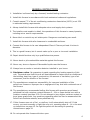
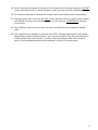
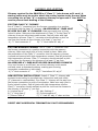
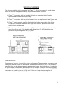
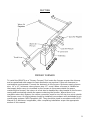
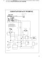
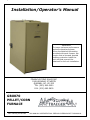
1
Installation/Operator’s Manual
Installation
To insure optimum performance
and safe operations please
follow the detailed information
provided with each furnace. We
require that a licensed, bonded
heating contractor install the
unit and that a permit be
obtained for the unit installation.
PINNACLE STOVE SALES INC.
1089 HIGHWAY 97 NORTH
QUESNEL, BC. V2J 2Y3
TEL. (250) 992-5050
FAX. (250) 992-5850
GBU070
PELLET/CORN
FURNACE
1
Rev: February, 02-20-2006
THIS MANUAL SUPERCEDES ALL PREVIOUS VERSIONS OF THIS MANUAL
TABLE OF CONTENTS
FURNACE SPECIFICATIONS
pg 2
CONTROL AND COMPONENT FUNCTIONS
pg 3
GENERAL INSTRUCTIONS
pg 4-5
CLEARANCE TO COMBUSTIBLES (diagram)
pg 6
CHIMNEY AND VENTING
pg 7
VERTICAL CHIMNEYS
pg 8
DUCTING – PRIMARY FURNACE
pg 9
ELECTRICAL REQUIREMENTS
pg 10
THERMOSTAT INSTALLATION
pg 10
TURNING OFF THE UNIT
pg 11
MAINTENANCE
pg 11
BURNING CORN
pg 12
WIRING DIAGRAM
pg 13
START UP INSTRUCTIONS PELLET
pg 14
START UP INSTRUCTIONS CORN
pg 15
PRIMARY CONTROL SEQUENCE OF OPERATION OII 350S
pg 16
TROUBLE SHOOTING
pg 17-26
PARTS LIST
pg 27
WARRANTY
pg 28
1
FURNACE SPECIFICATIONS
HEIGHT--------------------------------------------------- 45 ¼
WIDTH---------------------------------------------------- 24 ¼
DEPTH---------------------------------------------------- 33 ½
WEIGHT-------------------------------------------------- 385 lbs
VOLTS---------------------------------------------------- 110 V
FLUE SIZE------------------------------------------------ 4” Pellet Vent
BREACH--------------------------------------------------- Rear
HOPPER CAPACITY--------------------------------------- 80 lbs
BTU – INPUT--------------------------------------------- 70,000 BTU/HR
OVERALL UNIT EFFICIENCY----------------------------- 80%
WARM AIR OUTLET SIZE-------------------------------- 12” X 12”
BLOWER-------------------------------------------------- ¼ hp, 1250 CFM
COLD AIR RETURN/FILTER SIZE------------------------ 15” X 24”
2
CONTROL AND COMPONENT FUNCTIONS
AUGER The auger transfers the pellet fuel from the hopper end of the burner tube down
and into the fire pot.
AUGER MOTOR
The auger drive motor turns the auger.
BURNER TUBE The burner tube contains two passageways, one for the auger tube and the
other for combustion air. This tube supplies both the fuel and combustion air to the fire pot.
BLOWER The blower forces return air over the furnace heat exchanger and into the home’s
duct system. The blower is controlled by the fan limit control.
CUP MOTOR The cup drive motor turns the cup which dispenses fuel from the pellet hopper
to the auger.
DRAFT INDUCER The draft inducer takes combustion air, forces it down the burner tube
and into the fire pot where combustion occurs. The flame can be adjusted by regulating
the damper on the draft inducer.
FAN LIMIT CONTROL
The fan limit control automatically activates the blower on
temperature rise, and disengages on temperature fall. Normally, this control is set to bring
the blower on at 140°F and then turn off at 100°F. The fan limit control also features a
200°F limit, where if the temperature for whatever reason may climb to 200°F this control
cuts power to burner, but keeps the blower running to cool the heat exchanger. NOTE: IF
YOU ARE REPLACING THE FAN LIMIT CONTROL, MAKE SURE THE BRASS
CONNECTOR IN THE MIDDLE IS SNIPPED OR REMOVED, IF IT IS NOT IT WILL RUN
CONTINUOUSLY.
FIREPOT The fire pot is where combustion occurs. Pellets are delivered into the fire pot by
the auger. The heat of the fire in the fire pot causes gases to oxidize off the pellets, and as
the combustion air mixes with these gases, they burn with a flame similar to that of an oil
or gas fire.
HOPPER The hopper is where the pellets are stored and then funnelled down to feed the
cup.
SAFETY DISC The safety disc interacts with the burner for positive flame protection to
guard against misfires and to shut down the burner in the event of the fuel hopper running
dry. If the burner loses its flame potential, misfires, or runs out of fuel, the safety disc will
drop out, locking out the burner.
BURNER LIMIT If the unit should ever burn back into the burner tube, the 200°F limit will
open the circuit, shutting the entire burner down. The burner will not start until it is
manually reset. If this should happen, locate the cause before resetting limit and relighting
unit.
3
GENERAL INSTRUCTIONS
1. Installation is allowed only by a licensed, bonded heating contractor.
2. Install this furnace in accordance with local mechanical codes and regulations.
3. Consult manual “J” of the air conditioning contractors Association (ACCA) or air 230
to estimate heating requirements.
4. Always install this furnace with adequate return and supply duct systems.
5. The installer must explain in detail, the operations of this furnace to owner/operator,
including minor service requirements.
6. Never block or restrict any air intake ports. Dangerous overheating can result.
7. Install this furnace with safe clearances to combustible surfaces.
8. Connect this furnace to its own independent Class L Chimney at least 4 inches in
diameter.
9. This is a good furnace, but it cannot make up for a poor or incorrect installation.
10. Repair should be done only by a qualified service person.
11. Never stack or pile combustible materials against the furnace.
12. Never use, store or dispose of flammable liquids near the furnace.
13. Always have a smoke or ionization detector installed in your home.
14. Disclaimer notice: No guarantee is made regarding the heating capacity of this
unit. The actual area that this unit will heat depends on factors such as conditions of
the building, heat loss, type of construction, the amount of insulation, type of air
movement, and the location of the furnace.
15. The manufacturer accepts no responsibility for improper installation of this
pellet/corn furnace or improper use or negligence of any kind with continued use of
the furnace.
16. The manufacturer recommends fuelling this furnace with premium wood based
pelletized fuel with moisture content between 2 – 8% or clean-shelled corn with a
moisture content less than 15%. Do not attempt to burn higher moisture content or
burn lesser grade fuels. Any questions regarding pellet fuel can be answered at the
Pellet Fuels Institute website, www.pelletheat.org.
17. If this furnace runs out of fuel, or misfires, it will automatically shut-off. If this
occurs, you must manually re-light the corn unit, repeating steps 8 – 14 in the start
up instructions on page 15. Re-light the pellet unit according to operating
instructions on page 14.
18. Do not operate this furnace with door open.
4
19. Doors and heat exchanger surfaces of the furnace are hot during operation. DO NOT
touch with bare hands, or allow children to play near the furnace unattended.
20. Do not allow anyone to operate the furnace that is not familiar with its operation.
21. Manually place fuel in the fire pot ONLY when starting a fire in a cold furnace. Never
add pellets by hand to a smouldering fire or a hot fire pot. DANGEROUS smoking
could result.
22. After lighting, make sure the main fire door and ash door are closed and sealed
tight.
23. Set combustion air damper at not less than 50%. Damper settings will vary widely
depending on draft characteristics of your chimney system. The unit should emit no
visible smoke from the exhaust, if it does, open the damper slide until smoke is
gone. Draft characteristics should be between .04 and .08 inches water.
5
CLEARANCE TO COMBUSTIBLES
6
CHIMNEY AND VENTING
Chimney required for the GBU070 is 4” Class “L” (also known as PL vent). A
starting collar must be used to attach the venting system to the furnace. When
connecting into a Class “A” or masonry chimney an approved 4” liner MUST be
used to prevent back drafting of the chimney.
EXISTING CLASS “A” CHIMNEY:
Run 4” Class “L” connector from the furnace connection to a positive
connection with the class “A” chimney. AN APPROVED 4” LINER MUST
BE USED IN CLASS “A” CHIMNEYS. Make sure each joint is firmly
locked in place. Make sure the attachment of Class “L” to the Class “A”
chimney is secure with sheet metal screws. Seal all joints with high
temperature silicone. Class “L” connector should maintain a pitch on
rise from the furnace to the chimney of at least ¼” per foot.
A): “L” Vent connector 4”
B): “L” Vent elbow 90° adj. 4”
EXISTING MASONRY CHIMNEY: Run 4” Class “L” connector from
the furnace connection to a positive connection with the masonry
chimney. Make sure each joint is firmly locked in place. Make sure
the penetration of the Class “L” connector into the masonry chimney
is sound and secured with high temperature cement. Seal all joints with
high temperature silicone. Class “L” connector should maintain a pitch
on rise from the furnace to the chimney of at least ¼” per foot.
AN APPROVED 4” LINER MUST BE USED IN MASONRY CHIMNEYS.
Your new furnace is so efficient; an unlined chimney could remain
cold and cause a downward pressure creating poor burning,
incomplete combustion or back draft.
A.)“L” Vent connector 4”
B.)“L” Vent elbow 90° adj. 4”
__________________________________________________________________________
NEW VERTICAL INSTALLATIONS: Install 4” Class “L” chimney add
accessories according to manufacturers instructions and local codes
(3” clearance to combustibles). Run Class “L” chimney all the way from
the furnace connection to point of termination. Make sure each joint is
firmly locked in place. Seal all joints with high temperature silicone.
Class “L” connector should maintain a pitch on rise from the furnace to
the chimney of at least ¼” per foot.
A.) Vertical top 4”
D.) Adj. flashing 4”
B.) “L” Vent pipe 4”
E.) Fire stop spacer 4”
C.) Storm Collar 4”
F.) “L” Vent 90° adj. 4” clean out tee
DIRECT VENT HORIZONTAL TERMINATION IS NOT RECOMMENDED
7
VERTICAL CHIMNEY’S
The chimney that this unit is connected to (Class “L”, all fuel or masonry) should extend
above the roofline of adjacent buildings to prevent downdraft situations.
1. Class “L” connectors shall be installed without any downward pitch from the
appliances and without any dips or sags.
2. Class “L” connectors shall be pitched upward from the appliance at least ¼” per foot.
3. Class “L” starter adapter shall be firmly attached to the vent outlet collar of the
furnace and a positive seal made with high temp silicone, approved metal tape
and/or sheet metal screws.
4. The chimney shall extend at least three (3) feet above the highest point when they
pass through the roof of the building and at least two (2) feet higher than any
portion of any building within ten (10) feet.
HIGH BUILDING OR
SECTION OF BUILDING
COMBUSTION AIR:
Furnaces must have air (oxygen) for proper performance. The incomplete combustion that
takes place when a furnace is “air starved” causes carbon monoxide (CO) to be formed in
quantities that can be dangerous inside a well-sealed house. Having a source of combustion
air from outside prevents this “air starvation” of the furnace. Provisions for combustion air
shall be made in accordance with applicable provisions of local building codes. The GBU070
combustion air intake is the slot on the back of the unit. Keep this opening free of
obstructions which would restrict airflow.
8
DUCTING
PRIMARY FURNACE
To install the GBU070 as a “Primary Furnace” first locate the furnace as near the chimney
and as centralized with respect to heat distribution as practical. Follow all clearance to
combustible requirements. Connect the ductwork to the furnace. Minimum supply plenum
size: 14” x 14”, minimum return plenum size: 12” round. When a furnace is installed so
that supply ducts carry air circulated by the furnace to the areas outside the space
containing the furnace, the return air must also be handled by a duct sealed to the furnace
casing and terminating outside the space containing the furnace. Where there is no
complete return duct system, the return connection must be run full size to a point outside
the furnace room. Air duct systems should be installed in accordance with standards for air
conditioning systems. NFPA Pamphlet #90. They should be sized in accordance with ACCA
Manual D or whichever is applicable, after completing installation as per the appropriate
section of this manual.
9
ELECTRICAL REQUIREMENTS
1. Make sure that the power source conforms to the requirements of the furnace.
Disconnect the power source before performing any maintenance or electrical work.
2. Connect the electrical power according to the appropriate wiring diagram on the
following page.
3.
Plug the power supply into a surge protected and grounded 15-amp branch circuit.
The outlet must have the correct polarity. With a voltage tester, check the outlet
and make sure you have a minimum 115 volts and that the branch circuit is not over
loaded with too many appliances. A surge protector must be used to have electrical
items warranted.
THERMOSTAT INSTALLATION
THERMOSTAT IS SUPPLIED WITH UNIT
1. Install the thermostat in a central location. A low voltage 2-wire thermostat should
be used and installed according to manufacturers directions supplied with the
thermostat.
2. Run the thermostat wire (18/2 wire).
3. For best operation, mount the thermostat on a draft-free inside wall, if it must be
installed on an exterior wall; insulate the backside of the mounting plate.
4. See wiring diagrams for thermostat terminal locations. Leads for thermostat wire
connection off the primary control are yellow.
5. A programmable thermostat may be used but must be a 2-wire, low voltage type as
only 9 volts is switched, by the yellow wires on the primary control.
10
TURNING OFF THE UNIT
Turn the power switch to draft fan. Fuel will stop feeding but the draft fan will remain
running. Let run until fire burns out completely. Set power switch to off.
NOTE: Approximately 10 – 12 minutes should be enough time for fire to burn out. Time will
vary depending on fuel type.
MAINTENANCE
1. Check the ash pan regularly and empty as necessary. Dispose of the ashes in a metal
container, and when cooled, bury them to prevent any spontaneous fires.
2. Check the fire pot regularly for any residue build-up. Clean and dispose of them when
completely cooled.
3. Remove the two heat exchanger access panels twice per burning season and check the
heat exchanger for ash. Vacuum if necessary. Replace gasket material if any tearing or
deterioration occurs.
4. Annually check the blowers for lint deposits from carpeting, dryer lint, furniture
coverings, pet hair, etc.
5. Inspect the flue pipe or vent assembly and chimney each time the heat exchanger is
serviced (minimum twice per heating season). Clean these passages as needed. Higher
usage of the unit could require more frequent cleanings.
6.
Your unit is equipped with an aluminium air filter, wash and clean it regularly. At least
once a month.
11
BURNING CORN IN THE GBU070
NOTE: If your 070 was purchased as a corn unit the corn pot should already be installed.
The corn pot utilizes a lift out cast iron inner liner that removes for easy cleaning. A rod will
also be provided to lift the pot out of the furnace.
1.
Your GBU070 will burn most types of clean-shelled corn. It is not necessary to mix
corn with wood pellets although some people have had better success burning a
50/50 mix.
2.
Typically, burning corn requires a bit more combustion air than wood pellets. The
shutter on the draft inducer should be initially set at 50% open, the cycle time at 8
minutes and the pilot draft switch on the primary control at medium.
3.
We don’t recommend direct venting when corn is the primary fuel. For corn burning,
the GBU070 needs a natural draft and this can only come from a vertical chimney.
We do recommend stainless chimney be used when corn is the fuel. Corn, by nature,
is more acidic than pellets and can eat away steel or galvanized chimney.
4.
The moisture content of the corn should be 15% or less, and care should be taken to
ensure that there are no foreign objects in the corn (i.e.: sticks, stalks, cob pieces)
which will jam the feed system.
5.
We recommend starting a corn fire with wood pellets as corn has a
dense shell that can be difficult to start. Place 1” of coarse oyster shell in the bottom
of the pot before using. Use a non-volatile approved fire starter to light the pellets.
6.
Corn has more BTU’s than wood pellets, about 1,000 BTU’s per pound more. Thus
the furnace may have to be metered down to prevent over firing.
7.
IT MAY SERIOUSLY DAMAGE YOUR POT. If you have a spare pot you can let the
used pot sit in the air for 2-3 days, the clinker will absorb moisture from the air and
become powdery, then dump the residue out. DO NOT USE ANY OBJECT TO POUND
OUT THE CLINKER. THIS WILL DAMAGE YOUR POT.
8.
THERE IS NO WARRANTY ON BURN POTS. When burning corn the primary
combustion takes place on a fluidized bed at the bottom of the fire pot. A white
calcium-like deposit (clinker) will be present in the fire pot. This deposit needs to be
removed so that proper combustion can be maintained. Under heavy usage it may
be necessary to remove the clinker daily. Stir the pot with a metal stirrer and flick
out any clinker you find into the ash pan. A bit of oyster shell will be removed with
the clinker. When all the oyster shell has been removed, about 300 – 400 lbs of corn
(approx 4 – 6 days) has been burned, remove pot for a thorough cleaning and
replace with spare pot, or clean and replace used pot.
9.
We recommend purchasing an extra pot to make
cleaning easier and generate less wear on your pot.
10.
Turn the switch on the primary control to the draft fan position, this will allow the
remaining fuel to be burnt up and help cool down the fire pot.
12
Let the pot cool completely to the touch and place into a bucket of water to dissolve
the clinker. DO NOT PLACE HOT POT IN WATER;
GBU070 FURNACE WIRING
2 WIRE LOW VOLTAGE
THERMOSTAT
YELLOW
YELLOW
RED
ORANGE
BLACK
RED
BLUE
PURPLE
SAFETY DISC
BLACK
WHITE
RED
FAN LIMIT CONTROL
NOTE! INCORRECTLY INSTALLED
CONTROL CAN CAUSE ELECTRIC
SHOCK HAZARD OR DAMAGE TO
LOW VOLTAGE CONTROLS. ON ALL
GBU070 TRAGER MODELS THE BRASS
JUMPER MUST BE REMOVED.
ORANGE
WHITE
GREEN
GREEN
CUP MOTOR
YELLOW
MANUAL RESET
YELLOW
YELLOW
AUGER MOTOR
DRAFT FAN
BLUE
WHITE
GND
L2
L1
11.
110 VOLTS
A.C.
BLOWER 1/4 HP
DIRECT DRIVE
WHITE
ORANGE
BD 01/19/02 REV 2
13
START UP INSTRUCTIONS – PELLET
Now that your furnace has been properly installed, it’s time to fire it up!
1.
Plug in the furnace. NOTE: Make sure you plug into a properly grounded, surgeprotected outlet that has proper polarity so as not to damage the circuitry of the
control board.
2.
Remove the rear panel of the furnace. Push in the white summer fan button located
in the right side of unit in silver box, thus starting the blower. When blower starts
and is running smoothly, pull the summer fan button back out to stop the blower.
3.
Check the damper on the draft inducer making sure that it is set at 50% open. On
the primary control board, set the cycle time to eight (8) minutes and the pilot draft
switch to medium.
4.
Set the remote thermostat to 90°F.
5.
Turn the power switch to Draft Fan. The draft fan should now come up to full speed.
Look down the hopper to make sure nothing is obstructing the cup. Open the front
panel to get access to the fire pot door. Open the fire pot door and place your hand
over the fire pot and see if the draft inducer is forcing air into the fire pot. Turn the
power switch back to off.
6.
Load the hopper with pellets.
7.
Place approximately 2 full cups of pellets in the bottom of the fire pot. Apply nonvolatile lighting material such as gel alcohol or other pellet appliance approved
lighter. Light fire. NOTE: NEVER use charcoal lighter or kerosene to light the pellets.
8.
Let burn for 5 minutes. Securely close fire pot door. Replace front panel of furnace.
9.
Turn power switch for Feed System. The draft fan will come up to high and the flame
will increase. Keep the thermostat turned to 90°F for approximately eight (8)
minutes. A solid flame will need to be established before the burner will remain
locked in. Then set your thermostat to the desired temperature.
10.
Your furnace should continue to heat up until the blower comes on thus moving heat
through the ductwork.
11.
After 10 minutes, if the fire in the burn pot has gone out, let the fire go out
completely and start from step 7 again.
12.
The furnace will emit smoke and fumes for a few minutes from the paint curing on
the initial fire up. Provide adequate ventilation when this occurs.
13.
Sit back and enjoy the heat from your Traeger Furnace.
14
START UP INSTRUCTIONS – CORN
NOTE: Pellets are required to start your initial fire.
14.
15.
16.
17.
18.
19.
20.
21.
22.
23.
24.
25.
26.
27.
Plug in the furnace. NOTE: Make sure you plug into a properly grounded, surgeprotected outlet that has proper polarity so as not to damage the circuitry of the
control board.
Remove the rear panel of the furnace. Push in the white summer fan button located
in the right side of unit in silver box, thus starting the blower. When blower starts
and is running smoothly, pull the summer fan button back out to stop the blower.
Check the damper on the draft inducer. It should be set at no less than 50% open.
On the primary control board, set the cycle time to eight (8) minutes and the pilot
draft switch to medium. If more combustion air is needed, adjust the damper on the
draft inducer in small increments.
Set the remote thermostat at 90°F.
Turn the power switch to Draft Fan. The draft fan should now come up to full speed.
Open the fire pot door and place your hand and feel if the draft inducer is forcing air
into the fire pot. Turn the power switch back to off.
Check the hopper to insure that nothing is obstructing the feed cup. Load the hopper
with corn.
Place a 1” of oyster shell and approximately 2 full cups of pellets in the bottom of the
fire pot. Apply non-volatile lighting material such as gel alcohol or other pellet
appliance approved lighter. Light fire. NOTE: NEVER use charcoal lighter or kerosene
to light the pellets.
Let fire burn for approximately five (5) minutes. Then securely close fire pot door.
Turn power switch for Feed System. The draft fan will come up to high and the fire
will increase. Keep the thermostat turned to 90°F for approximately ten (10)
minutes. A solid fire will need to be established before the burner will lock in and
start feeding corn.
Set your thermostat to desired temperature. Your furnace should continue to heat up
until the blower comes on. Heat will be distributed out of the unit.
If after ten (10) minutes your fire is not established, let the fire go out completely
and start from step 8 again.
The furnace will emit smoke and fumes for a few minutes from the paint curing on
the initial fire up. Provide ventilation when this occurs.
Set your thermostat at your desired level, set back and enjoy the heat from your
Traeger Furnace.
15
PRIMARY CONTROL OII 350S
SEQUENCE OF OPERATION
The Traeger OII 350S primary control is a
high-tech, state of the art computer. The
control performs the function of piloting the
system when the thermostat does not call for
heat. It conserves fuel consumption.
Power In
FUSE
RED LIGHT
INDICATOR
The computer board is protected by a 3-amp fuse. There
are many manufacturers of this fuse. Fuses are readily
available at your local hardware or auto parts store. i.e.
Napa Balkamp #782-1046 AGC 3.
When the wall thermostat circuit is closed, and calling for
heat, the light indicator will remain dim as long as the
circuit is closed. When the thermostat is open (not calling
for heat) the light will blink from bright to dim every 15
seconds as part of the counting procedure.
ON TIME (2MINUTES)
The On Time controls the amount of time the burner stays
active (fuel is fed). It operates in conjunction with the cycle
time and is pre-set in the control at 2 minutes
PILOT CYCLE TIME
SWITCH
The cycle time switch controls the total cycle both on
and off, 8 or 16 minutes.
COMBINATION FUNCTION
OF ON TIME AND CYCLE
The On Time is subtracted by the Cycle Time
Example: With the On Time pre-set at 2 minutes and the
Cycle Time set at 16 minutes, the unit would come on (feed
corn) for 2 minutes and not feed corn for 14 minutes. This
gives you a complete cycle time of 16 minutes.
WIRING
The 0II350S primary control has 6 lead wires. A wiring colour
code is provided on back of each control. Black is line power.
White is neutral. Red is load and feeds the auger motor and
cup motor. Orange feeds the draft inducer. 2 yellows go to
the wall thermostat.
POWER SWITCH
Cuts power to burner but not blower fan system. Used to shut
furnace down.
PILOT DRAFT SWITCH
Controls the speed of the draft inducer on pilot or idle
mode. Normally set on Medium, but will vary with differing
chimney configurations.
16
TROUBLE SHOOTING GUIDE
Tools Essential for Trouble Shooting
1.
2.
3.
4.
Furnace Installation and Operation manual
Circuit Tester / Volt Meter
Molex pin Extractor
Volt Meter
ATTENTION: Before attempting any trouble shooting:
1.
Check your outlet (for 070) or your wiring to breaker box (130 & 150) to insure
proper polarity and grounding.
2. Check flue for any blockage.
3. Take time to clean burn pot and heat exchangers.
4. If you have replaced the fan limit control, make sure the brass connector in the
middle has been removed or snipped.
STEP #1
CIRCULATING BLOWER CHECK
NOTE: The factory setting for the blower is to come on at 150°F and off at 100°.
Find the blower limit control; it is a silver part with the Honeywell trade line label. It will
have a white button. Pull the switch to the on position.
Should the blower fail to come one the first step is to check the power source. If the power
source is OK you will need to make sure that all wire leads are properly connected. If the
blower still fails to run, replacement will be necessary.
STEP #2
CONFIRM POWER TO CONTROL BOARD
Turn Main power switch from the “Stove Off” position to the “Draft Fan” position. If the red
indicator light comes on, there is power to the control board. If the light does not come on
check the following:
A. Power Source (See Step #1)
B. Fuse
C. Burner Manual Reset – If the fuse is not blown and the reset button has not popped out,
inspect the molex connection. Finally, using a voltmeter, check for power at the power
switch. If the meter indicates 100v and the light still doesn’t come on, replace the
control board.
17
STEP 3#
CONFIRM DRAFT FAN OPERATION
Be sure the main power switch is in the “Draft Fan” position. This will cause the draft fan to
operate at full power (110v). The draft fan will operate at 70 – 75v when pilot draft switch
is set at high. It will receive 60 – 65v in the medium position and zero volts in the off
position when furnace is not feeding fuel. You should be able to hear the draft fan come to
full speed. You can check movement of air by placing you hand over the fire pot. If
movement of air is not obvious, make sure that the shutter is open.
STEP #4
INSPECT FUEL METERING CUP FOR BLOCKAGE
To inspect the metering cup, first you will need to empty the hopper. Reach down through
the hopper and rock the cup back and forth. The cup should mover ¼ of an inch. If it does
not move, something is jamming it. Sometimes the obstruction can be removed by rotating
the blade on the cup motor counter clockwise. If this doesn’t work you will have to remove
the cup motor and cup to remove the blockage.
STEP #5
CONFIRM CUP AND AUGER MOTOR OPERATION
Place a jumper wire between the leads to the safety disc located on the exhaust flange. Set
the main power switch to “feed system”. Both the cup and auger motor should start now. If
the motors run but the fuel metering cup and/or auger do not turn, check the cast iron
couplers to make certain that the set screw is tight or that a coupler has not snapped off.
NOTE: Anytime you are checking the motors, you should verify the speed at which motors
are turning. This can be accomplished by timing the revolution of the coupler. Using the
setscrew as a reference the bottom motor (Auger) will make one revolution in 10 seconds.
The top motor (cup) will make approximately one revolution every 45 seconds. Remove
jumper wire and plug wire leads back to safety disc.
STEP #6
RELIGHT THE FURNACE
Use normal start up procedure to start the furnace.
18
INSTALLATION/ADJUSTMENT RELATED PROBLEMS
PROBLEM:
SOLUTION:
PROBLEM:
SOLUTION:
Incomplete combustion, unburned fuel.
1. Adjust air shutter to a more open position.
2. Make sure of correct chimney, is chimney drafting?
Is the chimney direct vented? Is it a tight basement?
Outside air may be needed. What is fuel moisture?
Burns fuel too quickly and may have difficulty holding a fire
on pilot.
Adjust air shutter to a more closed position. If that doesn’t
solve the problem, check for an over drafting chimney by
using a draft gauge. To solve over drafting use the following
procedures:
Masonry Chimney: Cover top with a plate and mount a
4” cap. If that doesn’t slow it down, use a barometric
damper.
Pellet Vent: Install a barometric damper.
PROBLEM:
SOLUTION:
Smoking
PROBLEM:
SOLUTION:
Auger squeaks
PROBLEM:
SOLUTION:
Decrease in heat output
Make sure that the chimney is not direct vented on a windy
side of the house. Also check gaskets to insure proper sealing. Adjust
damper opening, might be too far closed.
Is heat exchanger clean? Is chimney clean?
Adjust pillow block bearing by loosening screws on each side.
Let auger run for one minute. Tighten screws. Auger should
realign itself. Possible build up of carbon on end of auger where it
enters burnpot.
Thoroughly clean heat exchanger. Did you start using
different fuel? Shutter on draft fan moved?
OPERATOR RELATED PROBLEMS
PROBLEM:
SOLUTION:
Feed system does not lock in.
PROBLEM:
SOLUTION:
Furnace will not start up after power outage.
Repeat start up using more fuel.
Depress blower manual reset.
19
OPERATOR RELATED PROBLEMS cont’d
PROBLEM:
Furnace will not feed fuel.
SOLUTION: Check for blockage in metering cup.
Is there fuel in the hopper?
FUEL RELATED PROBLEMS
Symptoms of Poor Fuel:
1.
2.
3.
4.
5.
Unburned pellets
Fire pot overflows as a result of high moisture content.
Lack of heat.
Excessive ash build-up.
Incorrect size.
PROBLEM
NO HEAT
# 1. Pellet fire has gone out during normal operation.
CHECK CAUSES: 1, 2, 3, 7, 8, 10, 11, 13, 14, 15, 17, 21, 23, 24, 25, 26, 28, 36, 42 or 45.
# 2. Blown fuse or circuit breaker.
CHECK CAUSES: 2, 3, 7, 8, 16, 17, 27, 43, 44 or 45.
# 3. Unit will not lock in on start up.
CHECK CAUSES: 2, 5, 10, 11, 15, 20, 21, 25 or 34.
# 4. Fire has gone out during turned down pilot time.
CHECK CAUSES: 1, 2, 5, 10, 11, 14, 15, 20, 21, 23, 24, 28, 39, 40 or 42.
PERFORMANCE DEFICIENCIES:
# 5. Unit burns with a dirty lazy flame.
CHECK CAUSES: 5, 29, 36, 40, 59 or 60.
# 6. Furnace burns too many pellets.
CHECK CAUSES: 5, 14, 21, 28, 30, 31, 32, 53 or 59.
# 7. Shocked when touching furnace.
CHECK CAUSES: 16, 17, 44 or 45.
# 8. Furnace is up to temperature, but won't run on thermostat.
CHECK CAUSES: 13, 17, 18, 19, 23, 24 or 25.
# 9. Firepot is full of pellets when burning.
CHECK CAUSES: 5, 20, 29, 36, 37, 40, 53, 59 or 60.
20
#10. The blower cycles on and off too much.
CHECK CAUSES: 9, 12, 22 or 59.
#11. Furnace burns without regard to thermostat, overheats.
CHECK CAUSES: 4, 8, 13, 14, 18, 30, 31, 33 or 50
#12. Furnace doesn't make as much heat as it used to.
CHECK CAUSES: 5, 32, 37, 40, 53, 56, 57 or 59.
#13. Circulating blower will not run at all.
CHECK CAUSES: 9, 12, 17, 22, 45 or 56.
#14. Remote thermostat is not accurate by thermometer.
CHECK CAUSES: 18, 30, 31, 32, 33, 48 or 54.
#15. The circulating blower runs continually.
CHECK CAUSES: 9, 12, 38 or 53.
#16. The furnace will not heat the whole house.
CHECK CAUSES: 30 or 32.
UNDESIRABLE BY-PRODUCTS
#17. Owner smells fumes in home.
CHECK CAUSES: 5, 6, 14, 20, 21, 29, 35, 36, 37, 40, 46, 49 or 58.
#18. Dust in the room and on the furniture.
CHECK CAUSES: 4, 6, 35, 41, 49 or 59.
#19. Large amounts of unburned pellets in ash pan.
CHECK CAUSES: 5, 20, 21, 29, 36, 37, 40, 53 or 57.
#20. Large amount of soft ash and hard clinkers in firepot.
CHECK CAUSES: 53.
#21. Furnace smokes out vent running on pilot or full burn.
CHECK CAUSES: 5, 13, 14, 20, 21, 28, 29, 34, 37, 39, 40 or 53.
#22. The Furnace makes too much noise.
CHECK CAUSES: 8, 22, 28, 36, 47, 51 or 55.
CAUSES
1. The pellets in the hopper have tunnelled out or have bridged over.
Remedy: Check the fines content and or length of the pellets against the manufacturer's
specifications.
2. An impurity in the pellets has hung up the cup.
Remedy: The cup is not turning and the motor is very hot. Unplug the stove, empty the
hopper, dislodge the foreign object, check the cup operation and refuel.
21
3. An impurity in the pellets has hung up the auger.
Remedy: The cup is turning but the auger is not. Loosen the coupling on the auger and try
to turn free. Do not force it. You may have to remove the auger to clear.
4. Fines and dust are accumulating in the burner compartment area.
Remedy: Check the seal between the hopper and the burner flanges as well as the hopper
seam seals. Reseal.
5. The heat exchanger is full of ash.
Remedy: Shut the furnace off, let cool, remove all heat exchanger cover plates and vacuum
out. Check vent system while you are at it.
6. The main fire door has been left ajar.
Remedy: Close the door completely and make sure it is secure.
7. Cup motor is defective.
Remedy: Unhook motor from drive coupling, give motor power and check for operation.
Replace motor if defective.
8. Auger motor is defective.
Remedy: Unhook motor from drive coupling, give motor power and check for operation.
Replace motor if defective.
9. Fan limit control is defective.
Remedy: Replace with new control.
10. Safety disc defective.
Remedy: The safety disc is normally open and closes on temperature rise. It must be up to
temperature and lock in to allow the burner to run. If you are sure that it is not reacting to
temperature, then you can test its defectiveness by bypassing from one terminal to
another. If burner activates after bypassing, then replace safety disc.
11. Safety disc is set wrong.
Remedy: Reset the safety disc according to manufacturers recommended settings.
12. Fan limit control settings are off.
Remedy: The first peg is the fan off setting (at which temperature the blower will turn off),
the second peg is the fan on setting (at which temperature the blower will turn on), the
third peg is the limit setting (high temperature shut down). All reading left to right. Check
the settings as per the manufacturers recommended settings.
13. Primary control is defective.
Remedy: Verify that this control is defective by tracing power during switching. Don't
guess! If defective replace.
14. Primary control setting wrong.
Remedy: Check setting according to manufacturer's recommended settings. Remember
that On time is amount of time burner will run during pilot burn, and Cycle time is the total
cycle both on and off. To find the off time, subtract the on time from the cycle time. Reset
and adjust draft setting accordingly.
15. Ash build up behind safety disc.
Remedy: Ash has accumulated behind the safety disc, thereby acting as an insulator on the
safety disc sensing area. Clean the heat exchanger, particularly behind the safety disc.
22
16. Improper stove ground.
Remedy: Check the ground. Check the outlet. Just because there is a three-prong outlet
receptacle does not mean that there is a ground wire hooked up to it, and then where does
that ground wire go to? This appliance must be properly grounded. Also remember that the
primary control grounds itself to the junction box, so never work on the unit with the
primary control off the junction box with the power on.
17. Loose wiring connection.
Remedy: Check power location with tester. Trace power in to control function. Look for
loose wires, wire nuts, terminals, and tighten. Make sure that the power is off when looking
for loose wires.
18. Defective thermostat.
Remedy: Remove the thermostat from the wall, cross the two wires, if this activates the
burner then replace the thermostat.
19. Break in thermostat wire.
Remedy: Go back to the wiring connection at the furnace where the thermostat wires tie in
to the yellow primary control wires, disconnect the thermostat wires, cross the yellow leads
off the primary control for the thermostat, if this activates the burner then either find the
break in the thermostat wire line or replace the entire line.
20. Draft rheostat on primary control set too low.
Remedy: Switch draft setting to next highest setting.
21. Draft rheostat on primary control set too high.
Remedy: Switch draft setting to next lowest setting.
22. Defective blower motor.
Remedy: Depress white button on fan limit control to check blower activation. If not
activated, pullout white button and connect power directly to blower leads, if not activated
by direct power then remove and replace blower.
23. Loose coupling on cup drive assembly.
Remedy: Tighten set screw down onto flat part of shafts with allen wrench. Remember that
the motor can be turning and everything looks like it is moving, but actually the couplings
are just turning, not the shaft or the cup.
24. Loose coupling on auger drive assembly.
Remedy: Tighten set screw down onto flat part of shafts with allen wrench. See second
comment above to note.
25. Burner limit 200-degree manual reset popped.
Remedy: Depress red button in between cup and auger motor. Verify correct operation of
the cup, auger, and draft inducer motors. Possible motor failure evident.
26. No voltage to stove.
Remedy: Check power backward, j-box, power cord, outlet, circuit breaker, etc. Also check
3 amp fuse in primary control.
27. Too many appliances on the circuit.
Remedy: The unit should be on a separate circuit.
23
28. Too much chimney draft.
Remedy: Check draw with a draft gauge. Maximum draft .08 inches. If draw exceeds .08
reduce chimney outlet to accomplish.
29. Too little draft.
Remedy: Check draw of chimney with a draft gauge. Minimum draft .04 inches. May have
to add more chimney.
30. Improper thermostat location.
Remedy: Relocate thermostat to location that reflects better overall desired temperature
scheme.
31. Thermostat set too high.
Remedy: Turn it down to a more comfortable setting.
32. The heat demand of the house is too great for the BTU output of the furnace.
Remedy: Re-examine the area to be heated and the calculated heat loss. The furnace may
be too small for the house. The furnace could be working perfectly but the demand is too
great. That's the reason why we build different size furnaces. Remedy, get a larger furnace,
or lower the heat loss of the home.
33. Unit is oversized for the area to be heated.
Remedy: Replace with a smaller unit, or provide more air distribution to other rooms.
34. Not enough pellets placed in firepot on start-up to bring the furnace up to lock in
temperature on the safety disc.
Remedy: Stop operation, let the unit cool (never place pellets by hand into a hot firepot),
and re-light with more (2-3 cups) pellets in the firepot.
35. Door or glass seal worn or broken.
Remedy: Replace with new gasket.
36. Draft inducer motor defective.
Remedy: Remove inducer motor from housing and connect to direct power, if nonfunctioning, replace with new motor.
37. Flue vent outlet blocked.
Remedy: Check piping and outlet to verify clear passage.
38. Summer (white) fan button pushed in on fan limit control.
Remedy: Pull button back out to auto position.
39. Air shutter on draft inducer too far open.
Remedy: Close down air shutter to 50%.
40. Air shutter on draft inducer too far closed.
Remedy: Open air shutter up to 50%.
41. Dust present due to carelessness when loading the stove.
Remedy: Take your time when loading pellets into hopper.
42. Unit has run out of fuel.
Remedy: Load hopper.
24
43. Undersized or overloaded service wiring.
Remedy: Call your electrical contractor.
44. Power surge.
Remedy: Call your electrical contractor.
45. Power short in unit.
Remedy: Locate short circuit and correct.
46. Pellets in hopper are giving off an odor.
Remedy: Change the brand of pellets you are using, some species of wood have unpleasant
odors.
47. Mounting bolts on the blower are loose.
Remedy: Tighten the mounting bolts.
48. Remote thermostat is not level.
Remedy: Level the thermostat using a water bulb.
49. Ash pan door or other heat exchanger cover plate not on tight.
Remedy: Tighten all nuts and check all gaskets.
50. Thermostat wires are shorting out.
Remedy: Remove thermostat from the base, if burner continues to run, go back to tie in at
primary control yellow leads, disconnect and separate, if burner stops, then
you have a short in the remote wires. Trace and correct or replace. Look for tacks or nails
through wires.
51. A bearing is failing on the blower motor.
Remedy: Replace the blower.
52. Fan limit control is stuck.
Remedy: Make sure that the white button is in the auto position, tap the fan limit control
lightly. If this does not shut of the blower then replace the fan limit control.
53. Bad pellets.
Remedy: Are you using approved pellets that meet the manufacturer's specifications? Use
of non approved pellets will impair the functioning of your stove and may void your
warranty.
54. That's the nature of the Honeywell T87F thermostat.
Remedy: Adjust thermostat to your comfort level not a numbered dial.
55. Normal draft inducer hum anytime the unit is plugged in.
Remedy: Install duro-dyne duct isolator.
56. Blower blades are dirty and full of lint and/or hair.
Remedy: Clean the blades.
57. Draft inducer blades are dirty and full of lint and/or hair.
Remedy: Clean the blades.
58. Furnace venting improperly installed.
Remedy: Check installation manual to verify correct install on unit.
25
59. Aluminum air filter is dirty.
Remedy: Remove from furnace and wash.
60. Inadequate return air. Too small, restricted, or is pulling unconditioned air.
Remedy: Consult qualified HVAC ducting contractor for proper installation.
26
PARTS LIST
1.
2.
3.
4.
5.
6.
7.
Hopper connector flange
Pillow block ball bearing
Cutting blades (2) ea.
Fuel metering cup
½” lovejoy coupling
Spider
½” lovejoy coupling
F000221P
F000505P
F070513P-2
F070512P
F000507P *
F000505P
F000507P *
8. Cup motor
9. Manual reset
10. Auger motor
11. Draft inducer
12. Auger/shaft assembly
13A. Fire pot (complete) **
13B. Cast pot liner **
13C. Pellet pot
F000101P
F000105P
F000102P
F000103A
F070910P
F070954A (corn)
F062700P (corn)
F070903S (pellet)
* Durham or Dayton brand auger motors use 3/8” coupler.
Merkle-Korff brand auger motor uses ½” coupler.
** Corn pots are 2 piece units consisting of a stainless steel holder with a removable cast iron liner.
27
WARRANTY
NON TRANSFERABLE
MODEL: _GBU070___________
SERIAL NUMBER: ____________________
DATE PURCHASED: __________________ FROM: __________________________
Complete Unit Warranty
The manufacturer provides a warranty on all steel parts (except burn pot) and electrical
components against defects in material or workmanship under normal use and maintenance for a
period of one (1) year from the installation date. There is expressly no warranty on the following
components: burn pots, fibreglass rope gasket, paint, or gaskets. This warranty covers defects in
materials and workmanship in covered components, provided the product has been installed and
operated strictly in accordance with Manufacturer’s printed instructions. This warranty does not
cover damage or breakage caused by improper handling, misuse or unauthorized modification.
Without limiting the foregoing, the use of fuels other than pelletized wood or fuel corn will void all
warranties and liabilities. Commercial applications are warranted for a period of three (3) months
on steel parts and electrical components. Pinnacle Stoves Sales Inc. reserves the right to determine
commercial applications. All claims under this warranty must be made in writing to the Manufacturer
at Pinnacle Stove Sales Inc, 1089 Hwy 97N, Quesnel, BC V2J 2Y3 and should include the following.
1.Name, address, and telephone number of servicing dealer.
2.Name, address, and telephone number of purchaser
3.Date of purchase
4.Model & serial number of unit.
5.Nature of the defect, malfunction and/or complaint. Local representatives are to inspect parts
and or unit. If the inspection indicates that the failure was due to defective material or workmanship
in covered components and that the other terms and conditions of this warranty have been complied
with the manufacturer’s sole duty and liability under this warranty shall be limited to the
manufacturer’s replacement or repair, at manufacturer’s option, of the defective unit or part. The
purchaser shall assume all costs of shipping to and from the manufacturer. Removal, reinstallation
and diagnostic costs are not covered under this warranty.
Extended Parts Warranty
In addition to the above complete unit warranty, the following applies:
Five (5) year extended warranty, pro-rated, on heat exchanger, residential use.
One (1) year extended warranty, pro-rated, on heat exchanger, commercial use
NEITHER THE MANUFACTURER, NOR THE SUPPLIER TO THE PURCHASER, ACCEPTS
RESPONSIBILITY, LEGAL OR OTHERWISE, FOR INDICENTAL OR CONSEQUENTIAL DAMAGE TO
PROPERTY OR PERSONS RESULTING FROM THE USE OF THIS PRODUCT, ANY WARRANTY IMPLIED
BY LAW, INCLUDING BUT NOT LIMITED TO IMPLIED WARRANTIES OF MERCHANTABILITY OR
FITNESS, SHALL BE LIMITED TO ONE YEAR FROM THE DATE OF ORIGINAL PURCHASE. WHETHER A
CLAIM IS MADE AGAINST THE MANUFACTURER BASED ON A BREACH OF THIS WARRANTY OR ANY
OTHER TYPE OF WARRANTY, EXPRESSED OR IMPLIED BY LAW, MANUFACTURER SHALL IN NO
EVENT BE LIABLE FOR ANY SPECIAL, INDIRECT, CONSEQUENTIAL OR OTHER DAMAGES OF ANY
NATURE WHATSOEVER IN EXCESS OF THE ORIGINAL PURCHASE PRICE OF THIS PRODUCT. ALL
WARRANTIES BY MANUFACTURER ARE SET FORTH HEREIN AND NO CLAIM SHALL BE MADE
AGAINST MANUFACTURER ON ANY ORAL WARRANTY OR REPRESENTATION.
Some states/provinces may not allow the exclusion or limitation of consequential damages, or
limitations of implied warranties, so the limitations or exclusions set forth in this warranty may not
apply to you. This warranty gives you specific legal rights and you may also have other rights which
vary from state to state, province to province.
28