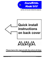
1
SoundBrick Model 500 INSTALLATION AND OPERATION MANUAL Quick install instructions on back cover Please leave this manual with the unit at all times Important warranty information enclosed SoundBrick 500 01/08/2001 TABLE OF CONTENTS What is the SoundBrick 500? ............................................................................ 4 System Overview .............................................................................................. 5 Front Panel............................................................................................... 5 Connections Panel ................................................................................... 7 Tape Preparation Instructions ........................................................................... 8 Message Length Table...................................................................................... 8 Installation ......................................................................................................... 9 Step 1 – Set the option switches.............................................................. 9 Continuous or Trigger Play, Switch 1.............................................. 9 Bandwidth, Switches 2-3............................................................... 10 Speaker On/Off Switch ................................................................. 10 Step 2 – Connections............................................................................. 10 Step 3 – Load the tape........................................................................... 12 Step 4 – Adjust Volume.......................................................................... 12 Message Play Operation ................................................................................. 13 Continuous Play ..................................................................................... 13 External Trigger...................................................................................... 13 Wall Mounting Instructions .............................................................................. 14 Troubleshooting............................................................................................... 15 Limited Warranty and Limitation of Liability..................................................... 16 FCC Notice...................................................................................................... 17 Quick Install instructions.................................................................................. 18 LIST OF FIGURES Figure 1 - Front Panel Diagram......................................................................... 5 Figure 2 - Side Panel Diagram .......................................................................... 7 Figure 3 - Option Select Switches ..................................................................... 9 Figure 4 - Installation Diagram ........................................................................ 11 LIST OF TABLES Table 1 - Play Light + Load Light Indications .................................................... 6 Table 2 - Message Length................................................................................. 8 Table 3 - Option Select Switches ...................................................................... 9 Table 4 - Load Light Indications (Tape Load).................................................. 12 Table 5 - Troubleshooting ............................................................................... 15 SoundBrick 500 2 01/08/2001 To Order Additional Systems Call: Your Avaya Communications Sales Representative 1-800-247-7000 or Avaya Communications Direct 1-800-451-2100 or The nearest Avaya Communications Authorized Dealer For Technical Assistance Avaya Communications provides a toll-free customer help-line 24-hours a day. In the USA, call the Avaya Communications Help-line at 1-800-628-2888 for assistance or your Avaya Communications Authorized Dealer. In Canada, call one of the following Technical Assistance Centers for service or technical assistance: Eastern Canada and Ottawa: 1-800-363-1882 Ontario: 1-800-387-4268 Central and Western Canada: 1-800-663-9817 SoundBrick 500 3 01/08/2001 WHAT IS THE SOUNDBRICK 500? The SoundBrick Model 500 is a solid-state digital audio recording and playback device designed to provide a continuous-loop audio source for telephone message on hold and other single-message applications. The message on hold audio program loads into the SoundBrick’s digital memory automatically from your prerecorded cassette tape and is automatically reloaded after power outages. In addition to the standard continuous-play mode, the SoundBrick 500 can also offer message play only when remotely activated by connecting devices such as buttons, switches, or motion sensors to the optional 1/8” mini-plug trigger cable. The SoundBrick 500 is the most versatile digital player of its kind, with a list of features that includes: 9 9 9 9 9 9 9 9 9 User-selectable 3.5KHz, 7.0KHz, and 7.0E KHz bandwidth 4, 8, 16, or 32 minutes of messages Internal motorized CD-style tape drawer Continuous or triggered message play Modern plastic case design User-friendly controls and indicators Wall-mountable Separate 8Ω and 1KΩ RCA output jacks Built-in 2-watt amplifier Each SoundBrick is built to exacting quality standards using state-of-the-art SMT (surface mount) assembly for outstanding reliability and years of dependable service. To get the best possible performance from your SoundBrick, please take the time to read this manual and fully familiarize yourself with how the SoundBrick works before you begin installation. Use the space below to record information about the SoundBrick and about your messaging provider. You will need this information should you require assistance installing or configuring the unit, and when you need a new audio program. Dealer name: Contact person: Phone: Address: Serial number (11 digits): Memory (circle one): SoundBrick 500 4 Min. 8 Min. 4 16 Min. 32 Min. 01/08/2001 SYSTEM OVERVIEW Front Panel The monitor speaker, tape drawer eject button, and indicator lights are located on the front panel. Main power light Monitor speaker Eject button Play, load, and status lights Figure 1 - Front Panel Diagram Main power light – When lit, indicates the power supply is connected and plugged into an AC outlet and the power switch is on. Monitor speaker – A built-in speaker, useful for previewing the tape while downloading and listening to the audio output being provided to the telephone system’s message on hold port. Note that the speaker’s volume is not adjustable. Eject button – Opens and closes the motorized tape drawer for tape loading and removal. Momentarily pushing the motorized tape drawer will also result in a closure. SoundBrick 500 5 01/08/2001 Play, Load, and Status lights Play and Load lights — These lights together indicate the current status of the unit. Play Light Load Light Indication Off Slow flash Unit Empty – no tape, no messages Off Fast flash Searching tape Off On (no flash) Loading tape now On (no flash) Off Playing message now Slow flash Off Waiting for trigger Alternating flash Tape load error Simultaneous flash Hardware error Table 1 - Play Light + Load Light Indications Status light — Not used. This light is always off. SoundBrick 500 6 01/08/2001 Connections Panel The left side panel is where the connectors are for external equipment including the power supply, the phone system that receives the SoundBrick's output, and the optional external trigger cable. Also located here are the volume (level) control, the main power switch, the internal speaker switch, and the option select (DIP) switches. Power supply connector (12VDC, 500mA, center pin positive) Power switch 3 option select (“DIP”) switches, used to set continuous or trigger mode and bandwidth. Connector for the 1/8” mini-plug trigger cable (optional part) for remote message activation Internal speaker switch RCA connectors for audio output. Separate 8Ω and 1KΩ outputs provided for impedance matching. Output level adjustment knob Figure 2 - Side Panel Diagram SoundBrick 500 7 01/08/2001 TAPE PREPARATION INSTRUCTIONS To get the best audio reproduction, it is essential to start with a high-quality recording. In order to load into memory properly, your audio tape program must conform to the following guidelines exactly. 1. 2. 3. 4. Use only normal bias (Type I) tapes not exceeding 90 minutes in capacity. Do not use high bias, chrome, or metal tapes. Do not use DOLBY or any other noise reduction system. Record your production in 2-channel mono. The audio level should average 0dB while peaking no hotter than +6dB. 5. Start the recording no later than 20 seconds from the beginning of the tape. 6. The message cannot have embedded passages averaging less than -25dB for longer than 5 seconds, because the unit interprets this as silence, signifying the end of the load. 7. There should be at least 5 seconds of silence at the end of the message to signify the end of the message. MESSAGE LENGTH TABLE Message length is determined by the memory size of your unit and the bandwidth/sample rate setting. Higher bandwidth settings provide better audio quality but also reduce the total message length. Refer to the following table to find your maximum message length. 4 Min. 4 Min. 2 Min. 90 Sec. SoundBrick 500 Memory Size Bandwidth 8 Min. 16 Min. 32 Min. 8 Min. 16 Min. 32 Min. 3.5 KHz 4 Min. 8 Min. 16 Min. 7.0 KHz 3 Min. 6 Min. 12 Min. 7.0E KHz Table 2 - Message Length 8 Sample Rate 34 KBps 69 KBps 92 KBps 01/08/2001 INSTALLATION Step 1 – Set the option switches Set the option select “DIP” switches to match your requirements for play mode, bandwidth, and speaker on/off. “off” “on” Figure 3 - Option Select Switches This example is for illustrative purposes only. Your actual switch settings will vary. A switch is “ON” when it is pointing TOWARDS the switch numbers. The switch is “OFF” when it is pointed AWAY FROM the switch numbers. In the picture shown above, switch 1 is “off” and switch 2 is “on.” Switch # 1 2-3 4 Option Message play Bandwidth Factory Test Possible Values On = Trigger play enable Off = Continuous play (MOH) 2 Off, 3 Off = 3.5KHz/34KBps 2 On, 3 Off = 7.0KHz/69KBps 2 Off, 3 On = 7.0E KHz/92KBps Not Used Table 3 - Option Select Switches IMPORTANT NOTE: Changes to the bandwidth setting do not take effect until power is recycled and the tape reloaded. Continuous or Trigger Play, Switch 1 For most applications, including message on hold, message play should be set to continuous (switch off). If the switch is on, the message will play continuously until the external trigger is plugged in. Momentarily activating the trigger will play the message once. SoundBrick 500 9 01/08/2001 Bandwidth, Switches 2-3 Sets the fidelity of audio messages. There is a trade-off between audio quality and recording time: The higher the audio quality, the less the storage time. The minutes of memory equipped on your unit (4, 8, 16, or 32) is printed on the serial number label on the bottom of the unit, and assumes a bandwidth 3.5KHz. The 7.0KHz setting provides better audio quality, but reduces the amount of recording time by one-half (i.e. a 16 minute unit can only store 8 minutes of audio). Similarly, the 7.0E KHz setting provides even better audio quality than the 7.0KHz setting, but also reduces the amount of audio storage, in this case an additional 25% over the 7.0KHz setting. See the message memory table on page 8 for audio storage times for different memory and bandwidth configurations. Speaker On/Off Switch This switch turns the internal speaker on (switch on) and off (switch off). Note the speaker’s volume cannot be adjusted. The output level knob only adjusts the level of the output signal provided to the phone system, not the volume of the internal speaker. Step 2 – Connections Locate the SoundBrick 500 within 6 feet of a 110VAC outlet. The unit is designed to be placed on a flat, level surface or securely mounted on a wall. Be sure to leave clearance for connections and adjustments. IMPORTANT NOTE: Devices that emit strong electromagnetic fields such as computer monitors and fluorescent lights may interfere with message loading, so locate the unit at least a few feet away (or farther if necessary) from such devices. To help protect against power surges and other electrical problems, the use of a quality surge suppressor strip (which is different from a standard multi-outlet power strip) is strongly recommended. Damage caused by power surges, lightning, or other electrical problems are not covered under warranty. SoundBrick 500 10 01/08/2001 12VDC power supply (included) 1/8” mini-plug trigger cable (optional) ➨ Connect to trigger hardware mono RCA cable (included) ➨ Connect to phone system’s MOH port Figure 4 - Installation Diagram Connection Instructions 1. Turn the power switch OFF. Plug the included power supply into a surgeprotected 110VAC outlet and the 12VDC jack on the SoundBrick 500. Only use the power supply provided with the unit (12VDC, 500mA, center pin positive). Many power supplies look alike, but provide different output. Using the wrong one will void your warranty and may damage the unit. 2. Connect either the 8Ω or 1KΩ audio output jack to the phone system’s MOH port using a mono RCA-to-RCA cable (included). If the sound system does not have an RCA-style input, an adapter may be required (not included). 3. Connect the optional 1/8” mini-plug trigger cable to the trigger jack if you are using this feature. SoundBrick 500 11 01/08/2001 Step 3 – Load the tape Messages load into the SoundBrick 500 from a cassette tape supplied by your messaging provider. Turn the power switch on and press the tape eject button. The motorized tape drawer on the right side of the unit opens like a CD-ROM drive on a computer. Place the tape into the drawer by gently sliding it under the retaining clip, audio side facing front, then momentarily push the drawer or press the eject button again to close the drawer. The SoundBrick detects the presence of the tape and begins the load process automatically. While waiting for the load to begin, the load light on the front panel flashes slowly. The unit rewinds the tape and plays a preview of approximately 10 seconds of the tape through the internal speaker, then pauses for 5 seconds. This pause provides an opportunity to eject the tape and cancel the load. After the pause, the tape rewinds again, and message loading begins. NOTE: Never eject the tape while it is loading. During tape load, the load light display the progress: Load Light Indication Slow flash No tape in machine or rewinding tape Fast flash Searching tape for audio On (no flash) Loading message now Table 4 - Load Light Indications (Tape Load) At the end of message loading, the tape rewinds and message play begins automatically, indicated by a solid play lamp. IMPORTANT NOTE: Once the SoundBrick is loaded and playing, the tape is not required unless a power failure occurs. Removing the tape does not affect message play. However, if you do remove the tape and later insert another one (even if it is the same tape), the SoundBrick erases its memory and starts the loading process automatically. We recommend leaving the tape in to allow automatic message reload in the event of a power outage. Step 4 – Adjust Volume After installation and loading is complete, call into the company’s phone system and ask to be placed on hold. While listening to the on-hold message, adjust the output level knob on the left side panel as needed. SoundBrick 500 12 01/08/2001 MESSAGE PLAY OPERATION The SoundBrick 500 plays the loaded audio message continuously or only when externally triggered, depending on the position of option select switch 1. Continuous Play The loaded message plays continuously. When the end of the message is reached it plays again from the beginning in a digital endless loop. External Trigger The external trigger function lets you activate message play remotely by using the optional 1/8” mini-plug trigger cable, available from your messaging provider. Electrically the trigger signal is optically coupled providing isolation, static protection and long wiring runs of up to 1500 feet. One end of the trigger cable plugs into the SoundBrick’s connections panel, the other end consists of two wires. Message play is triggered by momentarily shorting the two wires. When a trigger is detected, the loaded message plays once in its entirety. While the message is playing, any other triggers are ignored until the message is over. Only then can the trigger be activated again. SoundBrick 500 13 01/08/2001 WALL MOUNTING INSTRUCTIONS Using the screw holes on the back plate as a guide, secure two screws into the wall where you want to mount the unit. Then, hang the unit on the screws. Consider the weight of the SoundBrick when choosing a mounting wall. Make sure the wall’s construction is sufficiently strong to support the weight of the unit securely. Make sure both screws are driven into studs or other sturdy supports, not just into plain drywall. To mount in this orientation, the distance between the centerpoints of the mounting screws should be 3 11/32”. To mount in this orientation, the distance between the centerpoints of the mounting screws should be 5 3/8”. SoundBrick 500 14 01/08/2001 TROUBLESHOOTING If you have trouble installing or operating the SoundBrick 500, refer to the table below to help find a solution. If you are unable to solve the problem yourself, contact your dealer for further assistance. Problem or Indication No message plays Tape load error (play + load lights flashing alternately) Tape drawer won’t open Tape stuck in deck or deck is “eating” tapes Doesn’t trigger No power-main power light is off SoundBrick 500 Possible cause and solution Adjust output level knob. Re-load tape. Check amplifier or speakers. Tape is worn out or not prepared to guidelines – obtain another tape from your messaging provider. Power interruption occurred during loading. Possible interference from strong electromagnetic field (i.e. computer monitor or fluorescent lights) – relocate unit away from source of interference. If the drawer doesn’t open when you press the eject button, press eject again. Never eject tape during download. Follow proper tape load procedure. To remove stuck tape: Turn power off, wait 10 seconds, turn power on. Wait for deck to disengage play head before ejecting. Check trigger wiring. Check option switch 1 setting. Check the power switch (should be on). Check power pack for correct DC output voltage & current. Check power outlet to make sure it is not controlled by a switch. Table 5 - Troubleshooting 15 01/08/2001 LIMITED WARRANTY AND LIMITATION OF LIABILITY Avaya Communications warrants to you that the product will be free from defects in material and workmanship when title passes to you. If you notify Avaya Communications that the product has failed to operate as warranted within one year of the date title passes to you. Avaya Communications will, at its option, repair or replace the component or components of the product that failed to operate as warranted. Any repair or replacement components may be new or refurbished and will be provided on an exchange basis. If Avaya Communications determines that the product cannot be repaired or replaced, Avaya Communications will refund the purchase price to you. If you purchase the product directly from Avaya Communications, Avaya Communications will perform warranty repair on your premises in accordance with the terms and conditions of Avaya Communications “Business Day” or “Around-the-Clock” warranty plans. The details of Avaya Communications warranty plans may be obtained from Avaya Communications. If you purchased the product from an authorized dealer, you will be covered by Avaya Communications authorized dealer plan during the warranty period. Contact your authorized dealer for details of Avaya Communications authorized dealer warranty plan. Avaya Communications obligation to repair, replace or refund as set forth above is your exclusive remedy. The limited warranties provided above do not cover damages, defects, malfunctions or product failures caused by: • Failure to follow Avaya Communications installation, operation or maintenance instructions; • Unauthorized modification or alteration of the product or its components; • Product abuse, misuse or the negligent acts of persons not under the reasonable control of Avaya Communications; • Actions of third parties and acts of God other than power surges (e.g. lightning). This limited warranty applies only to the product purchased directly from Avaya Communications or purchased directly from an authorized Avaya Communications dealer. This limited warranty does not apply to products purchased or operated outside the United States. You may be required to provide Avaya Communications with proof of purchase before Avaya Communications will perform any warranty replacements. EXCEPT AS SPECIFICALLY SET FORTH ABOVE, AVAYA COMMUNICATIONS, ITS AFFILIATES, SUPPLIERS AND DEALERS MAKE NO WARRANTIES, EXPRESS OR IMPLIED, AND SPECIFICALLY DISCLAIM ANY WARRANTY OF MERCHANTABILITY OR FITNESS FOR A PARTICULAR PURPOSE. EXCEPT FOR PERSONAL INJURY, THE LIABILITY OF AVAYA COMMUNICATIONS, ITS AFFILIATES, SUPPLIERS AND DEALERS FOR ANY CLAIM. LOSS. DAMAGE OR EXPENSE FROM ANY CAUSE WHATSOEVER, REGARDLESS OF THE FORM OF THE ACTION, WHETHER IN CONTRACT, TORT OR OTHERWISE, SHALL NOT EXCEED THE LESSER OF DIRECT DAMAGES PROVEN OR THE REPAIR OR REPLACEMENT COST OF THE SYSTEM OR THE SYSTEM’S PURCHASE PRICE. IN NO EVENT SHALL AVAYA COMMUNICATIONS, ITS AFFILIATES, SUPPLIERS AND DEALERS BE LIABLE FOR INCIDENTAL, RELIANCE, CONSEQUENTIAL OR ANY OTHER INDIRECT LOSS OR DAMAGE (INCLUDING LOST PROFITS OR REVENUES SUSTAINED OR INCURRED IN CONNECTION WITH THE SYSTEM). THIS LIMITATION OF LIABILITY SHALL SURVIVE FAILURE OF THE EXCLUSIVE REMEDY SET FORTH IN THE LIMITED WARRANTY ABOVE. 16 SoundBrick 500 01/08/2001 FCC NOTICE RADIO AND TELEVISION INTERFERENCE This equipment has been tested and found to comply with the limits for a Class A digital device, pursuant to Part 15 of the FCC rules. These limits are designed to provide reasonable protection against harmful interference in a residential installation. This equipment generates, uses and can radiate radio frequency energy and, if not installed and used in accordance with the instructions, may cause harmful interference to radio communications. However, there is no guarantee that interference will not occur in a particular installation. If this equipment does cause harmful interference to radio or television reception, which can be determined by turning the equipment off and on, the user is encouraged to try to correct the interference by one or more of the following measures: - Reorient or relocate the receiving antenna. - Increase the separation between the equipment and the receiver. - Connect the equipment into an outlet on a circuit different from that to which the receiver is connected. - Consult the dealer or an experienced radio/TV technician for help. You may also find helpful the following booklet, prepared by the FCC: "How to Identify and Resolve Radio-TV Interference Problems." This booklet is available from the U.S. Government Printing Office, Washington D.C. 20402. Changes and Modifications not expressly approved by the manufacturer or registrant of this equipment can void your authority to operate this equipment under Federal Communications Commissions rules. This digital apparatus does not exceed the Class A limits for radio noise emissions from digital apparatus set out in the Radio Interference Regulations of the Canadian Department of Communications. Le present appareil numerique n'emet pas de bruits radioelectriques depassant les limites applicables aux appareils numeriques de la class A prescrites dans le Reglement sur le brouillage radioelectrique edicte par le ministere des Communications du Canada." SoundBrick 500 17 01/08/2001 QUICK INSTALL INSTRUCTIONS 12VDC power supply (included) 1/8” mini-plug trigger cable (optional) ➨ Connect to trigger hardware mono RCA cable (included) ➨ Connect to phone system’s MOH port For more detailed instructions, read the inside of the manual. 1. Consult message length table on page 8 if needed. Set option (DIP) switches: --Message play, switch 1 (off = continuous play MOH, on = trigger play enable) --Bandwidth, switches 2-3 (see table 3, page 9) Note: A switch is on when it is pointing towards the switch numbers and off when it is pointing away from the switch numbers. 2. Connect the power supply and phone system as shown above. Connect optional trigger cable, if applicable. 3. Turn the power switch on. Press the eject button on front of the SoundBrick to open the motorized tape drawer. Insert the cassette into the tape drawer by gently sliding it underneath the retaining clip, audio side facing front, then momentarily push the drawer or press the eject button again to close the drawer. 4. A 10-second preview of the tape is played through the internal speaker. This can only be heard if the speaker is on. The tape then rewinds and begins to load into memory automatically. After tape load, message playback begins automatically. 18 SoundBrick 500 01/08/2001