1
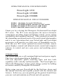
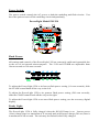
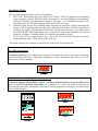
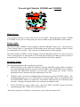
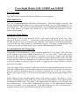
POWERLIGHT
Operator’s Manual
PowerLight 1250
PowerLight 1250DR
PowerLight 2500DR
&
Remote Control Accessories
Unit Number Assignment, Page 14
PLDIR-2 and PLDIR-1 Remote Digital Display, Page 15
PLIRC-1 Infrared Remote Controller, Page 16
1
OPERATOR MANUAL FOR MONOLIGHTS
PowerLight 1250
PowerLight 1250DR
PowerLight 2500DR
OPERATOR MANUAL FOR ACCESSORIES
PLDD-1 side display for model PL1250 only.
PLDC-1 side display/manual controller for “DR” models.
PLDIR-2 side display & IR receiver for “DR” models.
PLIRC-1 hand held remote control for “DR” models.
Thank you for selecting the Photogenic Professional PowerLight
PL2 series. The PL2 series incorporates the newest electronic
components providing improved lighting control, power setting
repeatability and expanded functions. These products are built for
the demanding operational needs of the professional photographer
and it is our expectation that your PowerLight and PowerLight
accessories will provide you with years of dependable service.
With this new PL2 series optional accessories include: remote
power displays, manual and infrared remote control and computer
software to control and save your power and modeling power
settings.
INTRODUCTION
The PowerLights are a self-contained light unit and power supply.
They have a professional plug-in flashtube, a
250 watt adjustable quartz modeling light, and bare bulb
capability, both vertically and horizontally. The PowerLights are
fitted with Photogenic’s unique quick-change system for holding
accessories made by Photogenic Professional.
Before using your new PowerLight for the first time, please read
this manual carefully and acquaint yourself with the controls and
features. In this way, you can quickly get the greatest benefit from
your new unit and maintain an efficient and safe operation.
2
SAFETY PRECAUTIONS
Despite the measures that have been taken to make electronic flash equipment safe, it
must be recognized that high voltages and high temperatures do exist within the power
supply / lighting unit. Certain precautions must be observed in handling the unit. Contact
with internal high voltage may result in severe injury or death.
1.
2.
3.
4.
5.
6.
7.
8.
9.
Before installing or removing the flashtube and modeling lamp, be sure this
appliance is turned off, cooled and unplugged from AC power source.
Do not touch the glass tubes with bare hands, as normal body oils will shorten the
bulb’s life. Always use a clean cloth or wear gloves to protect your hand from glass
breakage and heat.
Do not defeat the purpose to the three-wire line cord by disconnecting the ground.
Connect to properly functioning and grounded 3-pin receptacles only. If you are
using an extension cord, be sure the cord has an equivalent or greater rating and has
a ground.
Do not insert a screwdriver or other metal objects into the flashtube socket area or
vents. Contact with high voltage may result.
Do not operate this appliance with a frayed or damaged line cord. When replacing
or using the unit with an extension cable, be sure the cable has an equivalent or
greater rating and is a properly connected 3-wire grounded cable.
Do not attempt to use this appliance if it has been dropped or damaged, until a
qualified service person has serviced it.
Do not operate the unit with a damaged or broken flashtube or modeling lamp. Do
not use flashtubes with broken, cracked or missing glass envelopes. To prevent
damage always use Photogenic specified replacements for the flashtubes and
modeling lamps.
Perform no internal service work on this unit. Refer all such service to a qualified
service person or return to the factory. This will provide you safety and
continuation of your warranty.
Do not operate when water is present and from extreme temperature shifts. If the
unit is stored in hot or below freezing temperatures, allow at least one hour at room
temperatures before using.
PREPARATION AND BASICS
Unpacking and Setup:
Unpack all units carefully to remove all parts from the carton(s). Do not discard or
destroy the packing material until the equipment has been inspected, assembled, and all
parts accounted for.
After unpacking, all parts should be examined for any damage, which may have been
caused by rough handling during shipment. If any damage is detected, contact the
delivering carrier at once. Claim for damage should be made to the delivering carrier
before destroying packing cartons.
To set up the unit, first mount and secure it on a suitable stand. The PowerLight stand
adapter allows the unit to be mounted on a stand with a 3/8” to 5/8” post. Be sure to use
a stand that is stable and will not tip easily.
3
Unpacking and Setup: (continued)
The unit is shipped with the modeling lamp and flashtube not installed. While installing
the modeling lamp and flashtube (with glove or clean cloth to protect the hand) be sure
they are properly inserted and tight to avoid arcing and failure of the socket contacts
during operation. Do not touch the glass tubes with bare hands, as normal body oils will
shorten the bulb’s life. Always use a clean cloth or wear gloves to protect your hand
from glass breakage and heat.
The 7 1/2 inch reflector is attached by the “quick-change” mechanism. Three tabs on the
unit grip the ring on the reflector. Finger levers located on the top of the unit control two
of these tabs. To mount the reflector, squeeze the finger levers towards each other and
tilt the reflector past the stationary top-tab, then past the two tabs that are controlled with
the levers. Release the finger levers and make sure all three tabs are securing the
reflector (see illustration below.) All PowerLight accessory reflectors and soft boxes are
designed for use with this “quick-change” system or onto this 7 _ inch reflector.
Squeeze levers to mount
reflector in locked position.
Punch out hole for
umbrella rod.
Professional plug-in
flashtube.
With power switch OFF, attach the line cord to the power-input connector,
located on the bottom of the PowerLight, and connect it to a grounded wall
outlet. Turn the power switch ON. The READY light will light when the unit
has charged to the power level set by the FLASH power control.
4
CONTROL PANEL AND BASIC OPERATION:
tm
tm
Power Input:
The power required to operate the PowerLight 1250, 1250DR or 2500DR is 105 to 125
volts AC, 60 Hz, 10 Amp. The power cord has a 125V, 10 Amp. rating. Replacement
cords or extension cords rated for less amperage may overheat and should not be used
with PowerLights.
Circuit Protection:
Circuit protection automatically protects this appliance from excessive damage due to
circuit or component failure. Operation exceeding the rated cycle of the appliance may
cause the fuse to open. [Always replace fuse with same rating of fuse.] An additional
thermal protector is located inside the PowerLight and may open, if the rated duty cycle
is exceeded. A cooling off period of 10 to 45 minutes is required to reset the thermal
fuse.
To replace a blown fuse (power cord must be disconnected), simply unscrew the fuse
holder cap (bottom of unit) and replace the exposed fuse with a new fuse. If fuses
continue to blow, contact your dealer or qualified service person. (See specification
section for fuse replacements)
5
Power Switch:
The power switch controls the AC power to both the modeling and flash circuits. You
have the option to turn-off the modeling circuit independently.
PowerLight Model PL1250
tm
tm
Flash Power:
All settings and controls of the PowerLight 1250 are extremely stable and repeatable due
to the use of an internal microcomputer. The 1250 and 1250DR are adjustable from
16watt seconds to 500 watt seconds.
To adjust the PowerLight 1250 to its lowest flash power setting (16 watt seconds), slide
the FLASH control knob all the way to the left.
To adjust the PowerLight 1250 to its greatest flash power setting (500 watt seconds),
slide the FLASH control knob all the way to the right.
To adjust the PowerLight 1250 to an exact flash power setting, use the accessory digital
display.
Ready Light:
The PowerLight 1250 is fully charged when the READY lamp is on. Lowest power
(16ws) charge time is a maximum of .5 seconds and at full power charge (500 ws) time is
a maximum of 1.5 seconds. The unit may be flashed before fully charged.
6
Modeling Light:
The modeling light has three modes of operation:
1. MANUAL adjustment [press the MANUAL button, LED on] adjusts the modeling
lamp intensity with the MODEL slide control knob. As with flash power, minimum
setting is full left and maximum setting is full right. The MODEL intensity scale
corresponds to the FLASH intensity scale, measured in f-stops.
2. TRACK mode causes the modeling lamp intensity to track the FLASH control knob
setting. The modeling lamp may be set to full intensity at any FLASH control knob
position, by simply pressing the TRACK/SET button a second time, (you will notice
the TRACK/SET LED light blink once) with the FLASH control knob in the desired
position. Setting is retained when user returns from another mode.
3. FULL ON/OFF is exactly what it says. Press the FULL ON/OFF button to turn the
modeling lamp OFF (LED off) or ON (LED on).
All mode settings are retained, even after the power has been turned off.
PL1250 Accessories:
A Digital Display for the flash power setting is available as well as the large assortment
of PowerLight reflectors, umbrellas, softboxes, snoots, barndoors and cases. (See the
listing later in this manual)
PL1250DR and PL2500DR Accessories:
A Remote Digital display/flash control, a Remote Digital Display & Infrared Receiver
and a hand-held Infrared Controller are available, as well as the large assortment of
PowerLight reflectors, umbrellas, soft boxes, snoots, barndoors and cases. (See the listing
later in this manual)
1
2
3
4
6
7
8
9
5
tm
7
PowerLight Models 1250DR and 2500DR
tm
1
2
1
10
tm
Flash Power:
Use the Adjust button to turn on the Flash ws red LED. Adjust the PowerLight 1250DR
or 2500DR Flash power setting using the 1/2 or 1/10 f-stops UP/DOWN arrow buttons.
Ready Light:
The PowerLight 2500DR is fully charged when the READY lamp is on. Lowest power
(32ws) charge time is a maximum of .8 seconds and at full power charge (1000 ws) time
is a maximum of 3 seconds. The unit may be flashed before fully charged.
The PowerLight 1250DR is fully charged when the READY lamp is on. Lowest power
(16ws) charge time is a maximum of .5 seconds and at full power charge (500 ws) time is
a maximum of 1.5 seconds. The unit may be flashed before fully charged.
Modeling Light:
The modeling light has three modes of operation:
1. MANUAL [press the ADJUST button to turn the MODEL yellow LED on] adjusts
the modeling lamp intensity using the 1/2 or 1/10 f-stops UP/DOWN arrow buttons.
Pressing the MANUAL button a second time will change the mode to flash
adjustment and is indicated by the illuminated red LED
2.
TRACK mode causes the modeling lamp intensity to track the FLASH setting. The
modeling lamp may be set to full intensity at any FLASH value, by simply pressing
the TRACK/SET button a second time, with the FLASH already set to desired wattseconds. Setting is retained when user returns from another mode.
3.
FULL ON/OFF is exactly what it says. Press the FULL ON/OFF button to turn the
modeling lamp OFF (LED off) or ON (LED on).
All mode settings are retained, even after the power has been turned off.
8
PowerLight Models 1250, 1250DR and 2500DR
Test Function:
The TEST button is pressed to fire the flashtube for test purposes.
Flash Indication:
The PowerLight indicates the flash has fired properly. The flash indication feature will
dim the modeling light to its lowest setting, then intensify slowly to full brightness or to
its original state. This will occur after each flash, even though the modeling light may be
off. This feature is turned ON (LED on) or OFF (LED off) with the F L A S H
INDICATION button.
Automatic Flash Dump:
This feature is set at OFF from the factory, but can be turned on by the user. (See
advanced features section)
This feature will automatically flash the unit when the
FLASH setting is lowered; otherwise, the internally stored power is discharged through a
resistor, before the unit is READY. Flash Dump is faster. The units recharge quickly and
reducing your power setting slowly may result in additional flash discharges.
Synchronization and Triggering:
Triggering is accomplished by using a built-in photoslave or a trigger cable from the
power supply to the camera shutter contacts of ”X” or “zero” delay. Other units in the
system are then triggered by photoslave operation. It is best to connect the fill light
directly to the camera since it will be positioned furthest back in the studio and will
usually provide sufficient illumination to trigger the other units. It is suggested that all
walls and ceiling be painted either in white or light neutral colors for most reliable
photoslave operation.
After the trigger cord is properly connected, check the synchronization with the camera.
Adjust the lighting unit to same height as the camera lens and face the lights into the lens.
The lens aperture should be open to its fullest extent and set on “X” or “zero” delay.
Remove the camera back. It is best to perform this test with the modeling lamps turned
off.
While looking at the lens through the back of the camera, operate the shutter. A few
sheets of white paper in front of the lens will cut down the brilliance of the flash and aid
in making the observation. The flash of the light should then appear as a circle the same
size as the aperture. If the circle is flattened on the sides, or if no light appears through
the lens, the shutter is not synchronized. If the shutter appears not to be synchronized, a
reputable camera repair shop should check the shutter contacts.
9
OPERATION
PowerLight Model 1250 and 1250DR
Flashing Rate:
The unit recharges quickly, as indicated by the READY light on the control panel. A
quick series of flashes can be obtained within the limits of the recharge time. Continuous
rapid flashing, however, can overheat and damage the flashtube and internal parts. The
maximum recommended rate of flashing depends upon the power level being used and
the amount of operation time. Use the following chart to serve as a guide for the
maximum rate to use in your situation.
Power
Operating
Sec.Between
Number of
Level
Time
Flashes.
Flashes.
Full
Continuous
30 minutes
3 minutes
15
6
4
Continuous
300
45
1/4
Continuous
30 minutes 3
minutes
6
3
2
Continuous
600
90
1/32
Continuous
1.5
Continuous
Exposure Information:
The following charts give the BCPS output for various umbrellas and reflectors.
Coverage angle is given in degrees.
Umbrella
32 inch
45 inch
60 inch
Coverage
120 degree
120 degree
120 degree
Full Power
Half
Quarter
Eighth
Sixteenth
Thirty-Second
5500
2750
1375
688
344
5583
2792
1396
698
349
174
5583
2792
1396
698
349
174
Reflector
Diameter
Coverage
Full
Half
Quarter
Eighth
Sixteenth
Thirty-Second
GN@ ASA 100
172
None
360°
7 1/2”
35°
14”
40°
16”
60°
20”
65°
24”
145°
2333
1167
583
292
146
73
110
25000
12500
6250
3125
1562
781
365
17500
8750
4375
2188
1094
547
305
23333
11667
5833
2916
1458
729
350
16333
8167
4083
2042
1021
510
295
4200
2100
1050
525
262
131
150
10
SPECIFICATIONS
PL1250 & PL1250DR
General:
Flash Power....................................................16 to 500 watt-seconds.
maximum (6 f-stops)
Flash Duration................................................1/1300 second at Full
1/640 second at 1/32
Recycling time................................................0.5 to 1.5 seconds
Power Control.................................................Full to 1/32 range.
(6 f-stops)
0.1 f-stop resolution.
Digital Display Accessory
Modeling Light Power ...................................250 Watt Quartz, ESS
Modeling Light Control .................................Full to 1/32 range.
0.1 f-stop resolution.
Line voltage regulated.
Triggering ......................................................Built in Photoslave.
Push to Test button.
Synchronization Jack.
5 volt isolated.
Main Supply .................................................105-125 VAC, 60 Hz, 10 amp.
Consumption ................................................ 0.2 amps idling,
15 amps charge.
Voltage Stabilization ..................................... Plus or minus 0.05 f-stop.
Overload Protection .......................................Fuse. 3AG type,
15 Amp, SLO-BLO.
Packaging .......................................................Extruded Aluminum case.
Weight ............................................................5 pounds, 8 ounces.
Dimensions (housing only).............................4.5” x 4.5” x 6.75”
Flashtubes and Modeling Lamps:
Flashtube ....................................................Plug-in style, use only
Photogenic’s Standard C4-15
or C4-15C or C4-15F.
Modeling Lamp ..........................................250-Watt Quartz Halogen, ESS.
150-Watt Quartz Halogen, ESP.
100-Watt Quartz Halogen, ESR.
Fuse ............................................................3AG type, 15 Amp, SLO-BLO.
11
OPERATION
PowerLight Model 2500DR
Flashing Rate:
The unit recharges quickly, as indicated by the READY light on the control panel. A
quick series of flashes can be obtained within the limits of the recharge time. Continuous
rapid flashing, however, can overheat and damage the flashtube and internal parts. The
maximum recommended rate of flashing depends on the power level being used and the
amount of operation time. Use the following chart to serve as a guide for the maximum
rate to use in your situation.
Power
Operating
Sec.Between
Number of
Level
Time
Flashes.
Flashes.
Full
Continuous
30 minutes
3 minutes
15
10
6
1/4
Continuous
30 minutes 3
minutes
6
3
3
Continuous
600
60
1/32
Continuous
3
Continuous
Continuous
180
30
Exposure Information:
The following charts give the BCPS output for various umbrellas and reflectors.
Coverage angle is given in degrees.
Umbrella
32 inch
45 inch
60 inch
Coverage
Full Power
Half
Quarter
Eighth
Sixteenth
Thirty-Second
Reflector
Diameter
Coverage
120 degree
11000
5500
2750
1375
688
344
120 degree
11166
5583
2792
1396
698
349
120 degree
11166
5583
2792
1396
698
349
None
360°
7 1/2”
35°
14”
40°
16”
60°
20”
65°
24”
145°
Full
Half
Quarter
Eighth
Sixteenth
Thirty-Second
4666
2333
1167
583
292
146
50000
25000
12500
6250
3125
1562
35000
17500
8750
4375
2188
1094
46666
23333
11667
5833
2916
1458
32666
16333
8167
4083
2042
1021
8400
4200
2100
1050
525
262
GN@ ASA 100
160
515
430
495
415
210
12
SPECIFICATIONS
PL2500DR
General:
Flash Power................................................
32 to 1000 watt-seconds
maximum. (6 f-stops)
Flash Duration............................................ 1/770 second at Full
1/345 second at 1/32
Recycling time................................................0.8 to 3.0 seconds
Power Control.................................................Full to 1/32 range.
0.1 f-stop resolution.
Digital Display &
Control Accessory
Modeling Light Power ...................................250 Watt Quartz, ESS
Modeling Light Control .................................Full to 1/32 range.
0.1 f-stop resolution.
Line voltage regulated.
Triggering ......................................................Built in Photoslave.
Push to Test button.
Synchronization Jack.
5 volt isolated.
Main Supply ................................…..............105-125 VAC, 60 Hz, 10 Amp.
Consumption ................................................. 0.2 amps idling,
15 amps charge.
Voltage Stabilization ..................................... Plus or minus 0.05 f-stop.
Overload Protection .......................................Fuse. 3AG type,
15 Amp, SLO-BLO.
Packaging ......................................................Extruded Aluminum case.
Weight ............................................................7 pounds.
Dimensions (housing only).............................4.5” x 4.5” x 8.75”
Flashtubes and Modeling Lamps:
Flashtube ................................................... Plug-in style, use only
Photogenic’s Standard C4-19
or C4-19C.
Modeling Lamp ..........................................250-Watt Quartz Halogen, ESS.
150-Watt Quartz Halogen, ESP.
100-Watt Quartz Halogen, ESR.
Fuse ............................................................3AG type, 15 Amp, SLO-BLO.
13
ADVANCED POWERLIGHT FEATURES.
Models PL1250, PL1250DR, and PL2500DR
Automatic Dump Flash
This feature will automatically flash the unit when the FLASH setting is lowered;
otherwise, the internally stored power is discharged through a resistor, before the unit is
READY. Flash Dump is faster. This feature can be turned on or off, by the user.
Turn FLASH DUMP on: Turn PowerLight AC power off. With unit power off, press and
hold the FULL ON/OFF button. While holding the FULL ON/OFF button, turn the unit
power on and wait until the FULL ON/OFF LED blinks. Next, release the FULL
ON/OFF button and the FULL ON/OFF LED will go off.
Turn FLASH DUMP off: Turn PowerLight AC power off. With unit power off, press
and hold the MANUAL button. While holding the MANUAL button, turn the unit power
on and wait until the MANUAL LED blinks. Next, release the MANUAL button and the
MANUAL LED will go off.
Also, each time the AC line power is disconnected or switched off, the flashtube will
flash. This removes most of the flash capacitor charge to prolong the life of the unit and
is a much safer condition for storage, transporting, and replacement of flash tube or
modeling lamp. This is a feature, over which the user has no control.
ADVANCED POWERLIGHT FEATURES.
Models PL1250DR, and PL2500DR only.
Unit Number Assignment
This feature allows the user to assign a UNIT NUMBER (1 to 9) to each DR type
PowerLight in the studio. The UNIT NUMBER is necessary when INFRARED remote
control is used (see accessories.)
To assign a UNIT NUMBER: Turn PowerLight AC power off. With unit power off,
press and hold the 1/2 UP arrow button. While holding the 1/2 UP arrow button, turn the
unit power on. Digital display should be “un #”, where # means some number 1 to 9.
Next, release the 1/2 f-stop UP arrow button. Change the UNIT number using the 1/10
UP/DOWN arrow buttons. Close the assignment feature and save the UNIT number by
pressing the 1/2 UP arrow button.
14
Advanced PL2 series Accessories.
PLDD-1 Digital display for Model 1250 only.
The PLDD-1 is a digital display to enhance the resolution and repeatability of the Model
1250’s Flash analog slide-pot control. It displays only Flash power, over the full range
of 16 to 500 watt-seconds. Resolution of the PLDD-1 is 0.1 f-stop.
The PLDD-1 should be mounted to the umbrella bracket under the housing of the Model
1250 PowerLight, on flexible rotating mount, or on an extension cable, for better
viewing.
PLDRC-1 Remote digital display and flash adjustment for models
1250DR and 2500DR.
The PLDRC-1 is a digital display to enhance the visibility of, and to change the Flash
power setting. It displays and controls only Flash power, over the full range of wattseconds. Resolution is 0.1 f-stop, using the 1/2 f-stop and 0.1 f-stop UP/DOWN buttons.
The PLDRC-1 should be mounted to the umbrella bracket under the housing of the
PowerLight, on rotating mount, or on an extension cable, for better viewing and easier
control accessibility.
PLDIR-2 Remote digital display and Infrared receiver for models
1250DR and 2500DR. (must be used with PLIRC-1 controller)
The PLDIR-2 is a digital display to enhance the visibility of, and to receive infrared
signals to control all functions of the 1250DR and 2500DR PowerLights. It displays both
Flash power and Modeling lamp power and unit number. It has a green READY
indicator and a BI-color indicator for Flash or Model. Behind a small window is an
infrared receiver. Resolution is 0.1 f-stop.
The PLDIR-2 should be mounted to the umbrella bracket under the housing of
the PowerLight, on rotating mount, or on an extension cable, for better viewing
and infrared control.
15
Advanced PL2 series Accessories.
PLIRC-1 Infrared remote controller for models 1250DR and 2500DR.
(must be used with PLDIR-1 receivers)
Similar to TV, VCR, DTV universal remote controllers, the PLIRC-2 can control up to
nine (9) PowerLights with individual settings. If several PowerLights are used with
identical settings the same unit number can be assigned to them. This will expand the
total number of lights that can be controlled with the PLIRC-2. All panel button controls
are available, plus STANDBY.
All PowerLights must have PLDIR-2 infrared receivers and have their unique unit
numbers assigned. PowerLights may have identical unit number numbers, if they are to
be operated exactly the same, under all studio arrangements.
Select a Unit Number on one of the top ten buttons, then control the PowerLight with the
lower buttons, observing the PowerLight digital display for the changes.
The All button, under Unit Number, transmits the changes to all active PowerLights. This
enables the photographer to raise or lower flash or model levels on all the units, without
the laborious task of changing them all, individually.
STANDBY lets the photographer put all the PowerLights into a standby state to stop
public photographers from slaving the units at a wedding, or some studio units can be put
in standby when not required for a shot. The infrared control can easily reach to units on
12-foot stands (it has been tested to 100 feet, indoors.)
PLIBM-1 Studio System Controller software for IBM compatibles.
(must be used with PL1250DR & PL2500DR with PLDIR-2 receivers.)
Along with infrared transmitter hardware and an IBM compatible computer using
Windows 95 or 98, the software is used by the photographer to specify the PowerLight
settings for up to nine units with independent settings and save a studio settings or as a
pose file. An unlimited number of pose files may be saved. All PowerLights must have
PLDIR-2 infrared receivers.
PLMAC-1 Studio System Controller software for MAC. (must be used with
PL1250DR & PL2500DR with PLDIR-2 receivers.)
Along with infrared transmitter hardware and a MAC computer using Windows 95 or 98,
the software is used by the photographer to specify the PowerLight settings for up to nine
units with independent settings and save a studio settings as a pose file. An unlimited
number of pose files may be saved. All PowerLights must have PLDIR-2 infrared
receivers.
PLX-5
Five foot extension cable with adapter for PLDD-1, PLDRC-1 and PLDIR-2
displays.
PLX-10 Ten foot extension cable with adapter for PLDD-1, PLDRC-1 and PLDIR-2
displays.
PLX-15 Fifteen foot extension cable with adapter for PLDD-1, PLDRC-1 and PLDIR-2
displays.
16
POWERLIGHT QUICK CHANGE ACCESSORIES
REFLECTORS:
PL7R
7 1/2” Standard high grain reflector. 35 degree coverage.
PL14R
14” Parabolic for portraits, feathering, flood and fill lighting.
60 degree coverage.
PL16R
16” Parabolic for portraits, feathering, flood and fill lighting.
60 degree coverage.
PL16BD
16” 2-panel clamp-fit barndoor & diffuser.
PL16BDK
16” 4-panel barndoor and diffuser.
PL20R
20” Parabolic for portraits, feathering, flood and fill lighting.
65 degree coverage.
PL20BD
20” 2-panel clamp-fit barndoor & diffuser
PL24R
24” Parabolic for soft illumination and flood lighting.
100 degree coverage.
PL3R
Shallow Background reflector rotates to control light for high key & back
lighting.
PL3RV
Veil Slotted Background reflector for veil and burst-lighting effects.
PL5R
Deep Conical Background reflector.
PL5AK
Gel & Diffuser holder for Deep background reflector.
PL7MF
Accessory mounting frame for 7 _” reflector.
PL7BDK
4-panel barndoor, frame and diffuser kit for PL06-R.
Diffuser available separately
PL7SNK
3” & 5” snoot kit with diffuser and mounting frame.
Snoots also available separately.
PL7GK
Fine & coarse grids with diffuser and mounting frame.
Grids also available separately
PLCW
Counter weight for PowerLights. Used with soft boxes, umbrellas and
large reflectors.
PLH
Tilting handle for PowerLights. Makes an adjustment easier for light
direction.
17
POWERLIGHT QUICK CHANGE ACCESSORIES
UMBRELLAS:
EC32BC
EC45BC
EC60BC
EC32S
EC45S
EC60S
32” White satin flat panel inner umbrella with black blocking outer
umbrella.
45” White satin flat panel inner umbrella with black blocking outer
umbrella.
60” White satin flat panel inner umbrella with black blocking outer
umbrella.
32” Silver satin flat panel inner umbrella with black blocking outer
umbrella.
45” Silver satin flat panel inner umbrella with black blocking outer
umbrella.
60” Silver satin flat panel inner umbrella with black blocking outer
umbrella.
SOFTBOXES:
SB12x36
SB24x32
SB36x48
SB48x72
SB22
SB36
OB48
12”x36” Satin white front panel, silver inner panels with black blocking
outer and Quick-Change bracket.
24” x 32” Satin white front panel, silver inner panels with black
blocking outer and Quick-Change bracket.
36”x 48” Satin white front panel, silver inner panels with black blocking
outer and Quick-Change bracket.
48”x 72” Satin white front panel, silver inner panels with black
blocking outer and Quick-Change bracket.
22”x22” Satin white front panel, silver inner panels with black blocking
outer and Quick-Change bracket.
36”x36” Satin white front panel, silver inner panels with black blocking
outer and Quick-Change bracket.
48” Octagon - 48” Satin white front panel, silver inner panels with black
blocking outer and Quick-Change bracket.
SERVICE
The photographer should not attempt to make repairs.
Consult a dealer for an authorized Photogenic Professional Lighting service agent. This
will provide you safety, insure proper operational functions and provide continuation of
your warranty.
For replacing the flashtube or modeling lamp, follow the directions and specifications
given earlier in this manual in the setup section.
Before removing the old tubes or installing new tubes, always unplug your
PowerLight and discharge the stored energy by pressing the “test” button. Wait
approximately two hours for the main capacitors to deplete any residual stored
wattage. Never place your fingers or any metal objects into the flash or
modeling sockets. Contact with high voltage may result.
18
General Trouble Shooting
COMMON PROBLEMS AND CAUSES
Unit does not charge.
Probable causes:
a. Fuse blown. (Unplug and discharge the unit-Replace fuse.)
b. No line power to unit. (Check line cord and outlet.)
c. Unit is on, but will not charge. (Safety thermal detector activated by heavy
use, beyond specified Flashing Rates on page 9.)
d. Unit completely off, but is connected to power and is turned on. (Safety
thermal switch activated by internal discharge. Decreasing flash power
setting repeatedly with the down arrow key or placing the unit into
STANDBY with the remote control repeatedly causes the flash power to
discharge through an internal power resistor. If the resistor over-heats, a
thermal switch will open and cut off line power to the unit. After a 3minute cool-off period, the power will return. This is a unit-protecting
feature and can be caused by user actions or circuit failure.)
Modeling light does not turn on.
Probable causes:
a. Lamp turned off. (Press FULL ON/OFF button until LED lights.)
b. Lamp burned out. (Inspect and replace, when cool. See SERVICE section
of this manual)
Light flashes by itself without apparent reason.
Probable causes:
a. Defective trigger cord, or trigger cord incorrectly polarized.
b. Bright light falling on photoslave.
c. Poor connection in line cord.
d. Reverse connection on trigger cord connection at camera.
e. Some radio slaves will cause interference-consult slave manufacturer.
Trigger cord will not flash unit, but charge indicator shows that the system has charged.
Probable causes:
a. Defective trigger cord.
b. Defective flashtube. Turn unit off. Wait until cool, then replace flashtube.
(See SERVICE section of this manual)
19
Limited PowerLight Warranty
Photogenic Professional Lighting warranties the “standard line” of new
PowerLight products to be free from defects in material and workmanship
of the PL2 series of PowerLights for a period of two years from
date of purchase. At our choice, we will repair or replace any PL2,
Solair or Voltage Smart series light that is deemed to be defective.
This warranty does not cover damages caused by shipping, product
abuse or use other than the intended photographic applications.
Any product modifications will render this warranty void. Use of
other manufacturer’s accessories, which restrict normal or intended
operation (especially venting airflow), may cause damage and will void
this warranty. Flash tubes are warranted under the above conditions
for one year from date of purchase. Modeling lamps are covered for
initial use failures only.
Photogenic Professional Lighting
1268 Humbracht Circle, Bartlett, Illinois 60103-1631
www.PhotogenicPro.com
Telephone: (630)830-2500 Fax: (630)830-2525
MANUAL PART NO. 015756-00V3-05
20