1
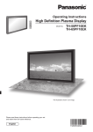
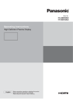
Operating Instructions
High Definition
Custom Home Theater Plasma Display
Model No.
TH-50VX100E
TH-65VX100E
The illustration shown is an image.
Please read these instructions before operating your set and retain them for future reference.
English
TQBC2382-1
Dear Panasonic Customer
Welcome to the Panasonic family of customers. We hope that you will have many years of
enjoyment from your new Plasma Display.
To obtain maximum benefit from your set, please read these Instructions before making
any adjustments, and retain them for future reference.
Retain your purchase receipt also, and note down the model number and serial number of
your set in the space provided on the rear cover of these instructions.
Visit our Panasonic Web Site
http://panasonic.net
Table of Contents
Important Safety Notice ........................................... 3
Safety Precautions ................................................... 4
Accessories .............................................................. 7
Accessories Supply ................................................. 7
Remote Control Batteries ........................................ 7
Connections .............................................................. 8
PC Input Terminals connection ................................ 9
SERIAL Terminals connection ............................... 10
HDMI connection ....................................................11
COMPONENT / RGB connection ...........................11
Power On / Off......................................................... 12
Initial selections...................................................... 13
Selecting the input signal ...................................... 13
Selecting the On-Screen Menu Language ............ 13
Basic Controls ........................................................ 14
Scrolling bar and Test patterns functions.............. 16
EXT. SCALER function ......................................... 16
ASPECT Controls ................................................... 17
On-Screen Menu Displays ..................................... 18
Picture Adjustments ............................................... 20
Advanced settings ................................................. 22
Picture Profiles ...................................................... 24
Saving profiles ...................................................... 25
Loading profiles .................................................... 26
Editing profiles ...................................................... 27
Locking profiles .................................................... 28
Adjusting Pos. /Size ............................................... 30
Sound Adjustment .................................................. 32
SDI sound Output .................................................. 32
Screensaver (For preventing image retention) .... 33
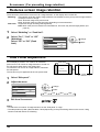
Reduces screen image retention ........................... 34
Side Panel Adjustment .......................................... 34
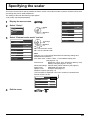
Specifying the scaler............................................. 35
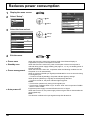
Reduces power consumption ............................... 36
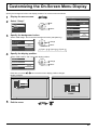
Customizing the On-Screen Menu Display ......... 37
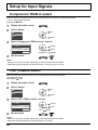
Setup for Input Signals .......................................... 38
Component / RGB-in select ................................... 38
YUV / RGB-in select .............................................. 38
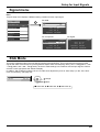
Signal menu .......................................................... 39
XGA Mode ............................................................. 39
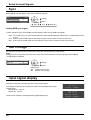
Sync ...................................................................... 40
SDI Through .......................................................... 40
Input signal display ................................................ 40
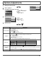
Options Adjustments ............................................. 41
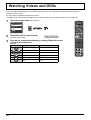
Watching Videos and DVDs .................................. 42
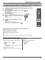
Programming the Remote to Operate Peripheral
Equipment ............................................................ 43
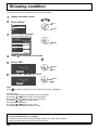
Shipping condition ................................................. 44
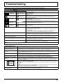
Troubleshooting ..................................................... 45
List of Aspect Modes ............................................. 46
Remote Control Operation / Code List ................ 47
Applicable Input Signals ........................................ 49
Specifications ......................................................... 51
Trademark Credits
• VGA is a trademark of International Business Machines Corporation.
• Macintosh is a registered trademark of Apple Computer, USA.
• SVGA, XGA, SXGA and UXGA are registered trademarks of the video Electronics Standard Association.
Even if no special notation has been made of company or product trademarks, these trademarks have been fully respected.
• HDMI, the HDMI logo and High-Definition Multimedia Interface are trademarks or registered trademarks of HDMI
Licensing LLC.
Note:
Do not allow a still picture to be displayed for an extended period, as this can cause a permanent image
retention to remain on the Plasma Display.
Examples of still pictures include logos, video games, computer images, teletext and images displayed in 4:3 mode.
2
Important Safety Notice
WARNING
1) To prevent damage which may result in fire or shock hazard, do not expose this appliance to dripping
or splashing.
Do not place containers with water (flower vase, cups, cosmetics, etc.) above the set. (including on
shelves above, etc.)
No naked flame sources, such as lighted candles, should be placed on / above the set.
2) To prevent electric shock, do not remove cover. No user serviceable parts inside. Refer servicing to qualified
service personnel.
3) Do not remove the earthing pin on the power plug. This apparatus is equipped with a three pin earthing-type
power plug. This plug will only fit an earthing-type power outlet. This is a safety feature. If you are unable to
insert the plug into the outlet, contact an electrician.
Do not defeat the purpose of the earthing plug.
4) To prevent electric shock, ensure the earthing pin on the AC cord power plug is securely connected.
CAUTION
This appliance is intended for use in environments which are relatively free of electromagnetic fields.
Using this appliance near sources of strong electromagnetic fields or where electrical noise may overlap with
the input signals could cause the picture and sound to wobble or cause interference such as noise to appear.
To avoid the possibility of harm to this appliance, keep it away from sources of strong electromagnetic fields.
IMPORTANT: THE MOULDED PLUG
FOR YOUR SAFETY, PLEASE READ THE FOLLOWING TEXT CAREFULLY.
This display is supplied with a moulded three pin mains plug for your safety and convenience. A 10 amp fuse is
fitted in this plug. Shall the fuse need to be replaced, please ensure that the replacement fuse has a rating of 10
amps and that it is approved by ASTA or BSI to BS1362.
Check for the ASTA mark
ASA
or the BSI mark
on the body of the fuse.
If the plug contains a removable fuse cover, you must ensure that it is refitted when the fuse is replaced.
If you lose the fuse cover the plug must not be used until a replacement cover is obtained.
A replacement fuse cover can be purchased from your local Panasonic dealer.
Do not cut off the mains plug.
Do not use any other type of mains lead except the one supplied with this display.
The supplied mains lead and moulded plug are designed to be used with this display to
avoid interference and for your safety.
If the socket outlet in your home is not suitable, get it changed by a qualified electrician.
If the plug or mains lead becomes damaged, purchase a replacement from an authorized dealer.
WARNING : — THIS DISPLAY MUST BE EARTHED.
How to replace the fuse. Open the fuse compartment with a screwdriver and replace the fuse.
3
Safety Precautions
WARNING
Setup
This Plasma Display is for use only with the following optional accessories. Use with any other type of
optional accessories may cause instability which could result in the possibility of injury.
(All of the following accessories are manufactured by Panasonic Corporation.)
• Pedestal ................................................................................TY-ST50VX100 (for TH-50VX100E),
TY-ST65VX100 (for TH-65VX100E)
• Wall-hanging bracket (vertical)..............................................TY-WK42PV7 (for TH-50VX100E),
TY-WK65PV7 (for TH-65VX100E)
• Wall-hanging bracket (angled) ..............................................TY-WK42PR7 (for TH-50VX100E),
TY-WK65PR8 (for TH-65VX100E)
• BNC Component Video Terminal Board ...............................TY-42TM6A
• RCA Component Video Terminal Board ................................TY-42TM6Z
• HD-SDI Terminal Board ........................................................TY-FB9HD
• HD-SDI Terminal Board with audio .......................................TY-FB10HD
• Dual Link HD-SDI Terminal Board ........................................TY-FB11DHD
• Dual HDMI Terminal Board ...................................................TY-FB10HMD
• Ir Through Terminal Board ....................................................TY-FB9RT
• DVI-D Terminal Board ...........................................................TY-FB11DD
Always be sure to ask a qualified technician to carry out set-up.
Small parts can present choking hazard if accidentally swallowed. Keep small parts away from young children.
Discard unneeded small parts and other objects, including packaging materials and plastic bags/sheets to prevent
them from being played with by young children, creating the potential risk of suffocation.
Do not place the Plasma Display on sloped or unstable surfaces.
• The Plasma Display may fall off or tip over.
Do not place any objects on top of the Plasma Display.
• If water is spills onto the Plasma Display or foreign objects get inside it, a short-circuit may occur which could result in
fire or electric shock. If any foreign objects get inside the Plasma Display, please consult your local Panasonic dealer.
Transport only in upright position!
• Transporting the unit with its display panel facing upright or downward may cause damage to the internal circuitry.
Ventilation should not be impeded by covering the ventilation openings with items such as newspapers,
table cloths and curtains.
For sufficient ventilation;
If using the pedestal (optional accessory), leave a space of 10 cm or more at the top, left and right, and 7 cm
or more at the rear, and also keep the space between the bottom of the display and the floor surface.
If using some other setting-up method, follow the manual of it. (If there is no specific indication of
installation dimension in the installation manual, leave a space of 10 cm or more at the top, bottom, left and
right, and 7 cm or more at the rear.)
4
Safety Precautions
When using the Plasma Display
The Plasma Display is designed to operate on 220 - 240 V AC, 50/60 Hz.
Do not cover the ventilation holes.
• Doing so may cause the Plasma Display to overheat, which can cause fire or damage to the Plasma Display.
Do not stick any foreign objects into the Plasma Display.
• Do not insert any metal or flammable objects into the ventilations holes or drop them onto the Plasma Display, as
doing so can cause fire or electric shock.
Do not remove the cover or modify it in any way.
• High voltages which can cause severe electric shocks are present inside the Plasma Display. For any inspection,
adjustment and repair work, please contact your local Panasonic dealer.
Ensure that the mains plug is easily accessible.
An apparatus with CLASS I construction shall be connected to a mains socket outlet with a protective earthing connection.
Do not use any power supply cord other than that provided with this unit.
• Doing so may cause fire or electric shocks.
Securely insert the power supply plug as far as it will go.
• If the plug is not fully inserted, heat may be generated which could cause fire. If the plug is damaged or the wall
socket is loose, they shall not be used.
Do not handle the power supply plug with wet hands.
• Doing so may cause electric shocks.
Do not do anything that may damage the power cable. When disconnecting the power cable, pull on the plug body, not the cable.
• Do not damage the cable, make any modifications to it, place heavy objects on top of it, heat it, place it near any
hot objects, twist it, bend it excessively or pull it. To do so may cause fire and electric shock. If the power cable is
damaged, have it repaired at your local Panasonic dealer.
If the Plasma Display is not going to be used for any prolonged length of time, unplug the power supply
plug from the wall outlet.
If problems occur during use
If a problem occurs (such as no picture or no sound), or if smoke or an abnormal odour starts to come out
from the Plasma Display, immediately unplug the power supply plug from the wall outlet.
• If you continue to use the Plasma Display in this condition, fire or electric shock could result. After checking
that the smoke has stopped, contact your local Panasonic dealer so that the necessary repairs can be made.
Repairing the Plasma Display yourself is extremely dangerous, and shall never be done.
If water or foreign objects get inside the Plasma Display, if the Plasma Display is dropped, or if the cabinet
becomes damages, disconnect the power supply plug immediately.
• A short circuit may occur, which could cause fire. Contact your local Panasonic dealer for any repairs that need to be made.
5
Safety Precautions
CAUTION
When using the Plasma Display
Do not bring your hands, face or objects close to the ventilation holes of the Plasma Display.
• Heated air comes out from the ventilation holes at the top of Plasma Display will be hot. Do not bring your hands
or face, or objects which cannot withstand heat, close to this port, otherwise burns or deformation could result.
Be sure to disconnect all cables before moving the Plasma Display.
• If the Plasma Display is moved while some of the cables are still connected, the cables may become damaged,
and fire or electric shock could result.
Disconnect the power supply plug from the wall socket as a safety precaution before carrying out any
cleaning.
• Electric shocks can result if this is not done.
Clean the power cable regularly to prevent it becoming dusty.
• If dust built up on the power cord plug, the resultant humidity can damage the insulation, which could result in
fire. Pull the power cord plug out from the wall outlet and wipe the mains lead with a dry cloth.
Do not burn or breakup batteries.
• Batteries must not be exposed to excessive heat such as sunshine, fire or the like.
This Plasma Display radiates infrared rays, therefore it may affect other infrared communication equipment.
Install your infrared sensor in a place away from direct or reflected light from your Plasma Display.
Cleaning and maintenance
The front of the display panel has been specially treated. Wipe the panel surface gently using only a
cleaning cloth or a soft, lint-free cloth.
• If the surface is particularly dirty, wipe with a soft, lint-free cloth which has been soaked in pure water or water in
which neutral detergent has been diluted 100 times, and then wipe it evenly with a dry cloth of the same type until
the surface is dry.
• Do not scratch or hit the surface of the panel with fingernails or other hard objects, otherwise the surface may
become damaged. Furthermore, avoid contact with volatile substances such as insect sprays, solvents and
thinner, otherwise the quality of the surface may be adversely affected.
If the cabinet becomes dirty, wipe it with a soft, dry cloth.
• If the cabinet is particularly dirty, soak the cloth in water to which a small amount of neutral detergent has been
added and then wring the cloth dry. Use this cloth to wipe the cabinet, and then wipe it dry with a dry cloth.
• Do not allow any detergent to come into direct contact with the surface of the Plasma Display. If water droplets
get inside the unit, operating problems may result.
• Avoid contact with volatile substances such as insect sprays, solvents and thinner, otherwise the quality of the
cabinet surface may be adversely affected or the coating may peel off. Furthermore, do not leave it for long
periods in contact with articles made from rubber or PVC.
6
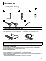
Accessories
Accessories Supply
Check that you have the accessories and items shown
Operating Instruction book
Remote Control
Transmitter
N2QAYB000323
Batteries for the Remote
Control Transmitter
(2 × R6 (UM3) Size)
POS.
/SIZE PICTURE
DISPLAY
FUNCTION
PC
COMPO.
HDMI
フ
CH INPUT
VIDEO
MENU
EXT.SCALER
OFF TIMER
MEM.
LOAD
DISPLAY
Power supply cord
Fixing band × 1
Remote Control Batteries
Requires two R6 batteries.
1. Pull and hold the hook, then open the battery cover.
2. Insert batteries - note correct polarity ( + and -).
Open
Hook
Close
“R6 (UM3)” size
Helpful Hint:
For frequent remote control users, replace old batteries with Alkaline batteries for longer life.
Precaution on battery use
Incorrect installation can cause battery leakage and corrosion that will damage the remote control transmitter.
Disposal of batteries should be in an environment-friendly manner.
Observe the following precaution:
1. Batteries shall always be replaced as a pair. Always use new batteries when replacing the old set.
2. Do not combine a used battery with a new one.
3. Do not mix battery types (example: “Zinc Carbon” with “Alkaline”).
4. Do not attempt to charge, short-circuit, disassemble, heat or burn used batteries.
5. Battery replacement is necessary when remote control acts sporadically or stops operating the Plasma Display set.
6. Do not burn or breakup batteries.
Batteries must not be exposed to excessive heat such as sunshine, fire or the like.
7. Make a note of the remote control codes before changing batteries in case the codes are reset. (see page 43)
7
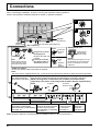
Connections
When connecting the speakers, be sure to use only the optional accessory speakers.
Refer to the speaker’s Installation Manual for details on speaker installation.
1
2
Speaker
terminal (L)
Speaker
terminal (R)
2
AC cord connection (see page 12)
– AC cord fixing
Unplug the AC cord
Close
1
Push until
the hook
clicks.
1 Plug the AC cord into
the display unit.
Plug the AC cord until
it clicks.
2
Note:
Make sure that the AC
cord is locked on both
the left and right sides.
Unplug the AC
cord pressing
the two knobs.
Open
Note:
When disconnecting the AC cord,
be absolutely sure to disconnect
the AC cord plug at the socket
outlet first.
2. Pull
off.
2 Fix the AC cord with
the clamper which is
attached to the unit.
1
1. Keep the
knob
pressed.
– Cable fixing band
Secure any excess cables with band as required.
Note:
One fixing band is supplied with this unit. In case of securing cables at two positions, please purchase it separately.
Pass the attached cable
To secure cables connected to Terminals, wrap the cable fixing band around them
fixing band through the
then pass the pointed end through the locking block, as shown in the figure.
clip as shown in the figure. While ensuring there is sufficient slack in cables to minimize stress
(especially in the power cord), firmly bind all cables with the supplied fixing
band.
To tighten:
To loosen:
Push the catch
Pull
2
1
Pull
R AUDIO
L
PR/CR/R PB/CB/B
Y/G
AUDIO
COMPONENT/RGB IN
SLOT1
Dual HDMI Terminals
(equivalent of Dual HDMI
Terminal Board (TY-FB10HMD))
(see page 11)
SLOT2
SLOT3
COMPONENT/RGB IN and
Audio IN Terminals (equivalent
of RCA Component Video
Terminal Board (TY-42TM6Z))
(see page 11)
PC
IN
From EXTERNAL
monitor terminal
on Computer
(see page 9)
Note: At factory shipment, Terminal boards are installed in SLOT 1, SLOT 2 and SLOT 3.
8
SERIAL
From SERIAL
Terminal on
Computer
(see page 10)
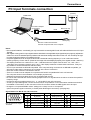
Connections
PC Input Terminals connection
(Female)
COMPUTER
AUDIO
PC IN
Conversion adapter
(if necessary)
RGB
Mini D-sub 15p
PC cable
Audio
(Male)
Stereo plug
Connect a cable which matches
the audio output terminal on the computer.
Notes:
• Due to space limitations, occasionally you may have trouble connecting Mini D-sub 15P cable with ferrite core to PC input
Terminal.
• With regard to the typical PC input signals that are described in the applicable input signals list (see page 49), adjustment
values such as for the standard picture positions and sizes have already been stored in this unit. You can add up to eight
PC input signal types that are not included in the list.
• Computer signals which can be input are those with a horizontal scanning frequency of 15 to 110 kHz and vertical
scanning frequency of 48 to 120 Hz. (However, the image will not be displayed properly if the signals exceed 1,200 lines.)
• The display resolution is a maximum of 1,440 × 1,080 dots when the aspect mode is set to “4:3”, and 1,920 ×
1,080 dots when the aspect mode is set to “16:9”. If the display resolution exceeds these maximums, it may not
be possible to show fine detail with sufficient clarity.
• The PC input terminals are DDC2B-compatible. If the computer being connected is not DDC2B-compatible, you
will need to make setting changes to the computer at the time of connection.
• Some PC models cannot be connected to the set.
• There is no need to use an adapter for computers with DOS/V compatible Mini D-sub 15P terminal.
• The computer shown in the illustration is for example purposes only.
• Additional equipment and cables shown are not supplied with this set.
• Do not set the horizontal and vertical scanning frequencies for PC signals which are above or below the specified
frequency range.
• Component Input is possible with the pin 1, 2, 3 of the Mini D-sub 15P Connector.
• To use sync input VBS signals, use the connector which incorporates a 75-ohm termination resistance and which
is available on the market, for the connection of the HD connector where the VBS signals are to be input.
• Change the “Component/RGB-in select” setting in the “Setup” menu to “Component”
(when Component signal connection) or “RGB” (when RGB signal connection). (see page 38)
Signal Names for Mini D-sub 15P Connector
5
4
10 9
3
2
8
1
7
6
15 14 13 12 11
Pin Layout for PC Input
Terminal
Pin No.
Signal Name
Pin No.
Signal Name
Pin No.
Signal Name
1
R (PR/CR)
6
GND (Ground)
11
NC (not connected)
2
G (Y)
7
GND (Ground)
12
SDA
3
B (PB/CB)
8
GND (Ground)
13
HD/SYNC
4
NC (not connected)
9
+5 V DC
14
VD
5
GND (Ground)
10
GND (Ground)
15
SCL
9
Connections
SERIAL Terminals connection
The SERIAL terminal is used when the Plasma Display is controlled by a computer.
(Male)
COMPUTER
1
2
6
3
7
4
8
5
9
SERIAL
RS-232C Straight cable
Pin layout for SERIAL Terminal
(Female)
D-sub 9p
Notes:
• Use the RS-232C straight cable to connect the computer to the Plasma Display.
• The computer shown is for example purposes only.
• Additional equipment and cables shown are not supplied with this set.
The SERIAL terminal conforms to the RS-232C
interface specification, so that the Plasma Display can
be controlled by a computer which is connected to this
terminal.
The computer will require software which allows the
sending and receiving of control data which satisfies
the conditions given below. Use a computer application
such as programming language software. Refer to the
documentation for the computer application for details.
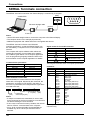
Communication parameters
Signal level
Synchronization method
Baud rate
Parity
Character length
Stop bit
Flow control
RS-232C compliant
Asynchronous
9600 bps
None
8 bits
1 bit
-
Basic format for control data
The transmission of control data from the computer
starts with a STX signal, followed by the command, the
parameters, and lastly an ETX signal in that order. If
there are no parameters, then the parameter signal does
not need to be sent.
STX
C1 C2 C3
Start
(02h)
:
P1 P2 P3 P4 P5
ETX
Colon
Parameter(s)
(1 - 5 bytes)
3-character
command (3 bytes)
End
(03h)
Notes:
• If multiple commands are transmitted, be sure to wait
for the response for the first command to come from this
unit before sending the next command.
• If an incorrect command is sent by mistake, this unit will
send an “ER401” command back to the computer.
• SL1A, SL1B, SL2A and SL2B of Command IMS are
available only when a dual input terminal board is
attached.
10
Signal names for D-sub 9P connector
Pin No.
2
3
5
4 • 6
7
8
1 • 9
Details
RXD
TXD
GND
Non use
(Shorted in this set)
NC
These signal names are those of computer specifications.
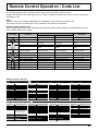
Command
Command
PON
POF
AVL
IMS
DAM
Parameter
None
None
**
None
SL1
SL2
SL3
PC1
SL1A
SL1B
SL2A
SL2B
None
ZOOM
FULL
JUST
NORM
ZOM2
ZOM3
SJST
SNOM
SFUL
14:9
Control details
Power ON
Power OFF
Volume 00 - 63
Input select (toggle)
Slot1 input
Slot2 input
Slot3 input
PC input
Slot1 input (INPUT1A)
Slot1 input (INPUT1B)
Slot2 input (INPUT2A)
Slot2 input (INPUT2B)
Screen mode select (toggle)
Zoom1
16:9
Just
4:3
Zoom2
Zoom3
Just
4:3
4:3 Full
14:9
With the power off, this display responds to PON
command only.
Connections
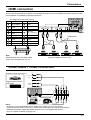
HDMI connection
This unit has terminal boards equivalent to Dual HDMI Terminal Board (TY-FB10HMD) and RCA Component Video
Terminal Board (TY-42TM6Z) as standard equipment.
[Pin assignments and signal names]
Pin No.
1
2
3
4
5
6
7
8
9
10
Signal
T.M.D.S Data2+
T.M.D.S Data2
Shield
T.M.D.S Data2T.M.D.S Data1+
T.M.D.S Data1
Shield
T.M.D.S Data1T.M.D.S Data0+
T.M.D.S Data0
Shield
T.M.D.S Data0T.M.D.S Clock+
19
Pin No.
Signal
T.M.D.S Clock
Shield
11
12
T.M.D.S Clock-
13
CEC
14
Reserved
(N.C. on device)
15
16
R AUDIO
SLOT1
SCL
SDA
DDC/CEC
Ground
+5V Power
Hot Plug Detect
17
18
19
SLOT2
PR/CR/R PB/CB/B
Y/G
PC
SLOT3
I
HDMI cables
HDMI cables
3 1
HDMI
AV OUT
18
L
COMPONENT/RGB IN
HDMI
AV OUT
HDMI
AV OUT
HDMI
AV OUT
4 2
DVD Player or SET-TOP-BOX
(HDMI compatible machines only)
Note:
Additional equipment and HDMI cables
shown are not supplied with this set.
COMPONENT / RGB connection
COMPONENT VIDEO OUT
PR
Example of input signal source
DVD
Digital TV-SET-TOP-BOX
(DTV-STB)
Y, PB, PR,
OUT
PB
Y
L
AUDIO
R
OUT
R AUDIO
L
PR/CR/R PB/CB/B
Y/G
COMPONENT/RGB IN
SLOT3
Computer
RGB Camcorder
or
Notes:
• Change the “Component/RGB-in select” setting in the “Setup” menu to “Component”
(when Component signal connection) or “RGB” (when RGB signal connection). (see page 38)
• Additional equipment, cables and adapter plugs shown are not supplied with this set.
• Sync on G signal is needed. (see page 40)
11
Power On / Off
Connecting the AC cord plug to the Plasma
Display.
Fix the AC cord plug securely to the Plasma
Display with the clamper. (see page 8)
Connecting the plug to the Wall Outlet.
Notes:
• Main plug types vary between countries. The
power plug shown at right may, therefore, not be
the type fitted to your set.
• When disconnecting the AC cord, be absolutely
sure to disconnect the AC cord plug at the socket
outlet first.
INPUT
MENU
OK
Power
Indicator
Press the Power switch on the Plasma Display to
turn the set on: Power-On.
INPUT
Remote Control
Sensor
MENU
Power Indicator: Green
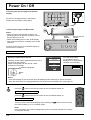
When first switching on the unit
Following screen will be displayed when the unit is
turned on for the first time.
Select the language with the remote control.
Unit buttons are invalid.
1
Select the language.
2
Set.
OSD Language
English (UK)
Deutsch
Français
From the second time
on, the below screen is
displayed for a while (setting
condition is an example).
Italiano
Español
PC
ENGLISH (US)
1 6 :9
Notes:
• Once the language is set, the screen won’t be displayed when switching on the unit next time.
• From the second time on, language selection can be done from the Setup menu. (see page 13)
Press the
button on the remote control to turn the Plasma Display off.
Power Indicator: Red (standby)
Press the
button on the remote control to turn the Plasma Display on.
Power Indicator: Green
HDMI
Turn the power to the Plasma Display off by pressing the
the Plasma Display is on or in standby mode.
switch on the unit, when
Note:
During operation of the power management function, the power indicator turns orange
in the power off state.
12
Initial selections
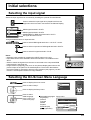
Selecting the input signal
Select the input signals to be connected by installing the optional Terminal Boards.
INPUT
Press to select the input signal to be played back from the
equipment which has been connected to the Plasma Display.
PC
COMPO.
INPUT
HDMI
HDMI1
HDMI2
HDMI3
HDMI4
COMPONENT
PC
フ
HDMI signal terminal in SLOT1
CH INPUT
HDMI signal terminal in SLOT2
COMPONENT or RGB signal terminal in SLOT3
PC signal terminal in PC IN
Using dedicated buttons for input selection
Press to select HDMI signal terminals 1–4 in SLOT 1 and 2.
Press to select component or RGB signal terminal in SLOT 3.
DISPLAY
Press to select PC signal terminal in PC IN.
Notes:
• Selecting is also possible by pressing the INPUT button on the unit.
• Input terminal will not be selected if the terminal board is not installed into the
SLOT.
• Select to match the signals from the source connected to the component/RGB
input terminals. (see page 38)
• Image retention (image lag) may occur on the plasma display panel when a still
picture is kept on the panel for an extended period. The function that darkens
the screen slightly is activated to prevent image retention (see page 45), but this
function is not the perfect solution to image retention.
INPUT
ENTER/■
MENU
INPUT
ENTER/■
MENU
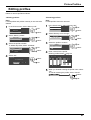
Selecting the On-Screen Menu Language
Press to display the menu screen.
Picture
Setup
Press to select “Setup”.
Pos. /Size
Sound
Press to display the Setup menu.
HDMI
Press to select
OSD Language.
Press to select your
preferred language.
Selectable languages
English(UK)
Deutsch
Français
Italiano
Español
ENGLISH(US)
(Japanese)
Setup menu
Signal
Screensaver
Component/RGB-in select
RGB
External scaler mode
Off
POWER SAVE
OFF
OSD position
OSD Language
Upper left
English (UK)
13
Basic Controls
Main Unit
INPUT button
(INPUT1, INPUT2,
INPUT3 and PC
selection)
(see page 13)
When the menu screen is displayed:
“▲” : press to move the cursor up
“▼” : press to move the cursor
down (see page 18)
Remote control
sensor
INPUT
Main Power On / Off Switch
MENU Screen ON / OFF
Each time the MENU button is pressed, the menu
screen will switch. (see page 18)
14
MENU
ENTER/■
Enter / Aspect
button
(see page 17, 18)
Power Indicator
The Power Indicator will light.
• Power-OFF...... Indicator not illuminated (The
unit will still consume some
power as long as the power
cord is still inserted into the
wall outlet.)
• Standby .......... Red
• Power-ON ....... Green
• DPMS .............. Orange (With PC input signal
and during operation of PC’s
screensaver.)
Basic Controls
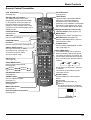
Remote Control Transmitter
POS. /SIZE button
(see page 30)
PICTURE button
(see page 20)
Standby (ON / OFF) button
The Plasma Display must first be
plugged into the wall outlet and turned
on at the power switch (see page 12).
Press this button to turn the Plasma
Display On, from Standby mode. Press
it again to turn the Plasma Display Off to
Standby mode.
LIGHT button
Lights the INPUT and VIDEO MENU
buttons for 5 seconds. Makes the
selected remote control mode key
(DISPLAY, VCR, DBS/CBL or DVD) flash
three times. Press again to turn off the
INPUT and VIDEO MENU button lights.
FUNCTION button
(see page 16)
OK button
Press to make selections.
POS.
/SIZE PICTURE
DISPLAY
Equipment (Remote control mode)
selection buttons (see page 42, 43)
FUNCTION
MENU button
Displays menu screen. (see page 18)
PC
COMPO.
POSITION buttons
HDMI
フ
PC button
Press to select PC input. (see page 13)
DIRECT INPUT buttons
Press the each button to select
the INPUT mode. (see page 13)
This button is used to switch
directly to INPUT mode.
CH INPUT
VIDEO
MENU
EXT.SCALER
OFF TIMER
INPUT button
(see page 13)
VIDEO MENU button
Press to select Picture Mode.
(see page 20)
Normal
Dynamic
Monitor
Cinema
External equipment operations
(see page 42)
OFF TIMER button
The Plasma Display can be preset to
switch to stand-by after a fixed period.
The setting changes to 30 minutes, 60
minutes, 90 minutes and 0 minutes (off
timer cancelled) each time the button is
pressed.
60
90
0
When three minutes remain, “Off timer
3” will flash.
The off timer is cancelled if a power
interruption occurs.
MEM.
LOAD
ASPECT button
Press to adjust the aspect.
(see page 17)
MEM. LOAD button
(see page 26)
COMPO. button
Press to select COMPONENT or RGB
input. (see page 13)
30
EXT.SCALER button
(see page 16)
Numeric buttons
(see page 26)
RETURN button (see page 18)
Press the RETURN button to return to
previous menu screen.
DISPLAY
RECALL button
Press to display the current system
status.
1 Input label
2 Aspect mode (see page 17)
3 Off timer
The off timer indicator is displayed
only when the off timer has been set.
1
PC
4:3
Off timer
2
90
3
15
Basic Controls
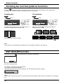
Scrolling bar and Test patterns functions
Pressing
activates one of the following two functions. The function button setting can be configured by
accessing “Function button assign” in the Options menu. (see page 41)
Scrolling bar
Test patterns
Press
Press
Press to
select
“Yes”.
Scrolling bar
Scrolling bar
Yes
No
Test patterns
Yes
Press.
Activates the Scrolling bar only screensaver. After 15
minutes, the display enters standby mode.
No
Press.
Each time you press
a different test pattern is
displayed (seven in all).
Colour Bars
Scrolling bar only
Press to
select
“Yes”.
Test patterns
Black
Red
Green
Frame
1% window (2 lines × 2 dots)
Blue
To exit this mode, press any button.
To exit this mode, press any button other than
.
Note:
Auto power off is deactivated during Scrolling bar or Test patterns operation. (see page 36)
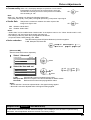
EXT. SCALER function
Each time you press
External scaler mode
, an external scaler is activated or deactivated.
On
Off: Use the built-in scaler.
On: Use an external scaler.
The setting is valid with the following signals.
1125 (1080) / 24p•25p•30p•50p•60p
With input signals other than these, specifying “On” will display the following message.
Input signal must be 1125p(1080p)
External scaler mode
On
Note:
You can also turn the built-in scaler On and Off by accessing “External scaler mode” in the Setup menu. (see page
35)
16
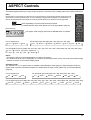
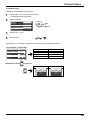
ASPECT Controls
The Plasma Display will allow you to enjoy viewing the picture at its maximum size, including wide screen cinema format picture.
Note:
Be aware that if you put the display in a public place for commercial purposes or a public showing and then use the aspect mode
select function to shrink or expand the picture, you may be violating the copyright under copyright law. It is prohibited to show or
alter the copyrighted materials of other people for commercial purposes without the prior permission of the copyright holder.
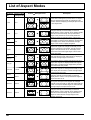
Press repeatedly to move through the aspect options:
For details about the aspect mode, please see “List of Aspect Modes” (page 46).
HDMI
[from the unit]
The aspect mode changes each time the ENTER button is pressed.
INPUT
ENTER/■
MENU
For PC signal input:
4:3
Zoom
16:9
For SD signal input (525 (480) / 60i • 60p, 625 (575) / 50i • 50p):
4:3
Zoom1
Zoom2
Zoom3
16:9
14:9
Just
For HD signal input [1125 (1080) / 60i • 50i • 60p • 50p • 24p • 25p • 30p • 24sF, 1250 (1080) / 50i, 750 (720) / 60p • 50p]:
4:3
Just
4:3 Full
14:9
Zoom1
16:9
Zoom2
Zoom3
Notes:
• The aspect mode is memorized separately for each input terminal.
• Do not allow the picture to be displayed in 4:3 mode for an extended period, as this can cause a permanent image
retention to remain on the Plasma Display Panel.
All Aspect mode
Set “All Aspect” to “On” in Options menu to enable the extended aspect mode (page 41). When All Aspect mode, the
aspect mode of pictures is switched as follows. For details about the aspect mode, please see “List of Aspect Modes”
(page 46)
For PC signal input:
4:3
Zoom
16:9
For SD signal input (525 (480) / 60i • 60p, 625 (575) / 50i • 50p):
4:3
Zoom1
Zoom2
Zoom3
16:9
14:9
Just
For HD signal input [1125 (1080) / 60i • 50i • 60p • 50p • 24p • 25p • 30p • 24sF, 1250 (1080) / 50i, 750 (720) / 60p • 50p]:
4:3 Full
Zoom1
Zoom2
Zoom3
16:9
14:9
Just1
Just2
4:3 (1)
4:3 (2)
17
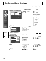
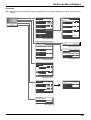
On-Screen Menu Displays
Various menus allow you to make settings for the picture, sound, and other functions so that you can enjoy watching Display
best suited for you.
POS.
/SIZE PICTURE
1
Display the menu screen.
Picture
Unit
press
Normalise
Setup
Picture Mode
Pos. /Size
Contrast
25
Sound
Brightness
0
Sharpness
5
Options
Remote Control
White balance
Each time the MENU
button is pressed, the
menu screen will switch.
Normal
Colour Management
press several
times
MENU
Normal
Off
Advanced settings
HDMI
Memory save
Memory load
Normal Viewing
Memory edit
Picture
Setup
Pos. /Size
Sound
DISPLAY
2
Select the menu.
Picture
1
select
2
press
Setup
Pos. /Size
Sound
Options
Press to
return to the
previous
menu.
(Example: Sound menu)
Menus can also be accessed directly by pressing dedicated buttons, such as
(see page 20, 30)
3
and
.
Select the item.
Normalise
Sound Mode
Normal
Bass
0
Mid
0
Treble
0
Balance
0
Surround
Volume
select
select
press
ENTER/■
Off
1
(Example: Sound menu)
4
Set.
set
set
press
ENTER/■
5
18
Exit the menu.
press
MENU
press several
times
On-Screen Menu Displays
Overview
Note: Menu that cannot be adjusted is grayout. Adjustable menu changes depending on signal, input and menu
setting.
Picture
Normalise
Advanced settings
Setup
Picture Mode
Pos. /Size
Contrast
25
Black extension
0
Sound
Brightness
0
Input level
0
Colour
6
Gamma
Hue
0
AGC
Sharpness
5
W/B High R
0
Normal
W/B High G
0
Off
W/B High B
0
W/B Low R
0
W/B Low G
0
W/B Low B
0
Options
Normal
White balance
Colour Management
Advanced settings
Normalise
2.2
Off
Memory save
Cinema reality
Off
Memory load
Studio Gain
Off
Memory edit
Noise reduction
Off
see page 20-29
Signal
see page 22, 23
[ Component ]
Signal
XGA Mode
Screensaver
1024 ×768
Component/RGB-in select
see page 39, 40
RGB
Off
External scaler mode
Power save
Off
Standby save
On
Power management
Off
Auto power off
Off
OSD design
Type1
OSD position
Upper left
OSD Language
English (UK)
Screensaver
Start
Function
Negative image
Side panel
High
Wobbling
Off
Peak limit
Off
see page 33, 34
see page 33-40
Normalise
Auto Setup
H-Pos
0
H-Size
0
V-Pos
0
V-Size
0
Dot Clock
0
Clock Phase
-16
1:1 Pixel Mode
Off
Display size
Off
see page 30, 31
SDI Sound Output
Normalise
Sound Mode
Normal
2/2
Left Channel
Channel 1
Channel 2
Bass
0
Right Channel
Mid
0
Sound Out
On
Treble
0
Level Meter
Off
Balance
0
Surround
Volume
Off
see page 32
1
see page 32
Onscreen display
On
All Aspect
Off
Studio mode
Function button assign
Off
Scrolling bar
Memory lock
see page 41
19
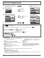
Picture Adjustments
1
2
Display the menu screen.
During “RGB” and “PC” input
signal.
Select “Picture”.
Normalise
Picture
Picture Mode
OK
2
Normal
Contrast
25
Setup
Brightness
0
Pos. /Size
Sharpness
5
select
1
Sound
White balance
Normal
Colour Management
Off
Advanced settings
3
Select the item and set.
During “Digital” and
“Component” input signal.
Normalise
Picture Mode
25
Brightness
0
Sharpness
5
White balance
adjust or select
2
Normal
Contrast
select
1
Normal
Colour Management
Off
Advanced settings
4
Normal
Contrast
25
Brightness
0
Colour
6
Hue
0
Sharpness
5
White balance
Exit the menu.
Using
Normalise
Picture Mode
Normal
Colour Management
or
Off
Advanced settings
for menu display
To display a menu for adjustment of the Picture menu on the bottom of the screen, press
Contrast
25
2
adjust or select
1
select
To display a menu for Advanced settings adjustment, press
Black extension
.
again.
0
To hide the menu, press
or
.
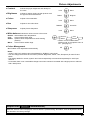
● Picture Mode
You can switch to the optimal picture mode for the video
source and viewing environment.
Normal:
For viewing in standard (evening lighting)
environments. This menu selects the normal levels of
Brightness and Contrast.
Dynamic:
For viewing in brighter environments.
This menu selects higher than normal levels of
Brightness and Contrast.
Normal
Monitor
Dynamic
Cinema
Cinema:
Ideal for movies.
Monitor:
For use when creating broadcast or movie content.
With this picture, even if the overall average picture
level (APL) changes, the brightness of areas with the
same signal level does not change.
Notes:
• When “Monitor” is selected in Picture Mode, the following menu items cannot be set.
Picture menu: Contrast
Screensaver menu: Peak limit (see page 34)
Setup menu: Power save (see page 36)
• If you would like to change the picture and colour of the selected Picture menu to something else, adjust using
the items in the Picture menu. (see next page)
20
Picture Adjustments
● Contrast
Selects the proper brightness and density for
the room.
● Brightness
Adjusts for easier viewing of dark pictures such
as night scenes and black hair.
● Colour
Less
Darker
More
Adjusts for nice skin colour.
Reddish
● Sharpness
Brighter
Adjusts colour saturation.
Less
● Hue
More
Greenish
Adjusts picture sharpness.
Less
More
● White balance Switches to various screen colour tones.
Normal: Intermediate colour temperature.
Cool:
Colours with a bluish tinge.
Studio: Optimal colour temperature for studio viewing
(3200 K).
Warm: Colours with a reddish tinge.
● Colour Management
On: Enables colour adjustment automatically.
Cool
Normal
Warm
Studio*
* “Studio” can be modified when
“Studio mode” in the Options menu is
“On”. (see page 41)
Off
On
Notes:
• “Colour” and “Hue” settings cannot be adjusted for “RGB/PC” input signal.
• You can change the level of each function (Contrast, Brightness, Colour, Hue, Sharpness) for each Picture
Mode.
• The setting details for normal, dynamic and cinema respectively are memorized separately for each input
terminal.
• In Contrast, there is not a noticeable change even when contrast is increased with a bright picture or reduced
with a dark picture.
Helpful Hint (
Normalise
Normalization)
While the “Picture” menu is displayed, if the OK button is pressed during “Normalise”, then all adjustment values
are returned to the factory settings.
21
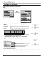
Picture Adjustments
Advanced settings
Enables fine picture adjustment at a professional level.
Notes:
• The adjustment values are memorized separately for each input terminal.
• The adjustment range values should be used as an adjustment reference.
Advanced settings
Normalise
Picture Mode
Normalise
Normal
Contrast
25
Black extension
0
Brightness
0
Input level
0
Sharpness
5
Gamma
White balance
Colour Management
2.2
Off
AGC
Normal
Off
Advanced settings
W/B High R
0
W/B High G
0
W/B High B
0
W/B Low R
0
W/B Low G
0
W/B Low B
0
Cinema reality
Off
Studio Gain
Off
Noise reduction
Off
● Black
extension
Adjusts the dark shades of the image in gradation.
● Input level
Adjustment of parts which are extremely bright and hard to
see.
● Gamma
Picture Mode
Normal
Dynamic
Cinema
Monitor
Less
More
Less
More
Available setting values vary depending on “Picture Mode”
settings and the type of input signal, as follows.
S Curve 1.0 2.0 2.2 2.5 2.6
–
–
–
*3
*3
*3
*3
–
*2
–
*1
*1
Down
Up
Off
On
*1 When 2k1k signals are received with the Dual Link HD-SDI Terminal Board
(TY-FB11DHD), Gamma “2.6” can also be selected.
*2 When 60 Hz signals are received, Gamma “2.5” can also be selected.
*3 When 2k1k signals are received with the Dual Link HD-SDI Terminal Board
(TY-FB11DHD), Gamma “1.0” cannot be selected.
● AGC
Increases the brightness of dark signal automatically.
● “W/B” adjustment
W/B High R
0
W/B High G
0
W/B High B
0
W/B Low R
0
W/B Low G
0
W/B Low B
0
Adjusts the white balance for light red, light
green or light blue areas.
Less
More
Adjusts the white balance for dark red,
dark green or dark blue areas.
Carry out “W/B” adjustment as follows.
1. Adjust the white balance of the bright sections using the “W/B High R”, “W/B High G” and “W/B High B” settings.
2. Adjust the white balance of the dark sections using the “W/B Low R”, “W/B Low G” and “W/B Low B” settings.
3. Repeat steps 1 and 2 to adjust.
Steps 1 and 2 affect each other’s settings, so repeat each step in turn to make the adjustment.
22
Picture Adjustments
● Cinema reality When “On”, the display attempts to reproduce a more natural
interpretation of sources such as movie pictures, which are
recorded at 24 frames per second. If the picture is not stable,
turn the setting to “Off”.
Off
On
Off
On
Note:
When “On”, this setting only affects the following signal input:
• 525i (480i), 625i (575i), 1125 (1080) / 60i signal input during “Component” input signal.
● Studio Gain
Off:
On:
Sharpens the contrast for a better view when a part of the
image is too light to see.
Disables “Studio Gain”.
Enables “Studio Gain”.
Notes:
• “Studio Gain” can be modified when “Studio mode” in the Options menu is “On”. When “Studio mode” is “Off”,
this setting is “Off” and cannot be changed. (see page 41)
• This setting is valid only when the input signals are as follows:
Component Video, RGB (analog), SDI, HDMI
● Noise reduction
Sets the following three NR (Noise Reduction) functions together.
P-NR, Mosquito NR, Block NR
Off
Advanced
Min
Max
Mid
[Advanced NR]
Sets the three NR functions separately.
1
2
Select “Advanced”.
Noise reduction
Advanced
P-NR
Off
Mosquito NR
Off
Block NR
Off
select
Select the item and set.
Noise reduction
Advanced
P-NR
Off
Mosquito NR
Off
Block NR
Off
2
set
1
select
Off
Max
Min
Mid
P-NR:
Automatically reduces unwanted picture noise.
Mosquito NR: Reduces mosquito noise around subtitles on MPEG videos.
Block NR:
Reduces block noise when playing MPEG videos.
Notes:
• “Noise reduction” cannot be adjusted while a PC signal is being applied.
• “Block NR” cannot be adjusted while a HD signal is being applied.
Helpful Hint (
Normalise
Normalization)
On the remote control unit, while the “Advanced settings” menu is displayed, if the OK button is pressed during
“Normalise”, then all adjustment values are returned to the factory settings.
23
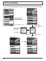
Picture Profiles
Up to 16 combinations of picture adjustment values (in the Picture menu and Advanced settings) can be stored in
the display memory as profiles and applied as needed, for a convenient way to enjoy your preferred picture settings.
Normalise
Picture Mode
Contrast
Dynamic
25
Brightness
0
Colour
6
Hue
0
Sharpness
5
White balance
Colour Management
Normal
Off
Advanced settings
Normalise
Save profiles(page 25)
Load profiles(page 26)
Edit profiles(page 27)
Memory save
Memory load
Memory edit
Onscreen display
On
All Aspect
Off
Studio mode
Off
Function button assign
Picture Mode
Normal
Contrast
25
Brightness
0
Colour
6
Hue
0
Sharpness
5
White balance
Normal
Colour Management
Off
Advanced settings
Scrolling bar
Lock profiles(page 28, 29)
Memory lock
Save profiles
Save the picture
adjustment values in the
MEMORY1 profile
Edit the profile
Delete or rename
the profile
My Memory
MEMORY2
MEMORY3
MEMORY4
MEMORY1
MEMORY2
MEMORY3
MEMORY4
Locked profile
MEMORY16
MEMORY16
Load the profile
Original picture
Custom picture
Normalise
Normalise
Picture Mode
Normal
Picture Mode
Normal
Contrast
0
Contrast
25
Brightness
0
Brightness
0
Colour
0
Colour
6
Hue
0
Hue
0
Sharpness
0
Sharpness
5
White balance
Colour Management
Advanced settings
24
Apply the MEMORY1
profile
Normal
Off
White balance
Colour Management
Advanced settings
Normal
Off
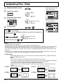
Picture Profiles
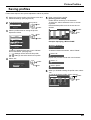
Saving profiles
Follow these steps to save picture adjustment values as profiles.
1
Specify the picture quality in the Picture menu and
Advanced settings. (see page 20-23)
2
In the Picture menu, select “Memory save”.
2 OK
Memory save
5
Memory load
Memory edit
3
1
select
Select a profile name for saving the picture
adjustment values.
2 OK
Enter a name for the profile.
[Entering profile names]
Profile names can be up to 16 characters.
To enter text, select characters in the on-screen
keyboard.
Edit the default profile name in the text box as
desired.
1 select
Memory name input
A
N
a
n
0
!
_
Memory save
1. [
2. [
]
MEMORY1
]
MEMORY2
3. [ 1]
4. [ ]
MEMORY3
1
select
]
MEMORY13
]
MEMORY14
15. [
16. [
]
MEMORY15
]
MEMORY16
E
R
e
r
4
%
<
F
S
f
s
5
&
>
MEMORY1█
G H I
T U V
g h i
t u v
6 7 8
’
+
(
)
[
J
W
j
w
9
–
]
K
X
k
x
L M
Y Z
l m
y z
Space
/ = ?
{
}
,
Cancel
All delete
Delete
@
.
\
;
2
OK
ˆ
:
Select “All delete”.
1
MEMORY1█
All text is deleted.
To delete individual characters, select “Delete”.
Select “M”.
2
M█
Repeat this process to enter the next character.
Select “Ok”.
1
select
2
OK
MY█
Save the adjusted value in MEMORY1
Cancel
Select “Y”.
3
Memory save
Ok
D
Q
d
q
3
$
~
Example: Specifying “MY PICTURE”
Profiles are labeled with these icons to indicate
their locked status. (see page 26)
[ ], [ ]:Settings can be saved in this profile.
[ ], [ ]:Settings cannot be saved in this profile.
4
C
P
c
p
2
#
|
Ok
MEMORY4
13. [
14. [
B
O
b
o
1
”
`
Select “Space”.
4
MY
6
█
When you finished entering the profile name, select
“Ok”.
To cancel saving the profile, select “Cancel”.
1 select
Memory name input
A
N
a
n
0
!
_
B
O
b
o
1
”
`
C
P
c
p
2
#
|
D
Q
d
q
3
$
~
E
R
e
r
4
%
<
Ok
F
S
f
s
5
&
>
MY PICTURE█
G H I
T U V
g h i
t u v
6 7 8
’
+
(
)
[
J
W
j
w
9
–
]
K
X
k
x
L M
Y Z
l m
y z
Space
/ = ?
{
}
,
Cancel
All delete
Delete
@
.
\
;
2
OK
ˆ
:
25
Picture Profiles
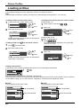
Loading profiles
Load profiles and apply the picture adjustment values to the display as follows.
Note:
Loaded profiles are stored in memory according to the selected input terminal (SLOT1, 2, 3 or PC IN).
<Loading profiles from the Picture menu>
<Loading profiles directly from the remote control>
1
To load profiles 1–9
In the Picture menu, select “Memory load”.
2 OK
Memory save
Memory load
Memory edit
2
1
select
Select the profile to load.
1. [ ]
2. [ 1]
12. [ 2]
MEMORY1
MEMORY2
MEMORY12
2
OK
1
select
Profiles are labeled with these icons to indicate their
locked status. (see below)
<Loading profiles from
1
2
Press
on the remote control>
1
2
Press a button in the range
.
Select “Ok”.
Memory load
Load from MEMORY2
Ok
1
select
2
OK
1
Cancel
To load profiles 10–16
Example: To load profile 16
1
to list the profiles.
Press
.
The profile number is displayed in the upper-right
corner of the screen.
16
Select the profile to load.
1. [ ]
2. [ 1]
12. [ 2]
–
MEMORY1
MEMORY2
MEMORY12
2
OK
1
select
2
Select “Ok”.
Memory load
1
select
2
OK
Load from MEMORY16
Profiles are labeled with these icons to indicate their
locked status. (see below)
Ok
Cancel
Loading locked profiles…
In the Picture menu, profiles are labeled with these icons to indicate their locked status.
:Lock1
:Lock2
Normalise
Picture Mode
Dynamic
Contrast
25
Brightness
0
Operations with locked profiles are restricted. (see page 28)
Picture adjustment values in the Picture menu cannot be changed, except for the “Picture Mode”. Once you edit the
“Picture Mode” setting, you can edit “Contrast”, “Brightness”, and other picture adjustment values.
Lock1
Picture adjustment values are shown.
Lock2
Picture adjustment values are hidden.
Normalise
Normalise
Picture Mode
Normal
Can be specified.
Picture Mode
Contrast
25
Brightness
0
Brightness
Colour
6
Colour
Hue
0
Sharpness
5
White balance
Colour Management
Advanced settings
26
Cannot be specified.
Normal
Off
Contrast
Hue
Sharpness
White balance
Colour Management
Advanced settings
Normal
Can be specified.
Cannot be specified.
Picture Profiles
Editing profiles
Delete or rename profiles as follows.
<Deleting profiles>
<Renaming profiles>
Note:
Locked profiles and profiles currently in use cannot be
deleted.
Note:
Locked profiles cannot be renamed.
1
In the Picture menu, select “Memory edit”.
2
Memory save
1
In the Picture menu, select “Memory edit”.
Memory save
OK
Memory edit
Memory load
Memory edit
2
Memory delete
2
OK
1
select
Select the profile to delete.
To delete all profiles, select “All delete”.
1. [
2. [
]
]
MEMORY1
MEMORY2
All delete
4
select
Select “Memory delete”.
Memory name change
3
1
2
OK
1
select
1
select
2
OK
2
OK
1
select
2
OK
1
select
2
OK
1
select
Select “Memory name change”.
Memory delete
Memory name change
3
4
Select the profile to rename.
1. [
2. [
]
]
MEMORY2
12. [
]
MEMORY12
MEMORY1
Enter a name for the profile.
Entering profile names
page 25
Select “Ok”.
Memory name input
Memory delete
A
N
a
n
0
!
_
Dlete the MEMORY1 data.
Ok
2
Memory load
Cancel
B
O
b
o
1
”
`
C
P
c
p
2
#
|
D
Q
d
q
3
$
~
E
R
e
r
4
%
<
Ok
5
F
S
f
s
5
&
>
MEMORY1█
G H I
T U V
g h i
t u v
6 7 8
’
+
(
)
[
J
W
j
w
9
–
]
K
X
k
x
L M
Y Z
l m
y z
Space
/ = ?
{
}
,
Cancel
All delete
Delete
@
.
\
;
ˆ
:
When you finished entering the profile name, select
“Ok”.
To cancel renaming the profile, select “Cancel”.
Ok
Cancel
1 select
2
OK
27
Picture Profiles
Locking profiles
You can lock saved profiles to restrict operations when the profiles are loaded. You can also set passwords.
<Locking and unlocking profiles>
1
2
Display the menu screen.
Select “Options” and hold
Picture
Setup
Pos. /Size
Sound
for 3 seconds or more.
2 OK
(3 seconds
or more)
1 select
4
Enter a 4-digit password.
The default password is
“0123”.
5
Select “OK”.
Input password
OK
Options
3
6
Select “Memory lock”.
Onscreen display
On
All Aspect
Off
Studio mode
Off
Function button assign
2
OK
1 select
Scrolling bar
Memory lock
CANCEL
1
select
2
OK
Select the profile and specify the desired lock
setting.
MEMORY1
Lock1
MEMORY2
Off
MEMORY12
Off
isf Mode
Off
2
1
set
select
Change password
7
Exit the menu.
or
Once a profile is locked, the following operations are restricted when the profile is loaded.
Setting
Editing the Profile
(Memory edit)
Off (unlocked) Allowed
Lock1
Prohibited
Lock2
Prohibited
Editing Picture Adjustment
Values via the Menu
(Picture menu, Advanced
settings)
Allowed
Prohibited (picture adjustment
values are shown)
Prohibited (picture adjustment
values are hidden)
Saving Picture Adjustment Values
(Memory save)
Allowed
Allowed
Prohibited
<Changing passwords>
1
Follow steps 1–5 in the previous procedure,
<Locking and unlocking profiles>.
2
Select “Change password”.
MEMORY1
Lock1
MEMORY2
Off
MEMORY12
Off
isf Mode
Off
2
OK
1
select
3
Enter a new 4-digit password.
4
Select “OK”.
Input new password
Change password
OK
5
Note:
Make a note of the new password to remember it.
28
Exit the menu.
CANCEL
1
select
2
OK
or
Picture Profiles
<isf Mode Setting>
Switches to “Picture Mode” mode display.
1
Follow steps 1–5 in the previous procedure,
<Locking and unlocking profiles>.
2
Select “isf Mode”.
MEMORY1
Lock1
MEMORY2
Off
MEMORY12
Off
isf Mode
Off
2
set
1
select
Change password
3
4
Specify “On” or “Off”.
Exit the menu.
or
Specifying “On” for isf Mode changes the “Picture Mode” mode display as follows.
“Picture Mode” mode display
Normalise
Picture Mode
Normal
Contrast
25
Brightness
0
Colour
6
Hue
0
Sharpness
5
Mode display when
isf Mode: Off
Normal
Dynamic
Cinema
Monitor
isf Mode: On
Normal
isf Mode Day
isf Mode Night
Monitor
isf Mode: Off
isf Mode: On
is selected
Picture Mode
Picture Mode
Normal
Normal
Dynamic
isf Mode Day
Cinema
isf Mode Night
Monitor
Monitor
29
Adjusting Pos. /Size
1
2
Display the menu screen.
During “Digital”, “SDI” and
“HDMI” input signal.
Select “Pos. /Size”.
Normalise
2
Picture
OK
Setup
H-Pos
0
Pos. /Size
H-Size
0
Sound
1
3
select
Select the item and set.
Normalise
Auto Setup
4
Auto Setup
H-Pos
0
H-Size
0
V-Pos
0
V-Size
0
1:1 Pixel Mode
Off
Display size
Off
2
adjust or select
1
select
V-Pos
0
V-Size
0
1:1 Pixel Mode
Off
Display size
Off
During “Component”, “RGB”
and “PC” input signal.
Normalise
Auto Setup
Exit the menu.
or
H-Pos
0
H-Size
0
V-Pos
0
V-Size
0
Dot Clock
Clock Phase
Using
for menu display
0
-16
1:1 Pixel Mode
Off
Display size
Off
To display a menu for adjustment of the Pos. /Size menu on the bottom of
the screen, press
H-Pos
0
To hide the menu, press
or
2
adjust or select
1
select the menu
.
Notes:
• Unadjustable items are grayed out.
Adjustable items differ depending on the input signal and the display mode.
• Adjustment details are memorized separately for different input signal formats (Adjustments for component signals
are memorized for 525 (480) / 60i • 60p, 625 (575) / 50i • 50p, 1125 (1080) / 60i • 50i • 60p • 50p • 24p • 25p •
30p • 24sF, 1250 (1080) / 50i, 750 (720) / 60p • 50p each, and RGB/PC/Digital signals are memorized for each
frequency.)
• If a “Cue” or “Rew” signal from a VCR or DVD player is received, the picture position will shift up or down. This
picture position movement cannot be controlled by the Picture Pos./Size function.
● Auto Setup
● H-Pos
Automatically adjust H-Pos / V-Pos / Clock Phase / Dot Clock and set H-Size / V-Size the standard
value when RGB signal is input.
Notes:
• If the dot clock frequency is 162 MHz or higher, Dot Clock cannot be made.
• If the image is that the edge is hardly figured out or shadowy, that cannot be adjusted automatically.
In such case, press Auto Setup again after changing the image to the clearer one.
• When DVI-D is input, Clock Phase cannot be adjusted automatically.
• Select Normalise in Pos. /Size and press the OK button when appropriate adjustment cannot be
made.
Adjust the horizontal position.
● V-Pos Adjust the vertical position.
● H-Size Adjust the horizontal size.
30
● V-Size Adjust the vertical size.
Adjusting Pos. /Size
● Dot Clock
(During “Component”, “RGB” and “PC” input signal)
Periodic striped pattern interference (noise) may occur when a striped pattern is displayed.
If this happens, adjust so that any such noise is minimized.
● Clock Phase
(During “Component”, “RGB” and “PC” input signal)
Eliminate the flickering and distortion.
● 1:1 Pixel Mode
Adjusts the display size when 1125i, 1125p or 1250i signal is input.
Notes:
• Select On when you would like to replay 1920 × 1080 input signal.
• Applicable input signal;
1125 (1080) / 50i • 60i • 24sF • 24p • 25p • 30p • 50p • 60p, 1250 (1080) / 50i
• Select Off when flickering is shown around the image.
• H-Size, V-Size and Dot Clock cannot be adjusted when On is selected.
Off
● 1:1 Pixel Mode
(2k1k)
On
When the input signal is a 2k1k signal (2048 × 1080 / 24p, 2048 × 1080 / 24sF), the display
size is adjusted as follows.
(For 2k1k signals)
Off
On (left)
On (Centre)
On (Right)
Note:
2k1k signals can only be received when the Dual Link HD-SDI Terminal Board (TY-FB11DHD)
is installed.
● Display size
Adjusts the image display size on screen.
Off: Sets the normal image display size on screen.
On: Sets the image display size approximately 95 % of the normal image display.
Notes:
Off
On
• “Display size” can be modified when “Studio mode” in the Options menu is “On”. When
“Studio mode” is “Off”, this setting is “Off” and cannot be changed. (see page 41)
• This setting is valid only when the input signals are as follows;
525i, 525p, 625i, 625p, 750/60p, 750/50p, 1125/60i, 1125/50i, 1125/24sF, 1125/25p,
1125/24p, 1125/30p, 1125/60p, 1125/50p, 1250/50i (Component Video, RGB, DVI, SDI,
HDMI)
• When “Display size” is set to “On”, “H-Pos” and “V-Pos” in “Pos. /Size” can be adjusted.
• Refer to each board’s operating instruction for DVI, SDI, HDMI’s corresponding signals.
Helpful Hint (
Normalise
Normalization)
While the Pos. /Size display is active, if the OK button is pressed during “Normalise”, then all adjustment values
are returned to the factory settings.
31
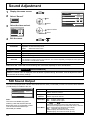
Sound Adjustment
1
2
Display the menu screen.
Normalise
Sound Mode
Select “Sound”
2
Picture
Setup
OK
Pos. /Size
Sound
3
1
select
2
adjust or select
1
select
Select the item and set.
Normal
Bass
0
Mid
0
Treble
0
Balance
0
Surround
Volume
Off
1
Normalise
Sound Mode
Normal
Bass
0
Mid
0
Treble
0
Balance
0
Off
Surround
1
Volume
4
Exit the menu.
or
Item
Sound Mode
Bass
Mid
Treble
Balance
Surround
Volume
Details
Normal: Emits the original sound.
Dynamic: Accentuates sharp sound.
Clear:
Attenuates human voice.
Adjusts low pitch sounds.
Adjusts normal sounds.
Adjusts high pitch sounds.
Adjusts left and right volumes.
Select On or Off.
The benefits of surround sound are enormous. You can be completely enveloped in sound; just as if
you were at a concert hall or cinema.
Adjusts the sound volume level.
Note: Bass, Mid, Treble and Surround settings are memorized separately for each Sound Mode.
Helpful Hint (
Normalise
Normalisation)
While the “Sound” menu is displayed, if the OK button is pressed during “Normalise”, then all adjustment values
are returned to the factory settings.
SDI Sound Output
This menu is displayed when HD-SDI Terminal Board with audio (TY-FB10HD) or Dual Link HD-SDI Terminal Board
(TY-FB11DHD) is installed to the unit.
SDI Sound Output
2/2
Left Channel
Channel 1
Right Channel
Channel 2
Sound Out
On
Level Meter
Off
Note:
This menu is available only when
selecting a slot that HD-SDI Terminal
Board with audio (TY-FB10HD) or Dual
Link HD-SDI Terminal Board (TYFB11DHD) is installed.
32
Item
Left Channel
Right
Channel
Sound Out
Level Meter
Details
Channel 1 to Channel 16
Selects left audio channel.
Channel 1 to Channel 16
Selects right audio channel.
On
Off
On: Enables audio output.
Off: Disables audio output.
Off
1-8ch
9-16ch
Sets audio channels to show in the audio level meter.
8 channels are displayed in the audio level meter; 4 channels
each on both right and left sides of the display.
Off: Hides the audio level meter.
1-8ch: Displays the audio level meter (1-8ch)
9-16ch: Displays the audio level meter (9-16ch)
Screensaver (For preventing image retention)
Do not display a still picture, especially in 4:3 mode, for any length of time.
If the display must remain on, a Screensaver should be used.
1
2
Display the menu screen.
Start
Select “Setup”.
2
OK
Function
Negative image
Side panel
High
Setup
Wobbling
Off
Pos. /Size
Peak limit
Off
Picture
Sound
3
Screensaver
1
select
2
OK
1
select
2
change
1
select
Select “Screensaver”.
Signal
Screensaver
Component/RGB-in select
RGB
Off
External scaler mode
4
Power save
Off
Standby save
On
Power management
Off
Function selection
Select “Function” and select the
desired function.
Screensaver
Start
Function
5
Negative image
Side panel
High
Wobbling
Off
Peak limit
Off
Negative image
White screen
Negative image
Scrolling bar only
Scrolling bar only
Overlay scrolling bar
: Negative image will be displayed on the screen.
: A white bar will scroll from left to right. The
image won’t be displayed.
Overlay scrolling bar : The brightness of the image will be decreased
and a white bar will scroll on it.
White screen
: The whole screen will be white.
Start setting
Select “Start”.
Screensaver
1
select
2
OK
Start
Function
Negative image
Side panel
High
Wobbling
Off
Peak limit
Off
The menu screen will disappear and the Screensaver will be activated.
To stop the Screensaver under On, press
or any buttons on
the main unit.
Note: When the display is turned off, the Screensaver will be
deactivated.
33
Screensaver (For preventing image retention)
Reduces screen image retention
These functions prevent the occurrence of an “image retention” on the display when turned ON.
Wobbling: Automatically shifts the display image (therefore unnoticeable to the eye) to prevent image retention
of sharper contour of image.
On1: Shifts the image every 30 seconds.
On2: Shifts the image at a dot level pitch depending on screen-detection.
Peak limit: Suppresses image contrast (peak brightness).
Note: When a still picture is viewed for an extended time, the screen may become slightly darker. (see
page 45)
1
2
Select “Wobbling” or “Peak limit”.
Select “On1”, “On2” or “Off”
(Wobbling).
Select “On” or “Off” (Peak
limit).
Screensaver
Start
Function
Negative image
Side panel
High
Wobbling
Off
Peak limit
Off
2
change
1
select
Side Panel Adjustment
Do not display a picture in 4:3 mode for an extended
period, as this can cause an image retention to remain on
the side panels either side of the display field.
To reduce the risk of such an image retention, illuminate
the side panels.
This function may be applicable to the non-picture area.
1
2
4:3
Screen Display
Image
retention
Select “Side panel”.
Adjust the menu.
Screensaver
Start
Function
3
Side panel
Negative image
Side panel
High
Wobbling
Off
Peak limit
Off
Exit from Screensaver.
Off
2
change
1
select
Low
Mid
High
or
Notes:
• To reduce the occurrence of image retention, set the “Side panel” to “High”.
• The side panels may flash (alternate black / white) depending on the picture being shown on the screen. Using
Cinema mode will reduce such flashing.
34
Specifying the scaler
This menu can be used to specify whether the built-in scaler or an external scaler is used for scaler functions such
as resizing and picture quality adjustment.
The setting is valid with the following input signals.
1125 (1080) / 24p•25p•30p•50p•60p
1
2
Display the menu screen.
Signal
Screensaver
Select “Setup”.
Component/RGB-in select
2
Picture
OK
RGB
External scaler mode
Setup
Pos. /Size
1
Sound
3
select
Select “External scaler mode” and set.
Signal
Screensaver
Component/RGB-in select
RGB
External scaler mode
Off
Power save
Off
Standby save
On
Power management
Off
Auto power off
Off
OSD design
OSD position
OSD Language
Type1
Upper left
English (UK)
2
change
1
select
Off
Power save
Off
Standby save
On
Power management
Off
Auto power off
Off
OSD design
Type1
OSD position
Upper left
OSD Language
English (UK)
Off
On
Off: Use the built-in scaler.
On: Use an external scaler.
Note:
Selecting “On” in this setting deactivates the following settings and
disables these operations.
Pos. /Size menu: H-Size, V-Size, 1:1 Pixel Mode, Display size
(see page 30, 31)
Picture menu:
Brightness, Colour, Hue, Sharpness, Memory save,
Memory load (see page 21, 25, 26)
Advanced settings: Cinema reality, Noise reduction (see page 23)
Signal menu:
XGA Mode (see page 39)
Options menu:
All Aspect (see page 41)
ASPECT Controls (see page 17)
“EXT. SCALER” is displayed in the menu screen to indicate that an
external scaler is in use.
EXT.SCALER
Normalise
Picture Mode
Normal
Contrast
25
Brightness
Colour
Hue
4
Exit the menu.
or
35
Reduces power consumption
1
2
Display the menu screen.
Signal
Screensaver
Select “Setup”.
Component/RGB-in select
2
Picture
OK
Setup
Pos. /Size
1
Sound
3
Component/RGB-in select
RGB
Off
Standby save
On
Power management
Off
Auto power off
Off
OSD design
Type1
OSD position
Upper left
Power save
Off
Standby save
On
Power management
Off
Auto power off
Off
OSD design
Type1
OSD position
Upper left
1
select
English (UK)
Exit the menu.
● Power save
● Standby save
● Power management
● Auto power off
change
English (UK)
Off
External scaler mode
OSD Language
2
Off
Power save
OSD Language
Screensaver
36
select
Select the item and set.
Signal
4
RGB
External scaler mode
or
When this function is turned On, luminous level of the Plasma Display is
suppressed, so power consumption is reduced.
When this function is turned On, power consumption of the microcomputer is
reduced during power supply standby (see page 12, 14, 15), so standby power of
the set is reduced.
When this function is set to On, it operates under the following conditions to turn
the power on or off automatically.
When no pictures (HD/VD sync signals) are detected for 30 or so seconds during
PC IN signal input:
→ Power is turned off (standby); the power indicator lights up orange.
When pictures (HD/VD sync signals) are subsequently detected:
→ Power is turned on; the power indicator lights up green.
Notes:
• This function operates only during PC IN signal input.
• This function is effective when “Sync” is set to “Auto” and “Component / RGB-in
select” is set to “RGB”.
Equipment power supply is turned Off when there is no signal.
When this is set to On, the power supply of the unit goes Off 10 minutes after the
input signals stop.
Note:
This function is effective for input signals except PC IN terminal.
Customizing the On-Screen Menu Display
Specify the background colour and display position of on-screen menus as follows.
1
2
Display the menu screen.
Signal
Screensaver
Select “Setup”.
2
Picture
Component/RGB-in select
OK
RGB
External scaler mode
Setup
Pos. /Size
1
Sound
3
Specify the background colour.
Select “OSD design” and choose the background colour (transparency).
Standby save
Off
Standby save
On
Power management
Off
Auto power off
Off
OSD design
Type1
OSD position
Upper left
OSD Language
English (UK)
On
Power management
Off
Auto power off
Off
OSD design
Type1
OSD position
Upper left
OSD Language
4
select
Off
Power save
English (UK)
2
change
1
select
Type2
Type1
Type3
Specify the display position.
Select “OSD position” and choose the display position.
Standby save
On
Power management
Off
Auto power off
Off
OSD design
Type1
OSD position
Upper left
OSD Language
Each time you press
Display example
2
change
1
select
English (UK)
or
, the on-screen menu display position changes.
Upper left
Centre
5
Exit the menu.
or
37
Setup for Input Signals
Component / RGB-in select
Select to match the signals from the source connected to the Component / RGB input terminals.
Y, PB, PR signals
“Component”
RGB signals
“RGB”
1
2
Display the menu screen.
Select “Setup”.
Picture
2
OK
1
select
Setup
Pos. /Size
Sound
3
Select “Component / RGB-in select” and set.
Signal
Screensaver
2
change
1
select
Component/RGB-in select
RGB
4
External scaler mode
Off
Power save
Off
RGB
Component
Exit the menu.
or
Notes:
• Selection may not be possible, depending on which optional board is installed.
• Make setting of the selected input terminal (SLOT1, SLOT2, SLOT3 or PC IN).
YUV / RGB-in select
Select to match the signals from the source connected to the DVI input terminals.
YUV signals
“YUV”
RGB signals
“RGB”
1
2
Display the menu screen.
Select “Setup”.
Picture
2
OK
1
select
2
change
1
select
Setup
Pos. /Size
Sound
3
Select “YUV / RGB-in select” and set.
Signal
Screensaver
YUV/RGB-in select
RGB
4
External scaler mode
Off
Power save
Off
Exit the menu.
YUV
RGB
or
Notes:
• Selection may not be possible, depending on which optional board is installed.
• Make setting of the selected input terminal (SLOT1 or SLOT2).
38
Setup for Input Signals
Signal menu
Note:
“Signal” setup menu displays a different setting condition for each input signal.
For RGB
Signal
Screensaver
Component/RGB-in select
RGB
External scaler mode
Off
[ RGB ]
Signal
Sync
Auto
XGA Mode
1024 ×768
H-Freq.
33.7 kHz
60.0 Hz
Power save
Off
Standby save
On
V-Freq.
Power management
Off
Signal Format
Auto power off
Off
OSD design
Type1
OSD position
Upper left
OSD Language
1125(1080)/60i
For Component
For Digital
English (UK)
[ Component ]
Signal
XGA Mode
1024 ×768
H-Freq.
33.7 kHz
V-Freq.
60.0 Hz
Signal Format
[ Digital ]
Signal
H-Freq.
33.7 kHz
V-Freq.
60.0 Hz
Dot Clock Freq.
1125(1080)/60i
Signal Format
108.0 MHz
1125(1080)/60i
XGA Mode
This menu is displayed when the input signal is analog (Component/PC). This unit supports three types of XGA
signals with 60Hz vertical frequency having different aspect ratios and sampling rates (1,024 × 768 @ 60Hz, 1,280
× 768 @ 60Hz, and 1,366 × 768 @ 60Hz). Be sure to make settings in accordance with the input signal in order to
achieve a more appropriate and attractive display.
In addition, after making this setting, be sure to make each adjustment (such as “Auto Setup”) on the “Pos. /Size”
menu as necessary. (see page 30)
Signal
XGA Mode
[ Component ]
1024 ×768
2
change
1
select
1024×768
1280×768
1366×768
39
Setup for Input Signals
Sync
Select Signal from the “Setup” menu during RGB input signal.
Signal
Sync
XGA Mode
[ RGB ]
Auto
1024 ×768
2
change
1
select
Auto
on G
VBS
Setting RGB sync signal:
Confirm that the input is set to RGB input (this setting is valid only for RGB input signal).
Auto: The H and V sync or synchronized signal are automatically selected. If both input, it is selected the H and
V sync.
on G: Uses a synchronized signal on the Video G signal, which is input from the G connector.
VBS: Uses a synchronized signal of Composite Sync input, which is input from the HD connector.
SDI Through
Set the active through function of the Dual Link HD-SDI Terminal Board (TY-FB11DHD).
Note:
Settings can only be performed for this menu when a slot mounted with a Dual Link HD-SDI Terminal Board
(TY-FB11DHD) is selected.
Signal
SDI Through
[ Digital ]
Off
Off
On:
Off:
2
change
1
select
On
Enables active through.
Disables active through.
Input signal display
Displays the frequency and the type of the current input signal.
This display is valid only for Component / RGB / PC and Digital input signal.
Display range:
Horizontal 15 - 110 kHz
Vertical 48 - 120 Hz
The dot clock frequency is displayed during digital signal input.
40
H-Freq.
33.7 kHz
V-Freq.
60.0 Hz
Signal Format
1125(1080)/60i
H-Freq.
33.7 kHz
V-Freq.
60.0 Hz
Dot Clock Freq.
Signal Format
108.0 MHz
1125(1080)/60i
Options Adjustments
1
2
3
Display the menu screen.
Select “Options”.
Press
Onscreen display
On
All Aspect
Off
Studio mode
Function button assign
for more than 3 seconds.
Picture
Memory lock
2
OK (more than
3 seconds)
1
select
2
set
1
select
Setup
Pos. /Size
Sound
Off
Scrolling bar
Options
4
Select the item and set.
Onscreen display
On
All Aspect
Off
Studio mode
Off
Function button assign
Scrolling bar
Memory lock
5
Exit the menu.
or
Adjustments
Item
Onscreen display
On: Displays all the following on screen.
• Power on display
• Input signal switch display
• No signal display
• Mute after
was pressed.
Off: Hides all the items above from view.
Sets All Aspect mode (advanced aspect setting) or default aspect mode.
With each press of
All Aspect
button, the aspect changes in the selected mode.
Off: Default aspect mode
On: All Aspect mode
Aspect mode of each setting is as follows:
(Example: HD signal)
Off
4:3→4:3 Full→Zoom1→Zoom2→Zoom3→16:9→14:9→Just
On
4:3 (1)→4:3 (2)→4:3 Full→Zoom1→Zoom2→Zoom3→16:9→14:9→Just1→Just2
For switching functions in setting menus used for television studio applications.
Studio mode: On
White balance
Studio mode
Studio Gain
Display size
“Studio” not available.
Cannot be specified
Can be switched On and Off. (set to “Off” and cannot be changed).
Cannot be specified
Can be switched On and Off. (set to “Off” and cannot be changed).
Specifies the function activated when the
Function button
assign
button on the remote control is pressed.
Scrolling bar: Activates the Scrolling bar only screensaver. After 15 minutes, the display enters standby
mode.
Test patterns: Each time you press
Memory lock
Studio mode: Off
“Studio” can be selected.
, a different test pattern is displayed (seven in all).
Locks or unlocks saved profiles. Also for setting passwords. (see page 28)
41
Watching Videos and DVDs
If you have applicable equipment connected to the Display, you can easily watch videos and DVDs using the
Display’s remote control.
You can select the external equipment to access.
To operate other manufacturers’ equipment, you need to register the code for the equipment. (see page 43)
1
Select the input mode. (see page 13)
INPUT
HDMI1
DISPLAY
HDMI2
HDMI3
INPUT
HDMI4
COMPONENT
PC
PC
COMPO.
HDMI
フ
2
Select the remote control mode.
3
Operate the connected equipment, pointing Display’s remote
control at the equipment.
DISPLAY VCR DBS/CBL DVD
CH INPUT
Press the key to select.
Example
VCR MODE
VCR Record
–
Skip Reverse/Forward
Rewind/Fast Forward
Reverse/Forward
Stop
Stop
Pause
Pause
Play
Play
(For other operations, see page 47)
42
DVD MODE
Record
DISPLAY
Watching Videos and DVDs
Programming the Remote to Operate Peripheral Equipment
You can operate other manufacturers’ equipment using this Display’s remote control.
1
2
3
4
Connect the external equipment to the Display and Power Off the
external equipment.
Press both buttons simultaneously for more
+
than 3 seconds.
DISPLAY
Release the buttons when the equipment selection
buttons start flashing.
Select the equipment.
VCR DBS/CBL DVD
PC
COMPO.
The selected button remains lit (other buttons are not lit).
HDMI
フ
Input the equipment’s 4-digit remote control
code.
CH INPUT
(see page 47, 48)
5
Operate the equipment with the remote
control.
(see page 47)
The external equipment turns On.
Press to return to the Display mode.
DISPLAY
DISPLAY
If the equipment does not operate with the remote control
• When your equipment has a single code
Input the remote control code again
• When your equipment has multiple codes
Change the code with 4 above and test again
Note:
Registration will fail if the wrong code is input or it takes more than 30 seconds to register.
To find a code not listed in the code list
This procedure searches all codes and is called the “sequence method.”
1 After step 3 above, change the code and test.
2 When the correct code is found.
store
change
Operate the equipment with the remote control.
(see page 47)
• Repeat until the code is found.
• It may take many attempts before the correct code is
found.
43
Shipping condition
This function allows you to reset the unit to the factory setting.
1
2
Display the menu screen.
Select “Setup”.
Picture
2
OK
1
select
1
select
1
select
2
OK
1
select
2
OK
Setup
Pos. /Size
Sound
3
Select “OSD Language”.
Signal
Screensaver
Component/RGB-in select
RGB
External scaler mode
Off
Power save
Off
Standby save
On
Power management
Off
Auto power off
Off
OSD design
Type1
OSD position
Upper left
OSD Language
English (UK)
4
Press
5
Select “YES”.
for more than 5 seconds.
Reset to factory default.
YES
6
NO
Select “YES” and wait for 10 sec.
All saved data will be erased
CONTINUE?
YES
NO
Note:
Press
to return to Setup menu when confirmation screen is displayed.
[from the unit]
1 Press the MENU button till the Setup menu is displayed.
2 Press the
or
button to select “OSD Language”.
3 Press the ENTER button for more than 5 seconds.
4 Press the
or
button to select “YES”.
5 Press the ENTER button.
6 Press the
or
button to select “YES”.
7 Press the ENTER button and wait for 10 sec.
Executing this function restores all settings and adjustment values in the following menus to the
factory-set default values, as shipped.
On-screen menu: Picture, Advanced settings, Setup, Pos. /Size, Sound, Options
Unlocking profiles (Memory lock: Off, Password: 0123)
44
Troubleshooting
Before you call for service, determine the symptoms and make a few simple checks as shown below.
Symptoms
Picture
Checks
Sound
Electrical Appliances
Cars / Motorcycles
Fluorescent light
Volume
(Check whether the mute function has been activated on the remote control.)
Interference
Noisy Sound
Normal Picture
No Sound
No Picture
No Sound
No Picture
Normal Sound
Not plugged into AC outlet
Not switched on
Picture and Brightness/Volume setting
(Check by pressing the power switch or stand-by button on the remote control.)
If a signal with a non-applicable colour system format, or frequency is input, only
the input terminal indication is displayed.
No Colour
Normal Sound
Colour controls set at minimum level
(see page 20-23)
No remote control operations can be performed.
A cracking sound is sometimes heard from the unit.
The top or bottom of the picture on the screen is cut off
when I use the zoom function.
Areas at the top and bottom of the screen where the
image is missing appear when I use the zoom function.
I can hear sounds coming from inside the unit.
Check whether the batteries have discharged completely and, if they have not,
whether they were inserted properly.
Check whether the remote control sensor is exposed to an outdoor light or a strong
fluorescent light.
Check whether the remote control designed specifically for use with the unit is
being used. (The unit cannot be operated by any other remote control.)
If there is nothing wrong with the picture or sound, this is the sound of the cabinet
undergoing very slight contractions in response to changes in the room temperature.
There are no adverse effects on the performance or other aspects.
Adjust the position of the picture on the screen.
When using a video software program (such as a cinema size program) with a
screen wider than one in the 16:9 mode, blank areas separate from the images are
formed at the top and bottom of the screen.
When the power is turned on, a sound of the display panel being driven may be
heard: This is normal and not indicative of malfunctioning.
This Plasma Display uses special image processing. Hence a slight time lag may occur between image and audio, depending on the type of
input signal. However, this is not a malfunction.
Plasma Display panel
Symptoms
The screen darkens slightly
when bright pictures with
minimal movements are shown.
It takes a while for the picture to
appear.
The edges of the images flicker.
The brightness on both sides of
images in the 4:3 mode changes.
Some parts of the screen do not
light up.
Image retention appears
Whirring sounds can be heard
from the display unit.
Check
The screen will darken slightly when photos, still images of a computer or other pictures with minimal
movements are shown for an extended period. This is done to reduce image retention on the screen and
the shortening of the screen’s service life: It is normal and not indicative of malfunctioning.
The unit digitally processes the various signals in order to reproduce esthetically pleasing images. As
such, it sometimes takes a few moments for the picture to appear when the power has been turned on,
when the input has been switched.
Due to the characteristics of the system used to drive the panel, the edges may appear to flicker in the
fast-moving parts of the images: This is normal and not indicative of malfunctioning.
When viewing the side panels at the “High” or “Mid” setting, the brightness on both sides may change
depending on the kind of program shown: This is normal and not indicative of malfunctioning.
The plasma display panel is manufactured using an extremely high level of precision technology,
however, sometimes some parts of the screen may be missing picture elements or have luminous spots.
This is not a malfunction.
Do not allow a still picture to be displayed for an extended period, as this can cause a permanent image
retention to remain on the Plasma Display.
Examples of still pictures include logos, video games, computer images, teletext and images displayed in
4:3 mode.
Note:
The permanent image retention on the Plasma Display resulting from fixed image use is not an operating
defect and as such is not covered by the Warranty.
This product is not designed to display fixed images for extended periods of time.
The display unit is fitted with a cooling fan to dissipate heat generated during normal use. The whirring
sound is caused by rotation of the fan and is not a malfunction.
45
List of Aspect Modes
Aspect mode
All Aspect: Factory setting
On
All Aspect: Off
16:9
14:9
16:9
14:9
Just
Just
Just1
Just2
–
4:3
4:3
4:3 (1)
4:3 (2)
–
4:3 Full
4:3 Full
Zoom
Zoom1
Zoom1
Zoom2
Zoom2
Zoom3
Zoom3
46
Picture
Enlarged screen
Description
The display of the pictures fills the screen.
In the case of SD signals, pictures with a 4:3 aspect
ratio are enlarged horizontally, and displayed. This
mode is suited to displaying anamorphic pictures with
a 16:9 aspect ratio.
Letterbox pictures with a 14:9 aspect ratio are
enlarged vertically and horizontally so that their
display fills the screen vertically and is slightly smaller
than the screen horizontally. The top and bottom
edges of the pictures are cut off. Side panels are
displayed at the left and right edges of the screen.
Pictures with a 4:3 aspect ratio are enlarged
horizontally so that the picture distortion is minimized.
The display of the areas around the left and right
edges of the screen is slightly elongated.
The pictures with a 4:3 aspect ratio among the 16:9
aspect ratio signals are enlarged horizontally so that
the picture distortion is minimized. The left and right
edges of the pictures are cut off. The display of the
areas around the left and right edges of the screen is
slightly elongated.
Pictures with a 4:3 aspect ratio are displayed with
their original aspect ratio. Side panels are displayed
at the left and right edges of the screen.
The pictures with a 4:3 aspect ratio among the 16:9
aspect ratio signals are displayed with their original
aspect ratio. The left and right edges of the pictures
are masked with side panels.
The pictures with a 4:3 aspect ratio among the 16:9
aspect ratio signals are enlarged horizontally so that
their display fills the screen. The left and right edges
of the pictures are cut off.
Letterbox pictures with a 16:9 aspect ratio are
enlarged vertically and horizontally so that their
display fills the screen. The top and bottom edges of
the pictures are cut off.
The letterbox pictures with a 2.35:1 aspect ratio
among the 16:9 aspect ratio signals are enlarged
vertically and horizontally so that their display fills the
screen. The top and bottom edges as well as the left
and right edges of the pictures are cut off.
Letterbox pictures with a 2.35:1 aspect ratio are
enlarged vertically and horizontally so that their
display fills the screen vertically and is slightly larger
than the screen horizontally. The top and bottom
edges as well as the left and right edges of the
pictures are cut off.
Remote Control Operation / Code List
The following explains how to operate external devices with the Display’s remote control.
Register the remote control codes (page 43) if you want to operate an external device from another manufacturer.
(see page 47, 48)
Note:
Operation may not be possible depending on the available memory size of the remote control.
This remote control is not designed to cover operation of all functions of all models.
Remote Control Operation List
This chart defines which keys are operational after programming (if needed) while in the selected remote control
mode, CABLE, DBS, VCR, or DVD.
KEY NAME
CH INPUT
–
DBS/CBL MODE
VCR MODE
(DBS)
DVD MODE
(CBL)
Power
Power
Power
Power
-
Menu
Menu
Functions
-
PPV/VOD
PPV/VOD
Return
-
Up/Down/Left/Right
Up/Down/Left/Right
Up/Down/Left/Right
-
Select
Select
Enter
Channel Up/Down
Channel Up/Down
Channel Up/Down
Channel Up/Down
0-9
-
0-9
Page Down/Up
0-9
Page Down/Up
0-9
Skip Reverse/Forward
TV/VCR Switch
TV/DBS Switch
TV/CBL Switch
-
Rewind/Fast Forward
Rewind/Fast Forward
Rewind/Fast Forward
Reverse/Forward
Record
Record *1
Record *1
Record
Stop
Stop
Stop
Stop
Pause
Pause
Pause
Still/Pause
Play
Play
Play
Play
*1: Combination type
Remote Control Code List
DBS / CABLE (Cable Set Top Box)
Brand
Code
Brand
Code
Brand
Code
Brand
Code
ABC
0003, 0008, 0014, 0017
GoldStar
0144
Paragon
0000
Starcom
0003
Americast
0899
Hamlin
0009, 0273
Philips
0317, 1305
Supercable
0276
Amino
1602, 1822
i3 Micro
1602
Pioneer
0144, 0533, 0877, 1877
Supermax
0883
Bell & Howell
0014
Jerrold
Pulsar
0000
Thomson
1256
Bell South
0899
0003, 0012, 0014, 0276, 0476,
0810
Quasar
0000
Tocom
0012
Clearmaster
0883
Memorex
0000
RadioShack
0883
Torx
0003
ClearMax
0883
Motorola
RCA
1256
Toshiba
0000
Coolmax
0883
0276, 0476, 0810, 1106, 1187,
1254, 1376
Regal
0273, 0279
Tristar
0883
Digeo
1187
Multitech
0883
Runco
0000
V2
0883
Digi
0637
Myrio
1602, 1822
Samsung
0144
Viewmaster
0883
Director
0476
Pace
0008, 0237, 1877
Scientific Atlanta
0008, 0017, 0477, 0877, 1877
Vision
0883
Dumont
0637
Panasonic
0000, 0107, 1786
Sejin
1602
Vortex View
0883
General Instrument
0003, 0276, 0476, 0810
Panther
0637
Sony
1006
Zenith
0000, 0525, 0899
DBS / CABLE ( Satellite Set Top Box)
Brand
Code
Brand
Code
Brand
Code
Brand
Code
AlphaStar
0772
GE
0566
Memorex
0724
Sony
0639, 1639, 1640
0869
Century
0856
General Instrument
0869
Mitsubishi
0749
Star Choice
Chaparral
0216
GOI
0775, 1775
Motorola
0869
Tivo
1142, 1442, 1443, 1444, 1538, 1539
Crossdigital
1109
Gradiente
0856
Next Level
0869
DirecTV
0099, 0247, 0392, 0566, 0639,
0724, 0749, 0819, 1076, 1108,
1109, 1142, 1377, 1392, 1414,
1442, 1443, 1444, 1538, 1539,
1609, 1639, 1640, 1749, 1856
Hisense
1535
Panasonic
0247, 0701
Toshiba
0749, 0790, 1285, 1749
Hitachi
0819, 1250
Paysat
0724
UltimateTV
1392, 1640
HTS
0775, 1775
Philips
Uniden
0724, 0722
Hughes Network
Systems
0749, 1142, 1442, 1443, 1444,
1538, 1539, 1749
0099, 0722, 0724, 0749, 0856,
1076, 1142, 1442, 1749
US Digital
1535
Proscan
0392, 0566
USDTV
1535
Humax
1790
Proton
1535
Voom
0869
Zenith
0856, 1856
Dish Network System
0775, 1005, 1170, 1171, 1505, 1775
Dishpro
0775, 1005, 1505, 1775
iLo
1535
RadioShack
0869
Echostar
0775, 1005, 1170, 1171, 1505, 1775
JVC
0775, 1170, 1775
RCA
0566, 0855, 0143, 1392
LG
1226, 1414
Samsung
1108, 1109, 1276, 1377, 1442, 1609
Expressvu
0775, 1775
Magnavox
0724, 0722
47
Remote Control Operation / Code List
Remote Control Code List (Continued)
VCR
Brand
Code
Brand
Code
Brand
Code
Brand
Code
ABS
1972
Gradiente
0000
Nikko
0037
Singer
0072
Admiral
0048, 0209
Harley Davidson
0000
Niveus Media
1972
Sonic Blue
0614, 0616, 1615, 1616
Adventura
0000
Harman/Kardon
0038, 0081
Noblex
0240
Sony
Aiko
0278
Harwood
0072
Northgate
1972
0000, 0032, 0033, 0035, 0636,
1032, 1232, 1972
Aiwa
0000, 0037, 0124
Hewlett Packard
1972
Olympus
0035
Stack 9
1972
Akai
0041
HI-Q
0047
Optimus
STS
0042
Alienware
1972
Hitachi
0000, 0041, 0042, 0089
0037, 0048, 0104, 0162, 0432,
0593, 1062, 1162, 1262
Sylvania
America Action
0278
Howard Computers
1972
Orion
0002, 0184, 0209, 0479, 1479
0000, 0035, 0043, 0081, 0593,
1593, 1781
American High
0035
HP
1972
Panasonic
Symphonic
0000, 0593, 1593
Asha
0240
1972
0037, 0278
0042, 0739, 0740, 0745, 1239,
1240
Systemax
Audiovox
Hughes Network
Systems
0035, 0162, 0225, 0614, 0616,
1035, 1062, 1162, 1262
Penney
0035, 0037, 0038, 0042, 0240,
1035, 1237
Tagar Systems
1972
Tatung
0041
0042
Teac
0000, 0041
Beaumark
0240
Humax
0739
Bell & Howell
0104
Hush
1972
Pentax
Broksonic
0002, 0121, 0184, 0209, 0479,
1479
iBUYPOWER
1972
Philco
0035
Technics
0035, 0162
Jensen
0041
Philips
0035, 0081, 0618, 0739, 1081, 1181
Teknika
0000, 0035, 0037
Calix
0037
JVC
0041, 0067
Thomas
0000
Canon
0035
KEC
0037, 0278
Pilot
0037
Tivo
Carver
0081
Kenwood
0038, 0041, 0067
Pioneer
0067
0618, 0636, 0739, 0740, 0745,
1239, 1240, 1503, 1996
CCE
0072, 0278
KLH
0072
Polk Audio
0081
TMK
0240
Citizen
0037, 0278, 1278
Kodak
0035, 0037
Presidian
1593
Toshiba
Colt
0072
LG
1037
Profitronic
0240
0043, 0045, 0845, 1008, 1145,
1503, 1972, 1996
Craig
0037, 0047, 0072, 0240
Linksys
1972
Proscan
0060, 1060
Totevision
0037, 0240
Curtis Mathes
0035, 0041, 0060, 0162, 1035
Lloyd’s
0000
Protec
0072
Touch
1972
Cybernex
0240
Logik
0072
Pulsar
0039
Unitech
0240
CyberPower
1972
LXI
0037
Quasar
0035, 0162, 1035, 1162
Vector
0045
Daewoo
0045, 0278, 1278
Magnasonic
0593, 1278
RadioShack
0000, 1037
Vector Research
0038
Dell
1972
Magnavox
0037
Video Concepts
0045
0042
0000, 0035, 0039, 0081, 0149,
0563, 0593, 1593, 1781
Radix
Denon
Randex
0037
Videomagic
0037
RCA
0042, 0060, 0149, 0240, 0807,
0880, 1035, 1060
Videosonic
0240
Viewsonic
1972
0000, 0035, 0037, 0047, 0048,
0104
Villain
0000
Voodoo
1972
Wards
0000, 0035, 0042, 0047, 0048,
0060, 0072, 0081, 0149, 0240
DirecTV
0739, 0740, 0745, 1239, 1240
Magnin
0240
Durabrand
0038, 0039
Marantz
0035, 0081
Dynatech
0000
Marta
0037
Electrohome
0037
Media Center PC
1972
Electrophonic
0037
MEI
0035
ReplayTV
0614, 0616, 1615, 1616
Emerex
0032
Memorex
Ricavision
1972
Emerson
0000, 0002, 0037, 0043, 0121,
0184, 0209, 0278, 0479, 0593,
1278, 1479, 1593
0000, 0035, 0037, 0039, 0047,
0048, 0104, 0162, 0209, 0240,
0479, 1037, 1162, 1237, 1262
Runco
0039
White Westinghouse
0072, 0209
Samsung
0045, 0240, 0739, 1014
XR-1000
0000, 0035, 0072
Realistic
MGA
0240, 0043
Sanky
0039, 0048
Yamaha
0038
Sansui
0000, 0041, 0067, 0209, 0479,
1479
Zenith
0000, 0033, 0039, 0209, 0479,
1479
ZT Group
1972
Fisher
0047, 0104
MGN Technology
0240
Fuji
0033, 0035
Microsoft
1972
Funai
0000, 0593, 1593
Mind
1972
Sanyo
0047, 0104, 0240
Garrard
0000
Minolta
0042
Scott
0043, 0045, 0121, 0184
Gateway
1972
Mitsubishi
0043, 0067, 0807
Sears
GE
0035, 0060, 0240, 0807, 1035,
1060
Motorola
0035, 0048
0000, 0035, 0037, 0042, 0047,
0104, 1237
MTC
0000, 0240
Sharp
0048, 0807, 0848
Go Video
0432, 0614
Multitech
0000, 0072
Shintom
0072
GoldStar
0037, 0038, 1237
NEC
0038, 0041, 0067, 0104
Shogun
0240
DVD Recorder / Player
Brand
Code
Brand
Code
Brand
Code
Brand
Code
Accurian
1072, 1416
Fisher
0670
Marantz
0539
Sanyo
0670, 0695, 0873
Advent
1016
Funai
0675, 1268, 1334
Memorex
0695, 0831, 1270
Sensory Science
1158
Aiwa
0641
Gateway
1073, 1077, 1158, 1194
Microsoft
0522, 1708
Sharp
0630, 0675, 0752, 1256
Akai
0695, 0770, 0899, 1089
GE
0522, 0815, 0717
Mintek
0717, 0839
Sharper Image
1117
Alco
0790
Go Video
0521, 1521
Sherwood
0633, 0770, 1043, 1077
0869
0715, 0741, 0744, 0783, 0833,
0869, 1044, 1075, 1099, 1158,
1304, 1730
Mitsubishi
Allegro
Momitsu
1082
Shinsonic
0533, 0839
NAD
0741
Sonic Blue
0869, 1099
Sony
0533, 0864, 1033, 1070, 1431,
1533
Amphion Media Works 0872
Apex Digital
0672, 0717, 0755, 0794, 0796,
0797, 0830, 1004, 1020, 1056,
1061, 1100
Go Vision
1071, 1072
NEC
0785
GoldStar
0741
Nesa
0717
Greenhill
0717
Next Base
0826
Sova
1122
Arrgo
1023
Harman/Kardon
0582, 0702
NexxTech
1402
Superscan
0821
Aspire Digital
1168, 1407
Hitachi
0573, 0664, 1247
Norcent
0872, 1003, 1107, 1265
SVA
0860, 1105
Audiovox
0790, 1071, 1072, 1121, 1122
Hiteker
0672
Onkyo
0503, 0627, 0792
Sylvania
0675, 0821, 1268
Axion
1071, 1072
Humax
1588
OptoMedia Electronics 0896
Symphonic
0675, 0821
Blaupunkt
0717
iLo
1348
Oritron
0651
Teac
0790
Blue Parade
0571
Initial
0717
Panasonic
Technics
0490, 0703
Broksonic
0695, 0868
Insignia
1268
0490, 0703, 1362, 1462, 1490,
1762, 1779, 2060, 2061, 2062
Technosonic
0730
Cinea
0831
Integra
0627
Philips
Theta Digital
0571
CineVision
0833, 0869, 0876
JBL
0702
0503, 0539, 0646, 0675, 0854,
1260, 1267, 1354
Toshiba
0503, 0695, 1045, 1154, 1588, 1769
Citizen
0695, 1277
Jensen
1016
Pioneer
0525, 0571, 0631
Coby
0778, 0852, 1086, 1107, 1165, 1177
JSI
1423
Polaroid
1020, 1061, 1086
Tredex
0800
JVC
0558, 0623, 0867, 1164
Polk Audio
0539
Urban Concepts
0503
Craig
0831
jWin
1049
Portland
0770
US Logic
0839
Curtis Mathes
1087
Kawasaki
0790
Presidian
0675, 1072
Venturer
0790
CyberHome
0816, 0874, 1023, 1024, 1117,
1129, 1502
Kenwood
0490, 0534
Prima
1016
Vizio
1064, 1226
KLH
0717, 0790, 1020, 1149
Proscan
0522
Xbox
0522, 1708
Daewoo
0705, 0784, 0833, 0869, 1169,
1172, 1234, 1242, 1441
Konka
0711, 0719, 0720
ProVision
0778
Yamaha
0490, 0539, 0545
Koss
0651, 0896, 1423
Qwestar
0651
Zenith
0503, 0591, 0741, 0869
Denon
0490, 0634
Landel
0826
RCA
Zoece
1265
Desay
1407
Lasonic
0798, 1173
0522, 0571, 0717, 0790, 0822,
1022, 1132, 1769
AMW
0872
Disney
0675, 1270
Lenoxx
1127
Rio
Dual
1068, 1085
LG
0591, 0741, 0801, 0869
Rotel
0623
Durabrand
1127
LiteOn
1058, 1158, 1416, 1440
Rowa
0823
DVD2000
0521
Loewe
0511, 0885
Sampo
0698, 0752
Emerson
0591, 0675, 0821, 1268
Magnavox
Samsung
Enterprise
0591
0503, 0539, 0646, 0675, 0821,
1268
0199, 0490, 0573, 0820, 0899,
1044, 1075
ESA
0821, 1268
Malata
0782, 1159
Sansui
0695
48
0869
Applicable Input Signals
Signal name
1
2
3
4
5
6
7
8
9
10
11
12
13
14
15
16
17
18
19
20
21
22
23
24
25
26
27
28
29
30
31
32
33
34
35
36
37
38
39
40
41
42
43
44
45
46
47
48
49
50
51
52
53
525 (480) / 60i
525 (480) / 60p
625 (575) / 50i
625 (575) / 50p
625 (576) / 50p
750 (720) / 60p
750 (720) / 50p
1,125 (1,080) / 60p
1,125 (1,080) / 60i
1,125 (1,080) / 50p
1,125 (1,080) / 50i
1,125 (1,080) / 24sF
1,125 (1,080) / 30p
1,125 (1,080) / 25p
1,125 (1,080) / 24p
1,250 (1,080) / 50i
2,048 × 1,080 / 24sF ∗7
2,048 × 1,080 / 24p ∗7
640 × 400 @70 Hz
640 × 480 @60 Hz
640 × 480 @72 Hz
640 × 480 @75 Hz
640 × 480 @85 Hz
800 × 600 @56 Hz
800 × 600 @60 Hz
800 × 600 @72 Hz
800 × 600 @75 Hz
800 × 600 @85 Hz
852 × 480 @60 Hz
1,024 × 768 @50 Hz
1,024 × 768 @60 Hz
1,024 × 768 @70 Hz
1,024 × 768 @75 Hz
1,024 × 768 @85 Hz
1,066 × 600 @60 Hz
1,152 × 864 @60 Hz
1,152 × 864 @75 Hz
1,280 × 768 @60 Hz
1,280 × 960 @60 Hz
1,280 × 960 @85 Hz
1,280 × 1,024 @60 Hz
1,280 × 1,024 @75 Hz
1,280 × 1,024 @85 Hz
1,366 × 768 @50 Hz
1,366 × 768 @60 Hz
1,400 × 1,050 @60 Hz
1,600 × 1,200 @60 Hz
1,600 × 1,200 @65 Hz
1,920 × 1,080 @60 Hz
1,920 × 1,200 @60 Hz
Macintosh13” (640 × 480)
Macintosh16” (832 × 624)
Macintosh21” (1,152 × 870)
Horizontal frequency Vertical frequency
(kHz)
(Hz)
15.73
31.47
15.63
31.25
31.25
45.00
37.50
67.50
33.75
56.26
28.13
27.00
33.75
28.13
27.00
31.25
27.00
27.00
31.46
31.47
37.86
37.50
43.27
35.16
37.88
48.08
46.88
53.67
31.47
39.55
48.36
56.48
60.02
68.68
37.64
53.70
67.50
47.70
60.00
85.94
63.98
79.98
91.15
39.55
48.36
65.22
75.00
81.25
67.50
74.04
35.00
49.72
68.68
59.94
59.94
50.00
50.00
50.00
60.00
50.00
60.00
60.00
50.00
50.00
48.00
30.00
25.00
24.00
50.00
48.00
24.00
70.07
59.94
72.81
75.00
85.01
56.25
60.32
72.19
75.00
85.06
59.94
50.00
60.00
70.07
75.03
85.00
59.94
60.00
75.00
60.00
60.00
85.00
60.02
75.03
85.02
50.00
60.00
60.00
60.00
65.00
60.00
59.95
66.67
74.54
75.06
Component / RGB
/ Mini D-sub 15P
(Dot clock (MHz))
* (13.5)
* (27.0) ∗5
* (13.5)
* (27.0)
*
*
*
*
*
*
*
*
*
*
*
(74.25)
(74.25)
(148.5)
(74.25)
(148.5)
(74.25)
(74.25)
(74.25)
(74.25)
(74.25)
(74.25)
*
*
*
*
*
*
*
*
*
*
*
(25.17)
(25.18)
(31.5)
(31.5)
(36.0)
(36.0)
(40.0)
(50.0)
(49.5)
(56.25)
(33.54)
*
*
*
*
*
(65.0)
(75.0)
(78.75)
(94.5)
(53.0)
*
*
*
*
*
*
*
(108.0)
(80.14)
(108.0)
(148.5)
(108.0)
(135.0)
(157.5)
∗1
∗1
∗1
∗1
∗2
∗1
∗1
∗1
∗3
∗6
* (27.0)
*
*
*
*
*
*
*
(27.0)
(74.25)
(74.25)
(148.5)
(74.25)
(148.5)
(74.25)
* (74.25)
* (74.25)
* (74.25)
* (25.18)
* (40.0)
∗6
* (34.24)
* (51.89)
* (65.0)
* (53.0)
* (81.62)
* (108.0)
*
*
*
*
* (86.71)
* (162.0)
* (175.5)
* (148.5)
DVI-D ∗8
(Dot clock (MHz))
∗4
(69.92)
(87.44)
(122.61)
(162.0)
* (148.5)
* (154.0)
* (30.24)
* (57.28)
* (100.0)
∗1: Based on SMPTE 274M standard.
∗2: Based on SMPTE RP211 standard.
∗3: Based on SMPTE 295M standard.
∗4: The input signal is recognized as 1,125 (1,080) / 60p.
∗5: When selected the RGB format and 525p signal input to the Mini D-sub 15P terminal, it is recognized as VGA 60Hz signal.
∗6: When inputted VGA 60Hz format signal from the other than Mini D-sub 15P terminal, it is recognized as 525p signal.
∗7: Based on SMPTE 292M and 372M standards. These signals can be received when the Dual Link HD-SDI
Terminal Board (TY-FB11DHD) is installed.
∗8: These signals can be received when the DVI-D Terminal Board (TY-FB11DD) is installed.
Note: Signals without above specification may not be displayed properly.
49
Applicable Input Signals
VIDEO input (HDMI)
Signal format
1
2
3
4
5
6
7
8
9
10
VGA60
525/60p
625/50p
750/60p
750/50p
1125/60i
1125/50i
1125/60p
1125/50p
1125/24p
Vertical
Horizontal
frequency (Hz) frequency (kHz)
59.94
31.47
59.94
31.47
50.00
31.25
60.00
45.00
50.00
37.50
60.00
33.75
50.00
28.13
60.00
67.50
50.00
56.26
24.00
27.00
Audio signal Linear PCM : 48/44.1/32 kHz
50
Dot clock
(MHz)
25.18
27.00
27.00
74.25
74.25
74.25
74.25
148.50
148.50
74.25
Number of Total number Number of Total number
active pixels
of pixels
active lines
of lines
640
800
480
525
720
858
480
525
720
864
576
625
1280
1650
720
750
1280
1980
720
750
1920
2200
1080
1125
1920
2640
1080
1125
1920
2200
1080
1125
1920
2640
1080
1125
1920
2750
1080
1125
Specifications
TH-50VX100E
Power Source
Power Consumption
Power on
Stand-by condition
Power off condition
Plasma Display panel
Screen size
(No.of pixels)
Operating condition
Temperature
Humidity
Applicable signals
Scanning format
PC signals
Connection terminals
HDMI A-B
COMPONENT/RGB IN
PC IN
SERIAL
Speaker terminal
Accessories Supplied
Remote Control Transmitter
Batteries
Fixing band
Dimensions (W × H × D)
Mass (weight)
TH-65VX100E
220 - 240 V AC, 50/60 Hz
485 W
710 W
Save off 1.2 W, Save on 0.7 W
Save off 1.2 W, Save on 0.7 W
0.4 W
0.4 W
Drive method : AC type
Drive method : AC type
50-inch, 16:9 aspect ratio
65-inch, 16:9 aspect ratio
1,106 mm (W) × 622 mm (H)
1,434 mm (W) × 807 mm (H)
× 1,269 mm (diagonal)
× 1,646 mm (diagonal)
2,073,600 (1,920 (W) ×1,080 (H))
[5,760 × 1,080 dots]
0 °C - 40 °C
20 % - 80 %
525 (480) / 60i · 60p, 625 (575) / 50i · 50p, 750 (720) / 60p · 50p, 1125 (1080) / 60i · 60p · 50i ·
50p · 24p · 25p · 30p · 24sF, 1250 (1080) / 50i
VGA, SVGA, XGA, SXGA
UXGA ···· (compressed)
Horizontal scanning frequency 15 - 110 kHz
Vertical scanning frequency 48 - 120 Hz
TYPE A Connector × 4
Y/G (RCA PIN JACK)
with sync 1.0 Vp-p (75 Ω)
PB/B, PR/R (RCA PIN JACK)
0.7 Vp-p (75 Ω)
AUDIO IN (RCA PIN JACK × 2)
0.5 Vrms
Y or G with sync 1.0 Vp-p (75 Ω)
(HIGH-DENSITY MINI D-SUB 15PIN)
Y or G without sync 0.7 Vp-p (75 Ω)
B/PB/CB: 0.7 Vp-p (75 Ω)
R/PR/CR: 0.7 Vp-p (75 Ω)
HD/VD: 1.0 - 5.0 Vp-p (high impedance)
with picture 1.0 Vp-p (high impedance)
VBS (use HD port)
without picture 0.3 Vp-p (high impedance)
0.5 Vrms
AUDIO IN (M3 JACK)
EXTERNAL CONTROL TERMINAL (D-SUB 9PIN)
RS-232C COMPATIBLE
6 Ω, 16 W [8 W + 8 W] (10 % THD)
8 Ω, 20 W [10 W + 10 W] (10 % THD)
N2QAYB000323
2 × R6 Size
TMME203 × 1
1,210 mm × 724 mm × 93 mm
approx. 37.0 kg net
1,554 mm × 924 mm × 94 mm
approx. 69.0 kg net
Notes:
• Design and specifications are subject to change without notice. Mass and dimensions shown are approximate.
• This equipment complies with the EMC standards listed below.
EN55022, EN55024, EN61000-3-2, EN61000-3-3.
51
Information for Users on Collection and Disposal of Old Equipment and used Batteries
These symbols on the products, packaging, and/or accompanying documents mean that used
electrical and electronic products and batteries should not be mixed with general household waste.
For proper treatment, recovery and recycling of old products and used batteries, please take them to
applicable collection points, in accordance with your national legislation and the Directives
2002/96/EC and 2006/66/EC.
By disposing of these products and batteries correctly, you will help to save valuable resources and
prevent any potential negative effects on human health and the environment which could otherwise
arise from inappropriate waste handling.
For more information about collection and recycling of old products and batteries, please contact your
local municipality, your waste disposal service or the point of sale where you purchased the items.
Penalties may be applicable for incorrect disposal of this waste, in accordance with national
legislation.
For business users in the European Union
If you wish to discard electrical and electronic equipment, please contact your dealer or supplier for
further information.
[Information on Disposal in other Countries outside the European Union]
These symbols are only valid in the European Union. If you wish to discard these items, please
contact your local authorities or dealer and ask for the correct method of disposal.
Note for the battery symbol (bottom two symbol examples):
This symbol might be used in combination with a chemical symbol. In this case it complies with the
requirement set by the Directive for the chemical involved.
Customer’s Record
The model number and serial number of this product can be found on its rear panel. You should note this serial
number in the space provided below and retain this book, plus your purchase receipt, as a permanent record of
your purchase to aid in identification in the event of theft or loss, and for Warranty Service purposes.
Model Number
Serial Number
Pursuant to the directive 2004/108/EC, article 9(2)
Panasonic Testing Centre
Panasonic Service Europe, a division of Panasonic Marketing Europe GmbH
Winsbergring 15, 22525 Hamburg, F.R. Germany
Web Site : http://panasonic.net/
© Panasonic Corporation 2008
Printed in Japan
PBS1108S1128