1
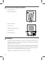
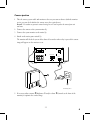
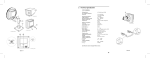
Electro Magnetic Compatibility (EMC)
This equipment complies with the European rules for EMC according to EN55013, EN55020
and EN50082-1.
The equipment conforms to the EMC directive and low-voltage directive.
This device complies with EMC rules under test conditions that included use of system cables
and connectors between system components. If you have any problems, contact your dealer.
English
Warning
Any unauthorized modification to this equipment may cause violation of the EMC rules
resulting in the revocation of the authorization to operate the equipment.
The exclamation mark within a triangle is intended to alert the user to the presence
of important operating and maintenance (servicing) instructions in the literature
accompanying the appliance.
Note: We advise you to use the following types of mains power adaptors in combination with the camera:
UK Philips VCM1162/01R
EUR Philips VCM1162/00R
g
English
g
2
English
Colour Observation Camera
Table of contents
Page
Introduction .......................................................................................................... 4
Connection and operation facilities................................................. 5
Installation ............................................................................................................. 5
Camera position
Focus adjustment
Back-focus adjustment
Camera sound on/off
Outdoor use
Using a different lens .................................................................................... 9
4mm/F1.2 lens
8mm/F1.2 lens
4mm/F1.2 auto-iris lens
8mm/F1.2 auto-iris lens
Changing a lens............................................................................................... 11
System cable...................................................................................................... 12
Tips for maintenance................................................................................. 12
Read these instructions, before taking your system in operation.
g
3
Introduction
This camera is especially designed for the Philips Observation System. It can be used in
combination with a system monitor (System, Quad or Slave). The System and Quad monitor
provides input for up to 4 cameras. The slave monitor can handle 1 camera in a stand-alone
configuration. The camera has a standard camera mount allowing installation on, for example, a
tripod or wall bracket.
Power supply:
The safe low voltage (16-32V _) for the camera and system accessory is supplied by the monitor
through the system cable. If the length of the system cable is more than 200m/600ft a mains
power adapter should be used to provide the camera power supply.
•
•
•
•
Camera accessories:
The following camera accessories are available:
Auto-iris lens 4mm (F1.2)
Auto-iris lens 8mm (F1.2)
Protective camera housing
Mains power adapter
g
4
Connection and operation facilities
Focus adjustment ring
2
Back-focus adjustment ring
R
< > NE
AR
FA
1
CL 66610005_310b.AI
Camera sound on/off
4
Auto-iris socket
5
Cable length compensation selector
6
System cable socket
7
External supply socket
3
2
100m
200m
24V
+
0
3
1
0X1
0-50m
4
7
300m
5
6
CL 66610005_311b.AI
Installation
This chapter describes the installation of the camera. For more detailed information about the
installation and operation of the system monitor and accessories (optional) you should consult
the monitor and/or accessory manuals.
Remark: When the system configuration is altered, the system monitor needs to check and memorise the
cameras and accessories connected to its inputs. This is done automatically when the power is switched on.
Use the power switch to switch off, only operating the power save key is not sufficient. If switching off is
impracticable, use the auto install option of the system monitor’s install menu.
Caution: Never touch the glass of the camera lens as this may cause damage.
g
5
Camera position
1
Take the camera, system cable and monitor to the area you want to observe (with the monitor
on site, you can check whether the camera covers the required area).
Remark: For outdoor use protective camera housing has to be used to protect the camera from rain
and snow.
2
Connect the camera to the system monitor (1).
3
Connect the system monitor to the mains (2).
4
Switch on the mains power switch (3).
The monitor will check the system. After about 30 seconds or when a key is pressed the camera
image will appear on the monitor screen.
slave
camera in
1
2
3
out
4
max 24V 2A
video
power
audio
in
out
VCR
out
aux
out
alarm gnd
3
1
2
CL 66610005_314A.AI
5
If necessary adjust contrast T/brightness ( and/or colour S (controls at the front of the
monitor) to optimise the camera image.
g
6
6
Hold the camera at the
proposed installation
position
7
Check on the monitor
whether the camera covers
the required area (The best
results are obtained when
the camera is pointed
slightly downwards and is
not looking into a bright
light source). Adjust focus
if necessary.
8
9
1/4" 20 UNC
3
1
Fasten the wall bracket (1)
to the wall, or another even
and firm surface.
2
CL 66610005_302.AI
Tighten the knob (2).
10 Fasten the camera to the bracket (3).
11 Loosen knob (4) and screw (5) slightly (figure below).
12 Direct the camera at the object or area you want to observe (8). Check the camera image on the
monitor. Adjust focus if necessary.
13 Tighten the knob (4) and screw (5) when the camera is in position.
8
5
7
100m
200m
24V
+
0
4
0X1
0-50m 300m
6
CL 66610005_303.AI
g
7
14 Check if the cable length compensation (6) selector is set to the correct length. The length set
must be the same as the length of the system cable (0-300m/900ft max.) connecting monitor
and camera.
Remark: If the length of the system cable is more than 200m/600ft, a mains power adapter (optional)
should be used (the max. allowed cable length is 300m/900ft). Connect the adaptor to the mains and to the
external supply socket (7) at the back of the camera.
Focus adjustment
1
•
Adjust the focus ring of the camera lens to obtain
optimal image sharpness.
Remark: If still no sharp object image is obtained, you
should adjust the back-focus of the camera.
R<
FA
> NEAR
Back-focus adjustment
•
•
•
•
•
Caution: Back-focus adjustment is only necessary when no
CL 66610005_304B.AI
sharp object image is obtained with the focus adjustment
ring.
Set focus adjustment ring to Far or Infinity (1).
Aim the camera at an object at least 15 metres/45 feet away.
Remark: When bright light sources are positioned within thecamera view field; dim the light source.
Loosen the back-focus locking ring (2).
Rotate the lens, including the CS-mount ring, until the video image on the monitor is sharp.
Tighten the back-focus locking ring (2), while keeping the lens in place.
2
1
R<
FA
> NEAR
3
CL 66610005_305.AI
g
8
Camera sound on/off
Use switch (9) to enable or disable the built-in camera
microphone.
Outdoor use
For outdoor use a protective cover has to be used to
protect the camera.
Remark: When the camera is used outdoors an auto-iris lens
is recommended.
9
On
Off
CL 66610005_306.AI
Using a different lens
The CS-mount of the camera allows you to use other lenses. The field of view (= covered area) of
an 8mm lens is half of the field of view of the 4mm lens (see figure below).
Lenses available are:
4mm/F1.2 lens
8mm/F1.2 lens
4mm/F1.2 auto-iris lens
8mm/F1.2 auto-iris lens
d
The cameras are supplied either with the 4mm
or 8mm lens.
10
4 mm
8
6
8 mm
4
2
0
0
2
4
6
8
Distance object to camera in meters (d)
10
Focal length of the lens
Horizontal field of view in meters (V)
The auto-iris lenses are recommended when the
camera is used in environments with variable
light conditions (eg. outdoors). By means of the
auto-iris the amount of light going through the
lens is regulated. The auto-iris is DC-controlled
through a 4-pole connector at the back of the
camera (3).
V
CL 66610005_308A.AI
g
9
The pin connections of the auto-iris
connector are:
pin 1 = control coil pin 2 = control coil +
pin 3 = drive coil pin 4 = drive coil +
42
All lenses have the same light sensitivity.
31
CL 66610005_309.AI
g
10
Changing a lens
•
•
R<
FA
Perform the following steps to change a lens:
Point the camera downwards. This to minimize possible deposit of dust on the inside of the
camera when the lens is removed.
1
Remove the old lens by turning it
counter-clockwise (1).
Do not release the back-focus locking ring (2),
otherwise you may have to readjust the
back-focus of the camera.
Caution: Never touch the CCD sensor which is
located at the inside of the camera. Only use clean,
dry air to blow particles from the surface of the sensor.
> NEAR
CL 66610005_312.AI
•
Mount the new lens by turning it clockwise
onto the lens mount of the camera.
6
1
4 3
R<
FA
> NEAR
5
CL 66610005_313.AI
•
•
•
Direct the camera at the object or area to be monitored (6).
Tighten the knob (3) and screw (4) when the camera is in position.
Adjust the focus ring (1) of the camera lens to obtain an optimal image sharpness.
Remark: If an auto-iris lens is used, connect the auto-iris cable to the camera (5).
g
11
2
System cable
For the interconnections between
the system monitor and camera
25m/75ft system cable is supplied.
For an optimum picture and sound
quality you should always use 4-wire
dual twisted-pair cable when
extending the connection. The max.
allowed cable length is 300m/900ft.
The cable and plugs are available in
the hobby and professional trade.
Pay attention that the connectors
are fixed to the cable corresponding
to the figure.
2 34 5
2 34 5
2
3
2
3
45
4-5
2-3
45
4-5
2-3
CL 66610005_006.AI
If the cable length between the monitor and camera is more than 200m/600ft a mains power
adapter should be used (see accessories).
Caution: The plugs used for the observation system have the same dimensions as standard telephone plugs.
Never connect a telephone to the camera or system monitor.
Tips for maintenance
Cleaning
You can clean the outside of the camera with a moist fluff-free cloth or shammy leather cloth.
When cleaning the camera lens a special cleaning cloth should be used. Do NOT use cleaning
fluids based on alcohol, methylated spirit, ammonia, etc..
Never touch the glass of the camera lens to prevent its delicate coating from damaging.
Avoid direct contact with water.
g
12
Technical specifications (VCM7177/00T / VCM7178/00T)
Pick-up element
Pixel elements
Resolution
Gain control
Lens
Iris
Light sensitivity
Scene illumination
Signal to noise ratio
White balance TTL
System connector (output)
•
Microphone
Frequency range
Synchronisation
Power supply
•
•
•
•
•
•
1/3" solid state CCD
512 (H) x 582 (V), PAL interlaced
330 TVL
automatic, 20dB
See: Using a different lens
Electronic iris
When connected, an auto-iris lens overrides the electronic iris.
• 0.4 lux minimally acceptable picture with standard lens (F1.2)
at 3200K, transmission 86%, scene reflection 100%
• 3.0 lux, 50ire (-6dB) with standard lens (F1.2) at 3200K,
transmission 86%, scene reflection 100%
Not for continuous use above 2k lux with standard lens (F1.2)
For outdoor use an auto-iris lens is recommended.
48dB at 200-25000 lux, 25°C
range 2500-6500K
audio: common mode 500mVpp
video: differential mode 175mVpp with pre-emphasis of 12dB at
5MHz. In the dual twisted pair system cable one pair carries the
audio signal and the videosignal, the other the power supply
and the synchronisation pulses.
Built-in, can be switched off at the camera.
300-3000Hz
The camera automatically synchronises to the system monitor.
Without system monitor the camera generates its own
synchronisation signals.
24VDC, when the system-cable length exceeds 200m/600ft a poweradapter (24VDC, current limit 500mA) is required (available asaccessory)
≤3W
max. 300m/900ft (when a mains power adaptor is used)
72,5 (H) x 70 (W) x 60 (D) mm (excl. lens)
190g
Power consumption
System-cable length
Dimensions
Weight
Connectors
System cable
RJ11E modular (“telephone” plug)
External power
Power jack
Auto-iris control
4-pole socket
Mounting
1/4" 20 UNC
Ambient temperature
Operating
-10 to +50°C
Storage
-25 to +70°C
Ambient humidity
Operating
20 to 90% RH
Storage
up to 99% RH
Specifications may change without notice.
124