1
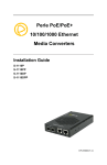
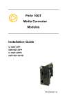
Perle SMI Media Converter
Installation Guide
P/N 5500316-13
Introduction
Perle SMI Media Converters provide seamless high-speed
managed integration of Ethernet to Fiber networks.
Overview
This guide contains instructions necessary for the
installation and operation of the Perle SMI Media Converter.
This Media Converter consists of the MCR200 chassis, a
MCR-MGT Management Module and one Media Converter
Module.
The fiber connection can be either single mode (SM) or
multimode (MM) and can operate over different wavelengths
and distances, depending on the model selected (see table
below).
100/110 Models
(xxx)
1000/1110 Models
(xxxx)
Connector
(cc)
Mode
Distance
Wavelength
(TX/RX)
SMI-xxx-M2cc02
SC/ST/LC
MM
2 km
1.2 mi.
1310 /1310 nm
SMI-xxx-S2cc20
SC/ST/LC
SM
20 km
12.4 mi.
1310/1310 nm
SMI-xxx-S1SC20U
SC
SM
20 km
12.4 mi.
1310/1550 nm
SMI-xxx-S1SC20D
SC
SM
20 km
12.4 mi.
1550/1310 nm
SC/ST/LC
SM
40 km
24.9 mi.
1310/1310 nm
SMI-xxx-S1SC40U
SC
SM
40 km
24.9 mi
1310/1550 nm
SMI-xxx-S1SC40D
SC
SM
40 km
24.9 mi
1550/1310 nm
SMI-xxx-S2cc80
SC/ST/LC
SM
80 km
49.7 mi
1550/1550 nm
SMI-xxx-S2cc120
SC/ST/LC
SM
120 km
74.6 mi
1550/1550 nm
SMI-xxxx-M2cc05
SC/ST/LC
MM
550 m
1804 ft.
850/850 nm
SMI-xxxx-M2cc2
SC/ST/LC
MM
2 km
1.2 mi.
1310/1310 nm
SMI-xxx-S2cc40
Perle SMI Media Converter Guide
2
100/110 Models
(xxx)
1000/1110 Models
(xxxx)
Connector
(cc)
Mode
Distance
Wavelength
(TX/RX)
SC/ST/LC
SM
10 km
6.2 mi.
1310/1310 nm
SMI-xxxx-S1SC10U
SC
SM
10 km
6.2 mi.
1310/1490 nm
SMI-xxxx-S1SC10D
SC
SM
10 km
6.2 mi.
1490/1310 nm
SMI-xxxx-S1SC20U
SC
SM
20 km
12.4 mi.
1310/1490 nm
SMI-xxxx-S1SC20D
SC
SM
20 km
12.4 mi.
1490/1310 nm
SC/ST/LC
SM
40 km
25 mi.
1310 /1310 nm
SMI-xxxx-S1SC40U
SC
SM
40 km
25 mi.
1310/1490 nm
SMI-xxxx-S1SC40D
SC
SM
40 km
25 mi.
1490/1310 nm
SC/ST/LC
SM
70 km
43.5 mi.
1550/1550 nm
SMI-xxxx-S1SC80U
SC
SM
80 km
50 mi.
1510/1590 nm
SMI-xxxx-S1SC80D
SC
SM
80 km
50 mi.
1590/1510 nm
SMI-xxxx-S2cc120
SC/ST/LC
SM
120 km
74.6 mi.
1550/1550 nm
SMI-xxxx-S1SC120U
SC
SM
120 km
74.6 mi.
1510/1590 nm
SMI-xxxx-S1SC120D
SC
SM
120 km
74.6 mi.
1590/1510 nm
SC/ST/LC
SM
160 km
100 mi.
1550/1550 nm
SPF
Note 1
Note 1
SMI-xxxx-S2cc10
SMI-xxxx-S2cc40
SMI-xxxx-S2cc70
SMI-xxxx-S2cc160
SMI-xxxx-SFP
Please visit Perle’s web site for the most up to date
Installation guides, models and specifications:
http://www.perle.com/
Perle SMI Media Converter Guide
3
Getting to know your SMI Media
Converter
Unpacking your SMI Media Converter
Your SMI Media Converter consists of the following items:
A MCR-MGT Management card
•
See section in this guide for setting up your MCR-MGT
Management Module
Media Converter module
•
See enclosed Media Converter Installation guide for
usage and features for your module. These may include
Link Mode, Fiber Fault Alerts, Loopback and more.
SMI chassis
•
Two slot chassis
Other Components
•
Grounding screws (for improved chassis grounding)
•
Country specific power adapter
•
Power cord strain relief clip
•
Four rubber feet
•
User installation guide for the Media Converter Module
•
CDROM including firmware for the MCR-MGT
Management Module and Media Modules, MCR-MGT
Management module User guide and MCR-MGT
Management module CLI guide.
•
This guide
Perle SMI Media Converter Guide
4
Front and Rear Panel Components
Front View
Rear View
Perle SMI Media Converter Guide
5
Installation
These steps are needed to get fiber connectivity.
1. Connect the fiber cable.
2. Connect the copper cables.
3. Power up the SMI Media Converter.
4. Both the power led indicator lights on the MCR-MGT
management module and the media module should be
illuminated. (Refer to the product guide that came with
your SMI Media Converter for individual LED definitions).
Powering up the SMI Media Converter
Note: The SMI Chassis should always be grounded for safe and
proper operation. See Grounding the SMI Chassis
1. Using the Perle supplied power adapter, plug the power
cord into the power cord connector at the rear of the
chassis.
2. Plug the other end of the power adapter into an
appropriate power outlet.
See the media converter module guide that came with your
SMI Media Converter to access media converter module
features:
•
LEDs
•
DIP switch settings
•
Jumper settings
Adding or Removing Modules:
The Media Converter Module may need to be removed for
setting jumpers or DIP switches, if the defaults are not
Perle SMI Media Converter Guide
6
appropriate. Also, either module can be removed should
servicing be required.
Caution: Observe electrostatic discharge precautions when
installing or removing the Module(s) from the Chassis.
Failure to observe this caution could result in damage to the
Module(s) and/or chassis.
1. Loosen the Captive retainer screw on the front of the
module.
2. Gently pull the module towards you.
3. Set any jumpers and/or DIP switches on the Module to
the desired operating mode. (Refer to the product guides
that came with your SMI Media Converter).
4. Gently slide the module back into the slot until it
becomes flush with the front of the chassis. Light
pressure may be needed to seat the module. Do not
force the module as you might damage the module. If
there is resistance, remove the module and check the
module’s backplane connector for damage to the pins. If
the module’s backplane connector is not damaged, try to
reinsert the module again
5. Tighten the Captive retainer screw to ensure the module
is locked in place.
Perle SMI Media Converter Guide
7
Grounding the SMI Chassis (Optional)
If your installation requires additional grounding the following
procedure can be followed.
Grounding the chassis requires the following items:
•
One grounding lug (not provided)
•
One 18 - 12 AWG wire (not provided)
•
Cross-head screwdriver (not provided)
Note: For your safety, when installing this equipment, always
ensure that the chassis ground connection is installed first
and disconnected last.
Attaching the Grounding Lug
1. Attach the grounding lug to one end of an 18-12 AWG
wire.
2. Attach the grounding lug to the chassis and secure with
the grounding screw(s).
Attaching the Power Cord Strain Relief Clip
1. Feed the power cord through the opening in the power
cord relief clip.
Perle SMI Media Converter Guide
8
2. Attach the power cord relief clip to the chassis and
secure with the provided screw.
3. Plug the power cord into the AC power connector at the
rear of the chassis.
4. Plug the other end of the power cord into an appropriate
power outlet.
Perle SMI Media Converter Guide
9
MCR-MGT Management Module
Your SMI Media Converter comes with a powerful MCRMGT Management Module that allows you to configure,
monitor and control your SMI Media Converter.
Features
•
Management access through AAA security such as
RADIUS, TACACS+, LDAP, Kerberos and NIS.
•
IPv4 and IPv6 network environments.
•
Central management and configuration through SNMPv3
as well as SNMPv1/2.
•
Management module access via Browser, Telnet or SSH
over 10/100/1000 Mbps Ethernet.
•
Cisco pin-compatible RJ-45 console port on
Management module for easy cabling connections.
•
Local Event logging and Syslog
•
Quickly restore manufacturing configuration settings.
Making Connections to the
Management Module
Connecting To The LAN
Depending on the speed at which you plan to operate your
Ethernet connection, locate compliant copper cables with
male, RJ-45 connectors installed at both ends.
Connect the RJ-45 cable between the MCR-MGT Ethernet
port and the hub or switch port which will connect the
module to your Ethernet LAN.
Note: The MCR-MGT module supports Auto MDI/MDIX detection
which allows for the use of a straight-through or cross-over
Ethernet cable.
Perle SMI Media Converter Guide
10
Connecting To The Console Port
This is a serial connection. It will allow you to connect a
terminal or PC with terminal emulation software to the
console port of the Management module.
The following is the cable pinout required to connect the
console port to a DB-9 port on the PC.
PC
MCR-MGT
Management Module
DB9 serial
RJ-45 Console Port
8 (CTS)
1 (RTS)
6 (DSR)
2 (DTR)
2 (RxD)
3 (TxD)
5 (GND)
5 (GND)
3 (TxD)
6 (RxD)
4 (DTR)
7 (DSR)
7 (RTS)
8 (CTS)
Alternately, you can purchase the following two parts from
Perle Systems Limited.
•
3ft RJ-45 straight through cable. Part #:04005120
•
RJ-45 to DB9F-DTE (console adapter). Part #:04007040
Perle SMI Media Converter Guide
11
Configuring the Management-MGT
Module
There are a number of methods which may be used to
configure the MCR-MGT management module:
•
Command Line or Menu interface via a direct serial
connection to the console port
•
Command Line or Menu interface via Telnet or SSH to
module
•
SNMP
•
Web Browser (HTTP or HTTPS)
All of the above methods require you to configure an IP
address on the management card to be able to connect and
configure the module except for the direct serial connection
which you can connect directly to the console port. The
management module is pre-configured with an IP address of
10.0.0.10 with a subnet mask of 255.0.0.0. If the PC that
you are using does not reside on this subnet, you will need
to modify either the IP address of the MCR-MGT
management module (using a direct serial connection to the
Management module) or the pc’s IP address in order to
connect and configure the Management module.
The following are two methods in which to set the IP
address of the MCR-MGT Management module.
Perle SetIP Utility
On the CD provided with the MCR-MGT module, you will
find an executable called “Perle SetIP”. You can run it
directly from the CD or copy it to your local PC drive and
execute it from there.
When the program runs, you can do the following;
1. From the list of devices displayed, click on the MCRMGT module you wish to set the IP address on and then
Perle SMI Media Converter Guide
12
click on the “Assign IP” button at the top of the screen.
Please note that this operation will only be valid on
MCR-MGT modules which are in a “factory default”
state.
2. To manually assign the IP address, click on “Assign IP
manually”, key in the desired IP address and press the
“Assign IP” button. If a DHCP server is available on this
subnet, you can choose to have the module obtain its IP
address via your DHCP server by clicking on the “Assign
IP using DHCP” button and then pressing the “Assign IP”
button.
3. For modules which have been assigned IP address, you
can click on the “manage” button on the top of the
screen to launch a web browser session with the
selected MCR-MGT module. You can achieve the same
result by manually launching your web browser and
entering the IP address of the module in the web
browsers address field.
4. You can also use Telnet, SSH or SNMP to configure the
module.
Serial Console Port
Using the proper cable connector, connect the Management
module to the serial port on your PC. Perle Systems has
available for purchase an RJ-45 to DB9F-DTE console
adapter (part #04007040) which can be used in conjunction
with an RJ-45 patch cable (part #04005120) to connect your
PC’s serial port to the Management module’s console port.
Set the communication parameters on your PC’s terminal
emulation program to 9600,8,n,1.
1. Press [Enter]. The management module prompt will
appear.
Perle SMI Media Converter Guide
13
2. Type set server internet <IPv4 address>netmask
<mask>[Enter]
Example:
set server internet 196.12.10.9 netmask
255.255.255.0[Enter]
1. Type save [Enter]
2. When prompted “Save config to flash ROM y/n” [Enter]
3. Type reboot [Enter]
4. When prompted “Confirm reboot unit y/n [Enter]
5. When the Management module reboots, the IP address
you entered will be active. You can now use your
favourite web browser to configure the module. Simply
enter the IP address in the web browsers address field
and press [Enter].
6. You can also use Telnet, SSH or SNMP to configure the
Management module.
Resetting the MCR-MGT Management Module To
Factory Default Settings
If it becomes necessary to return the Management module
to the factory default settings, press and hold the “RESET”
button on the front of the module for 3 seconds (you can use
a paper clip to do this). This will return the configuration to
the factory default settings and will force the module to
reboot.
Perle SMI Media Converter Guide
14
LED Status for the Management
Module
The MCR-MGT module has four status LEDs, which are
used to monitor the operational status of the MCR-MGT
Module in the network and the status of the MCR1900
Chassis.
ALM - Alarm
Off - No faults detected.
Red - A severe or critical level fault has been detected in the
system.
PWR - Power
Green - Power is on and the module is in normal operation
mode.
Green blinking - The MCR-MGT Module is initializing. The
bootup should complete within 1 minute, at which time the
PWR LED should go solid green.
Off - The MCR-MGT module has no power.
Red - Unrecoverable hardware error on MCR-MGT module.
Perle SMI Media Converter Guide
15
LKC - Copper –Link/Activity
On - Copper link is up.
Off - Copper link is down.
Blinking (quickly) - Copper link is up and is sending or
receiving data.
100/1000
Green - The Ethernet speed on the management module is
detected at 1000 Mbps (Gigabit).
Yellow - The Ethernet speed on the management module is
detected at 100 Mbps.
Off - The Ethernet speed on the management module is
detected at 10 Mbps
Perle SMI Media Converter Guide
16
Troubleshooting
General
•
Ensure power is supplied to the Media Converter – use
of the supplied power adapter is highly recommended.
•
Ensure that the Media Converter Module and MCR-MGT
Management Module are securely seated in the chassis
See Adding or Removing Modules.
•
Ensure both devices on either end of the fiber are
compatible. If using a simplex fiber connection, ensure
that you have both an Upstream (U) and Downstream
(D) Media Converter.
•
Ensure all cabling is of the correct type and is in good
working order.
•
For duplex fiber connections, ensure the RX and TX has
been reversed between the two Media Converters.
No connectivity
Refer to the media converter guide that came with your SMI
Media Converter.
Loopback Mode
The fiber connection can also be verified by configuring the
SMI Media Converter for loopback mode. Refer to the Media
converter guide that came with your SMI Media Converter
for DIP switch setup.
MCR-MGT “PWR” LED is OFF
Ensure that the management module is inserted into the
chassis correctly. See Adding or Removing Modules.
Ensure that the MCR Chassis is connected to an external
power source.
Perle SMI Media Converter Guide
17
MCR-MGT “PWR” LED is RED
The MCR-MGT module is defective. It will need to be
replaced.
MCR-MGT “PWR” LED is Blinking Green
The MCR-MGT module is in the process of booting up. If this
state persists for longer then one minute, reset the module by
momentarily pressing the reset switch on the front of the module.
See Front view – reset switch.
Cannot connect serially to MCR-MGT Module
1. Make sure that the PWR LED is “Green”
2. Ensure that you are using the right cable/adapter.
3. If you see garbage characters, the baud rate of the serial
port may have been changed from the original 9600
baud. Configure your terminal emulation to match
configured speed.
4. If you don’t know what the speed is, you could reset the
module to “factory default” by pressing and holding the
reset switch (3 seconds) on the front of the MCR-MGT
module. NOTE: this will erase the entire configuration
back to a factory default state.
Cannot connect to MCR-MGT Module using an IP
address
1. Make sure that the PWR LED is “Green”
2. Make sure that the LKC LED is “Green”. (Copper link
connection is up).
3. Make sure you are using the IP address which is
configured on the MCR-MGT module.
Perle SMI Media Converter Guide
18
4. If you don’t know what the IP address is, you can use
the “SetIP” utility provided on the CD to display the IP
address of all units on your LAN segment.
Perle SMI Media Converter Guide
19
Technical Specifications for the SMI Media
Converter
The following applies to all SMI-xxxx Media Converters:
Max Power Input/Consumption: 12 V DC/15 Watts
Operating Temperature:
0°C - 50°C (32°F - 122°F)
Storage Temperature:
-25°C - 70°C (-13°F - 158°F)
Operating Humidity:
5% to 90% non-condensing
Storage Humidity:
5% to 95% non-condensing
Operating Altitude:
Up to 3,048 m (10,000 ft)
Weight without cards:
0.566 kg (1.25 Lbs.)
Weight with cards:
0.722 kg (1.59 Lbs.)
Dimensions
175 mm 145 mm by 23 m
6.9” in. by 5.7” in. by .90” in.
MTBF (Hours)
excluding
Power
adapter
MTBF (Hours)
including
Power
adapter
0.42 amps
248,259
169,698
4.98 watts
0.42 amps
268,167
178,770
SMI-1110
4.1 watts
0.34 amps
238,087
164,883
SMI-1110-SFP
4.1 watts
0.34 amps
256,533
173,524
SMI-100
3.98 watts
0.33 amps
245,769
168,532
SMI-110
4.1 watts
0.34 amps
246,403
168,829
Model
Power
Consumption
SMI-1000
4.98 watts
SMI-1000-SFP
Current
(@ 12 V DC)
Perle SMI Media Converter Guide
20
Ethernet Copper Cabling
Category 5 UTP or STP
24-22 AWG Straight through or Ethernet crossover
Console Port Cabling Requirements
Pinout
Console Port
1
RTS (out)
2
DTR (out)
3
TxD (out)
4
GND
5
GND
6
RxD
7
DSR (in)
8
CTS (in)
Note: Please refer to the product page on the Perle website
for the most up to date specifications.
http://www.perle.com/
Perle SMI Media Converter Guide
21
Compliance Information
FCC
This product has been found to comply with the limits for a Class A digital device,
pursuant to Part 15 of the FCC rules. These limits are designed to provide
reasonable protection against harmful interference when the equipment is operated
in a commercial environment. This equipment generates, uses, and can radiate
radio frequency energy and, if not installed and used in accordance with the
instructions in this Guide, may cause harmful interference to radio communications.
Operation of this equipment in a residential area is likely to cause harmful
interference, in which case the user will be required to correct the interference at
his/her own expense.
EN 55022 Class A
WARNING This is a Class A product. In a domestic environment this product may
cause radio interference in which case the user may be required to take adequate
measures.
EN 55024 Class A
Laser Safety – IEC 60825-1:2007
This product meets Class I Laser safety requirements per IEC-60825-1:2007
standard and complies with FDA/CDRH 21 CFR1040.10 and 21 CFR1040.11.
WARNING: Visible and invisible laser radiation may be present when cables are
not connected. Do not stare into the beam or view the beam directly with optical
instruments. Failure to observe this warning could result in an eye injury or
blindness.
WARNING: Use of controls, adjustments or the performance of procedures other
than those specified herein may result in hazardous radiation exposure.
Perle SMI Media Converter Guide
22
Warranty / Registration
Perle’s Systems Ltd. standard Lifetime Warranty provides
customers with return to factory repairs for Perle products
that fail under the conditions of the warranty coverage.
Details can be found at:
http://www.perle.com/support_services/warranty.shtml
Contacting Technical Support
Contact information for the Perle Technical Assistance
Center (PTAC) can be found at the link below. A Technical
Support Query may be made via this web page.
www.perle.com/support_services/support_request.shtml
Copyright
© 2011 Perle Systems Limited
All rights reserved. No part of this document may be reproduced or used in any
form without written permission from Perle Systems.
Perle SMI Media Converter Guide
23