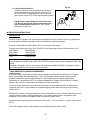
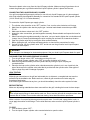
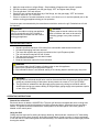
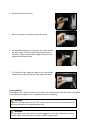
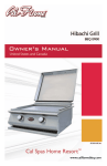
1
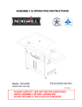
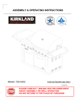
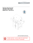
ITEM / ARTICLE / ARTICULO # 271573
STAINLESS STEEL LP GAS GRILL
GRIL AU GAZ PL EN ACIER
INOXYDABLE (page 29)
PARRILLA A GAS PL DE ACERO
INOXIDABLE (página 57)
MODEL / MODÈLE / MODELO # 720-0522
TM
TM
WARNING
To reduce the risk of fire, burn hazard or
other injury, read the Care and Use
Manual carefully and completely before
using your grill.
WARNING
FOR OUTDOOR USE ONLY
®
WARNING
This grill is not intended to be
installed in or on recreational
vehicles and/or boats.
Example only: SERIAL # ________ MFG. DATE ________ PURCHASE DATE: _________ H20Y07P-4
Questions, problems, missing parts? Before returning to your retailer, call our customer
service department at 1-877-323-5263, 8 a.m. - 6 p.m., PST, Monday - Friday, 8 a.m. – 12 p.m.
Saturday.
TABLE OF CONTENTS
Safety Information….…………………………………………………....………………...……..….3
Package Contents List………………………………………………………………………..……..7
Preparation……………….…………………. ……………………….…………….………………..8
Assembly Instructions…………………………………………………………….…..……..………8
Installation Instructions…………………………………………………………….....…….……...15
Operation Instructions…….…………………………………………………….…..…..……….…17
Care and Maintenance……………………………………………………………………………..22
Troubleshooting…………………………………………………………………..……….………..24
Warranty………………………………….…………………………………………..………..…….25
Replacement Parts List………………….…...……………………………………..…….……….26
WARNING
WARNING
If you smell gas:
1. Shut off gas to the appliance.
2. Extinguish any open flame.
3. Open lid.
4. If the odor continues, keep away from the
appliance and immediately call your gas supplier
or local fire department.
1. Do not store or use gasoline or other
flammable vapors and liquids in the vicinity
of this or any other appliance.
2.
2
A Liquid Propane cylinder not in use
should not be stored in the vicinity of this or
any other appliance.
SAFETY INFORMATION
Please read and understand this entire manual before attempting to assemble, operate or install the product. If you have any
questions regarding the product please call customer service at 1-877-323-5263, 8 a.m. - 6 p.m., PST, Monday Friday, 8 a.m. – 12 p.m. on Saturday.
1. Safety Symbols
WARNING – Hazardous or unsafe practices which could result in severe personal injury or death.
CAUTION – Hazardous or unsafe practices which could result in minor personal injury.
2. Do not try lighting this appliance without first reading the “LIGHTING INSTRUCTIONS” section on
page 18 of this manual.
3. Never attempt to use damaged or obstructed equipment. See your local Liquid Propane dealer for
repair.
4. Check all gas supply fittings for leaks before each use. Do not use the grill until all connections have
been checked and do not leak. Do not smoke while leak testing. Never leak test with an open flame.
5. Do not store or use gasoline or other flammable vapors and liquids in the vicinity of this or any other
appliance.
6. A Liquid Propane cylinder not in use should not be stored in the vicinity of this or any other appliance.
7. When lighting, keep your face and hands as far away from the grill as possible.
8. Storage of an outdoor cooking gas appliance indoors is permissible only if the Liquid Propane cylinder
is disconnected and removed from the outdoor cooking gas appliance.
9. Failure to properly place the burner over the orifice could cause a fire to occur behind and beneath the
valve panel, thereby damaging the grill and making it unsafe to operate.
10. Do not leave the grill unattended while cooking.
11. Liquid Propane cylinder must be stored outdoors and out of the reach of children and must not be
stored in a building, garage, or any other enclosed area.
12. This grill is not intended to be installed in or on recreational vehicles and / or boats.
13. Do not install this unit into combustible enclosures. There should be a minimum clearance of 24
inches from all sides to combustible materials.
14. Outdoor cooking appliance shall not be used under overhead combustible construction.
15. A Liquid Propane cylinder of approximately 12 inches in diameter by 18 1/2 inches high is the
maximum size to use. You must use an OPD Liquid Propane cylinder, which offers an Overfill
Prevention Device.
16. Keep the rotisserie motor electric cord away from the heated surfaces of the grill. When not in use,
remove and store the motor in a dry location.
17. Keep the electrical supply cords and fuel supply hoses away from any heated surfaces.
18. Spiders and insects can nest inside the burners of the grill and disrupt gas flow. Inspect the grill at
least twice a year.
19. The grill and its individual shut-off valve must be disconnected from the gas supply piping system
during any pressure testing of that system at test pressure in excess of 1/2 inch psi. (3.5 kpa).
20. The grill must be isolated from the gas supply piping system by closing its individual manual shut-off
valve during any pressure testing of the gas supply piping system at test pressure equal to or less than
1/2 inch psi. (3.5 kpa).
WARNING
Spiders and insects can nest inside the burners of the grill and disrupt gas flow. This very
dangerous condition could cause a fire behind the valve panel, thereby damaging the grill and
making it unsafe for operation. Inspect the grill at least twice a year.
3
WARNING
Do not use the grill if the odor of gas is present. Contact customer service at 1-877-323-5263.
CAUTION
1. The grill head is heavy and will require two or more people to lift and position onto grill cart.
2. Before cleaning, make sure the gas supply and control knobs are in the “OFF” position and the
burners have cooled.
3. When using a match to light the grill make sure to use the attached lighting rod.
4. When using the rotisserie burner, remove the warming rack. High heat from the rotisserie burner may
cause the warming rack to bend.
5. Do not alter the grill in any manner.
6. Clean and inspect hoses before each use. If there is evidence of abrasion, wear, cuts or leaks, the
hose must be replaced prior to operation. The replacement hose should be in accordance with the
manufacturer’s specifications.
BEFORE LIGHTING
Inspect the gas supply hoses prior to turning on the gas. If there is evidence of cuts, wear, or abrasion, it
must be replaced prior to use.
Use the pressure regulator and hose assembly supplied with the grill. Never substitute regulators for those
supplied with the grill. Contact customer service for proper replacement parts.
Install the regulator (type QCC1) onto the cylinder. Leak test the hose and regulator connections with a 1
part soap and 1 part water solution before operating the grill (See “Leak Testing” instructions on page 16).
Do not turn “ON” the gas at the Liquid Propane cylinder unless all gas hoses are properly connected and all
burner valves are in the “OFF” position.
WARNING
Do not try lighting this appliance without first reading the “LIGHTING INSTRUCTIONS” section
of this manual.
INFRARED SEARING SIDE BURNER
Inspect the gas supply hose prior to turning on the gas. If there is evidence of cuts, wear or
abrasion, it must be replaced prior to use. Do not use the side burner if gas odor is present.
Keep a spray bottle of soapy water near the grill and check the gas connections before each
use.
ROTISSERIE DRIVE MOTOR
To ensure continued protection against electric shock:
Connect to properly grounded outlets only.
Keep extension cord connections dry and off the ground.
Do not expose to rain.
Do not use indoors.
4
WARNING
Electrical Grounding Instructions for Rotisserie Motor – This appliance (rotisserie motor) is
equipped with a plug and should be plugged directly into a properly grounded receptacle. When
installed, must be electrically grounded in accordance with local codes or in the absence of local codes,
with the National Electrical Code, ANSI/NFPA 70 or the Canadian Electrical Code, CSA C22.1. DO
NOT cut or remove the grounding prong from this plug.
1. To protect against electrical shock, do not immerse cord or plugs in water or other liquids.
2. Unplug from the outlet when not in use and before cleaning. Allow to cool before putting on or
taking off parts.
3. Do not operate any outdoor cooking gas appliance with a damaged cord, plug, or after the
appliance malfunctions or has been damaged in any manner. Contact the manufacturer for repair.
4. Do not let the cord hang over the edge of a table of touch hot surface.
5. Do not use an outdoor cooking gas appliance for purposed other than intended.
6. When connecting, first connect plug to the outdoor cooking gas appliance then plug appliance into
the outlet.
7. Use only a Ground Fault Interrupt (GFI) protected circuit with this outdoor cooking gas appliance.
8. Never remove the grounding plug or use with an adapter of 2 prongs.
9. Use only extension cords with 3 prong grounding plug, rated for the power of the equipments, and
approved for outdoor use with a W-A marking.
TESTED IN ACCORDANCE WITH ANSI
Z21.58b LATEST STANDARD and CSA 1.6b2005 STANDARD FOR OUTDOOR COOKING
GAS APPLIANCES. THIS GRILL IS FOR
OUTDOOR USE ONLY.
Check your local building codes for the proper
method of installation. In the absence of local
codes, with either the National Fuel Gas Code,
ANSI Z223.1/NFPA 54, or CSA B149.1, Natural
Gas and propane Installation Code. Electrical
Code, ANSI/NFPA 70.
CCALIFORNIA PROPOSITION 65-WARNING
The burning of gas fuel generates some byproducts, which are known by the State of
California to cause cancer or reproductive harm.
To minimize exposure to these substances,
always operate this unit according to the care and
use manual, ensuring you provide good ventilation
when cooking with gas.
SAFETY PRACTICES TO AVOID INJURY
When properly cared for, your grill will provide safe, reliable service for many years. However, extreme
care must be used as the grill produces intense heat that can increase accident potential.
When using this appliance basic safety practices must be followed, including the following:
•
•
•
•
•
•
•
•
Do not repair or replace any part of the grill unless specifically recommended in this manual. All
other service should be referred to a qualified technician.
The grill is for outdoor use only.
Children should not be left alone or unattended in an area where the grill is being used. Do not
allow children to sit, stand or play on or around the grill at any time.
Do not store items of interest to children around or below the grill or cart. Do not allow children to
crawl inside the cart.
Never let clothing, pot holders or other flammable materials come in contact with or too close to
any grate, burner or hot surface until it has cooled. The fabric could ignite, causing serious
personal injury.
For personal safety, wear proper apparel. Loose fitting garments or sleeves should never be worn
while using this appliance. Some synthetic fabrics are highly flammable and should not be worn
while cooking.
Only certain types of glass, ceramic, earthenware, or other glazed utensils are suitable for grill
use. Other types of materials may shatter with sudden temperature changes. Use only low or
medium heat settings in accordance with the manufacturer’s guidelines.
Do not heat unopened food containers as a build-up of pressure may cause the containers to
burst.
5
•
•
•
•
•
•
•
•
•
•
•
•
•
•
•
•
•
•
•
•
•
•
•
•
Use a covered hand when opening the grill lid. Never lean over an open grill.
When lighting a burner, always pay close attention to what you are doing. Make certain you are
aware of which burner you are lighting so that your body and clothing remain clear of open
flames.
When using the grill, do not touch the grill rack, burner grate or immediate surroundings as these
areas become extremely hot and could cause burns. Use only dry potholders. Moist or damp
potholders on hot surfaces may cause steam burns. Do not use a towel or bulky cloth in place of
potholders. Do not allow potholders to touch hot portions of the grill rack.
Grease is flammable. Let hot grease cool before attempting to handle it. Do not allow grease
deposits to collect in the grease box, clean often.
Do not use aluminum foil to line the grill racks or grill bottom. This can severely upset combustion
air flow or trap excessive heat in the firebox area.
For proper lighting and performance of the burners, keep the burner ports clean. It is necessary to
clean them periodically for optimum performance. The burners will only operate in one position
and must be mounted correctly for safe operation. (See “Care and Maintenance” instructions on
page 22.)
Clean the grill with caution. To avoid steam burns, do not use a wet sponge or cloth to clean the
grill while it is hot. Some cleaners produce noxious fumes or can ignite if applied to a hot surface.
Never use a dented or rusty propane cylinder.
Turn all control knobs “OFF” and make certain the grill is cool before using any type of aerosol
cleaner on or around it. The chemical that produces the spraying action could, in the presence of
heat, ignite or cause metal parts to corrode.
Do not use the grill to cook excessively fatty meats or other products that promote flare-ups.
Do not operate the grill under unprotected combustible constructions. Use only in well ventilated
areas. Do not use in buildings, garages, sheds, breezeways or other such enclosed areas.
Keep the areas surrounding the grill free from combustible materials including, fluids, trash, and
vapors such as gasoline or charcoal lighter fluid. Do not obstruct the flow of combustion and
ventilation air. If the unit is stored indoors, make sure it is cool.
Do not use briquettes of any kind in the grill. The 720-0522 Liquid Propane grill is designed for
optimum performance without the use of briquettes. Do not place briquettes on the flame tamers,
as this will block the vent to the grill burners. Adding briquettes can damage ignition components
thus voiding the warranty.
Keep the back of the cart free and clear from debris.
Keep electrical supply cords and the rotisserie motor cord away from heated areas of the grill.
Never use the grill in extremely windy conditions. If located in a consistently windy area
(oceanfront, mountaintop, etc.), a windbreak will be required. Always adhere to the clearance
specifications.
Never attempt to use damaged or obstructed equipment. See your local Liquid Propane dealer for
repair.
Liquid Propane cylinder must be stored outdoors out of reach of children and must not be stored
in a building, garage or any other enclosed area.
Liquid Propane CYLINDER WARNING
Do not store or use gasoline or other flammable vapors and liquids in the vicinity of this or
any other appliance.
A Liquid Propane cylinder not connected for use should not be stored in the vicinity of this
or any other appliance.
Do not store spare Liquid Propane cylinders under or near this appliance.
Never fill the cylinder beyond 80 percent capacity.
Liquid Propane cylinders must be fitted with an Overfill Protection Device (OPD).
If the information above is not followed exactly, a fire resulting in death or serious injury
could occur.
6
PLACEMENT OF THE GRILL
WARNING
Do not install this unit into combustible enclosures. There should be a minimum clearance of 24 inches
from all sides to combustible materials.
Outdoor cooking appliances should not be used under overhead combustible construction.
When determining a suitable location take into account concerns such as exposure to wind, proximity to
traffic paths, and keeping gas supply lines as short as possible.
Place the grill in well-ventilated areas. Never place the grill in a building, garage, breezeway, shed or
other such enclosed areas. During heavy use, the grill will produce a lot of smoke.
PACKAGE CONTENTS LIST
A. Body Assembly -----------1pc.
B. Bottom Panel----------1 pc.
C. Door---------------2pcs.
D. Side Burner Shelf----------1pc.
E. Left Side Shelf------------1pc.
F. Left Side Panel----------1pc.
G. Right Side Panel----------1pc.
H. Back Panel---------------1pc.
I. Cart Frame--------------1pc.
TM
TM
7
HARDWARE CONTENTS
Pack
A
B
C
D
E
F
G
Description
5/32-in. x 10-mm Truss Head Screw
5/32-in. Locking Washer
1/4-in. x 15-mm Truss Head Screw
1/4-in. Locking Washer
5/32-in. x 15-mm Ladder Bolt
Lighting Rod
Battery / AAA
Quantity
24 pcs.
24 pcs.
45 pcs.
45 pcs.
1 pc.
1 pc.
1 pc.
A
B
C
D
F
E
G
PREPARATION
Before beginning assembly, installation or operation of product, make sure all parts are present. Compare
parts with package contents list and diagram above. If any part is missing or damaged, do not attempt to
assemble, install or operate the product. Contact customer service for replacement parts.
•
Estimated Assembly Time: 50 minutes
•
Tools Required for Assembly: Phillips Screwdriver (not included) and Wrench (not included)
ASSEMBLY INSTRUCTIONS
Fig. 1
1. Caster Assembly
Mount the casters onto the bottom panel (A) using sixteen
1/4-in. x 15-mm truss head screws from pack C and sixteen
1/4-in. locking washers from pack D.
The swivel caster with brake should be positioned under the
left rear of the cart bottom and the swivel caster should be
positioned under left front (C) as shown in fig. 1. The two
stationary casters (B) should be positioned under the right
side.
A
C
(1-2) B
8
Fig. 2
2. Side Panel Assembly
Loosen, but do not remove, the six 1/4-in. x 15-mm truss
head screws on the bottom panel (A) as shown in fig. 2.
Insert the screw and locking washer into the keyhole slot
located on the bottom of the left side panel (B). Position the
left side panel flush with the rear of the bottom panel and
tighten the screws.
B
C
Repeat steps for the right side panel (C).
A
Fig. 3
3. Back Panel Assembly
Remove the back panel from the carton. Position the back
panel (A) with the flat side facing outward. Attach the back
panel to the bottom panel (B) with three 1/4-in. x 15-mm truss
head screws from pack C and three 1/4-in. locking washers
from pack D as shown in fig. 3.
A
B
Fig. 4
Back and Side Panel Assembly
Use four 1/4-in. x 15-mm truss head screws from pack C and
four 1/4-in. locking washer from pack D to connect the back
panel (A) to the right and left side panels (B) as shown in fig. 4.
A
B
9
Fig. 5
4. Transformer Box Assembly
Align the holes of the transformer box (A) with the holes on the
back panel (B). Attach the transformer (A) to the back panel (B)
using six 5/32-in. x 10-mm truss head screws from pack A and
six 5/32-in. locking washers from pack B as shown in fig. 5.
B
A
C
The power cord bracket (C) connects to the rear cart panel
using two 5/32-in. x 10-mm truss head screws from pack A and
two 5/32-in. locking washers from pack B as shown in fig.5.
Fig. 6
5. Spare Liquid Propane Tank Barrier Bar Assembly
Attach the barrier bar (A) to the bottom panel (B) and back
panel (C) using two 5/32-in. x 10-mm truss head screws from
pack A and two 5/32-in. locking washers from pack B as shown
in fig. 6.
C
A
B
Fig. 7
6. Cart Frame Assembly
Remove the cart frame from the carton (A). Attach the
cart frame (A) to the side panels (B) using four 1/4-in. x
15-mm truss head screws from pack C and four 1/4-in.
locking washers from pack D as shown in fig. 7.
Note: Hinge bracket slot will need to be facing upwards.
A
B
10
Fig. 8
7. Door Assembly
Insert hinge pin on bottom panel into hole located on
bottom of door (A). Insert door hinge bracket
into the cart frame (B) and align with the hole in the top
of the door. Attach the door hinge brackets to the cart
frame with four 5/32-in. x 10-mm truss head screws from
pack A and four 5/32-in. locking washers from pack B as
shown in fig. 8.
B
A
Fig. 9
8. Liquid Propane Tank Heat Shield Assembly
Attach the heat shield (A) to the back panel (B) and
cart frame(C) using four 5/32-in. x 10-mm truss head
screws from pack A and four 5/32-in. locking washers
from pack B as shown in fig. 9.
B
A
C
Fig. 10
A
9. Firebox Assembly
Remove the firebox assembly (A) from the carton
and carefully place onto the grill cart (B). Note: Take care
when moving the firebox assembly as the bottom flanges can
be bent thus causing the holes not to align.
TM
TM
Connect the small wire (C) that extends from the transformer
box to the wiring junction box (D) located above the left panel
near the rear of the cabinet as shown in fig. 10 exploded view.
D
C
CAUTION The firebox assembly is heavy and will
require two or more people to lift and position onto grill
cart. Failure to do so may result in back injury.
B
11
Fig. 11
A
Attach the firebox assembly (A) to the grill cart (B) using four
1/4-in. x 15-mm truss head screws from pack C and four 1/4in. locking washers from pack D as shown in fig. 11.
B
Fig. 12
10. Utility Drawer Handle Assembly
Attach the utility drawer handle (A) to the utility drawer using
four 5/32-in. x10-mm truss head screws from pack A and four
5/32-in. locking washers from pack B as shown in fig. 12.
A
Fig. 13
11. Searing Side Burner Control Panel Assembly
Attach the side burner bowl assembly (A) to the control
panel (B) using four 1/4-in. x 15-mm truss head screws from
pack C and four 1/4-in. locking washers from pack D as
shown in fig. 13.
A
B
12
Fig. 14
12. Searing Side Burner and Side Shelf Assembly
Attach the left side shelf (A) to the grill
cart (B) using Four 1/4-in. x 15mm truss
head screws from pack C and Four 1/4A
in. 1/4’’Locking Washer from pack D,
screw left side panel using one 5/32-in. x
10mm truss head screws from pack A
and one 5/32-in locking washer from
pack B as shown in fig. 14.
Attach the searing side burner shelf (C)
to the grill cart (B) using Four 1/4-in. x
15mm truss head screws from pack C
and Four 1/4-in. Locking washers from
pack D, screw searing side burner panel
using one 5/32-in. x 10mm truss head
screws from pack A and one 5/32-in
locking washer from pack B as shown in fig. 14
Note: Tighten the screws on both side shelves
from underneath the shelf.
C
B
Fig 15
13. Searing Side Burner Gas Line Installation
Insert the flexible gas line (A) with attached orifice
into the searing side burner opening (B) as shown in
fig. 15. Tighten with a wrench.
B
TM
TM
A
Fig 16
14. Igniter Installation
Plug the two igniter wires (A) into the slots in the
back of the igniter module as shown in fig.16.
TM
TM
A
13
Fig. 17
15. Battery Installation
Unscrew the ignition button housing (A); insert the
battery from pack G into the housing with the
positive terminal (+) facing outward (B). Replace the
ignition button housing after the battery has been
installed as shown in fig. 17.
TM
TM
B
16. Lighting Rod Installation
Remove the lighting rod and one 5/32-in. x15-mm
ladder bolt from pack E and F. Open the right door
(A) and insert the ladder screw with the lighting rod
into the hole in the door. Tighten the ladder screw
until it locks the lighting rod into place as shown in
fig. 18.
A
Fig. 18
A
Fig. 19
A
17. Liquid Propane Tank Installation
Place the liquid propane tank into the hole in the
bottom panel and lower the tank holder onto the
liquid propane tank as shown in fig. 19.
14
Fig. 20
B
OPE
N
Check all gas supply fittings for leaks before each
use. Do not use the grill until all connections have
been checked and do not leak (see “Leak Testing”
instructions on page 16).
CLOSE
18. Liquid Propane Hook-Up
Attach the regulator (A) to the propane cylinder (B) by
turning the regulator handle clockwise as shown in fig.
20. If the outdoor cooking appliance is not in use, the
gas must be turned “OFF” at the Liquid Propane cylinder.
A
INSTALLATION INSTRUCTIONS
GAS HOOK-UP
Only the pressure regulator and hose assembly supplied with the grill should be used. Any replacement
pressure regulator and hose assembly must be specified by the grill manufacturer.
This grill is configured for Liquid Propane. Do not use a Natural Gas supply.
Total gas consumption (per hour) of the 720-0522 Liquid Propane gas grill with all burners set on “HI”:
Main burners
50,000 BTU/Hr.
Rear burner
10,000 BTU/Hr.
Side burner
15,000 BTU/Hr.
Total
75,000 BTU/Hr.
The installation of this appliance must conform with local codes or, in the absence of local codes, with
either the National Fuel Gas Code, ANSI Z223.1/NFPA 54, National Gas Propane Installation Code, CSA
B149.2.
Installation in Canada must be in accordance with the Standard CAN/CGA-B149.2 (installation code for
gas burning appliances and equipment) and local codes.
LIQUID PROPANE CYLINDER REQUIREMENTS
(20-lb Cylinder)
A dented or rusty Liquid Propane cylinder may be hazardous and should be checked by your supplier.
Never use a cylinder with a damaged valve. The Liquid Propane cylinder must be constructed and
marked in accordance with the specifications for Liquid Propane cylinders by the United States
Department of Transportation (DOT) or the National Standard of Canada, CAN/CSA-B339, Cylinders,
Spheres and Tubes for Transportation of Dangerous Goods Commission.
The 20-lb cylinder must have a shut off valve terminating in a valve outlet specified, as applicable, for
connection type QCC1 in the standard for compressed gas cylinder valve outlet and inlet connection
ANSI/CGA-V-1.
Storage of an outdoor cooking gas appliance indoor is permissible only if the cylinder is disconnected and
removed from the outdoor cooking gas appliance. The cylinder system must be arranged for vapor
withdrawal. The cylinder must include a collar to protect the cylinder valve.
Manifold pressure: (operating) 10 inches water column (W.C.), (non-operating) 11.2 inches water column
(W.C.).
The Liquid Propane cylinder must be fitted with an Overfill Protection Device (OPD).
15
Remove the plastic valve cover from the Liquid Propane cylinder. Make sure the grill gas hoses do not
contact the grease pan or grill firebox when the Liquid Propane cylinder is placed into the cart.
CONNECTING THE LIQUID PROPANE CYLINDER
Your grill is equipped with gas supply orifices for use with only Liquid Propane gas. It is also equipped
with a high capacity hose/regulator assembly for connection to a standard 20-lb Liquid Propane cylinder
(18-1/4 inches high, 12-1/4 inches diameter).
To connect the Liquid Propane gas supply cylinder:
1. The cylinder valve should be in the “OFF” position. If not, turn the valve clockwise until it stops.
2. Make sure the cylinder valve has the proper type-1 external male thread connections per ANSI
Z21.81.
3. Make sure the burner valves are in the “OFF” position.
4. Inspect the valve connections, port and regulator assembly. Remove debris and inspect the hose for
damage.
5. When connecting the regulator assembly to the valve, use your hand to tighten the nut clockwise until
it stops. Use of a wrench could damage the quick coupling nut and result in a hazardous situation
6. Open the cylinder valve fully by turning the valve counterclockwise.
7. Before lighting the grill, use a soap and water solution to check all the connections for leaks.
8. If a leak is found, turn the cylinder valve “OFF” and do not use the grill until a local Liquid Propane
dealer can make repairs.
WARNING
Never attempt to use damaged or obstructed equipment. See your local Liquid Propane dealer for repair.
DISCONNECTING THE LIQUID PROPANE CYLINDER
1. Turn the grill burner valves “OFF” and make sure the grill is cool.
2. Turn the Liquid Propane cylinder valve “OFF” by turning clockwise until it stops.
3. Detach the regulator assembly from the cylinder valve by turning the quick coupling nut
counterclockwise.
4. Place the dust cap on the cylinder valve outlet whenever the cylinder is not in use. Install only the
type of dust cap on the cylinder valve outlet that is provided with the cylinder valve. Other types of
caps or plugs may result in leakage of propane.
LEAK TESTING
GENERAL
Although gas connections on the grill are leak tested prior to shipment, a complete leak test must be
performed at the installation site. Before each use, check all gas connections for leaks using the
procedures listed below.
If the smell of gas is detected at any time, you should immediately check the entire system for leaks.
BEFORE TESTING
Make sure all packing materials have been removed from the grill, including the burner tie-down straps.
WARNING
Check all gas supply fittings for leaks before each use. Do not use the grill until all connections have been
checked and do not leak. Do not smoke while leak testing. Never leak test with an open flame.
Make a solution of one part liquid detergent and one part water. You will need a spray bottle, brush, or
rag to apply the solution to the fittings. For the initial leak test, make sure the Liquid Propane cylinder is
full.
TO TEST
1. Turn the burner valves “OFF”.
2. Turn the Liquid Propane cylinder valve counterclockwise to open the valve.
16
3.
4.
5.
6.
Apply the soap solution to all gas fittings. Soap bubbles will appear where a leak is present.
If a leak is present, immediately turn the gas supply “OFF” and tighten leaky fittings.
Turn the gas back “ON” and recheck.
Should the gas continue to leak from any of the fittings, turn the gas supply “OFF” and contact
customer service at 1-877-323-5263.
7. If there is evidence of excessive abrasion or wear, or the hose is cut, it must be replaced prior to the
outdoor cooking gas appliance being put into operation.
Only those parts recommended by the manufacturer should be used on the grill. Substitutions will void
the warranty.
WARNING
Storage of an outdoor cooking gas appliance
indoor is permissible only if the cylinder is
disconnected and removed from the outdoor
cooking gas appliance.
WARNING
Cylinder must be stored outdoors out of the
reach of children and must not be stored in
a building, garage or any other enclosed
area.
INSTALLER FINAL CHECK
•
•
•
•
•
•
•
Maintain specified clearance of 24 inches from combustible materials and construction.
All internal packaging has been removed.
The hose and regulator are properly connected to the Liquid Propane cylinder.
The unit has been tested and is free of leaks.
The gas supply shut off valve has been located.
All burners are installed.
Keep the instruction manual for future reference.
WARNING
1. Do not store spare Liquid Propane cylinders under or near this appliance.
2. Never fill the cylinder beyond 80 percent capacity.
3. If the information above is not followed exactly, a fire causing death or serious injury may occur.
WARNING
1. The grill and its individual shutoff valve must be disconnected from the gas supply piping system
during any pressure testing of that system at test pressure in excess of 1/2-in. psi.(3.5kpa).
2. The grill must be isolated from the gas supply piping system by closing its individual; manual
shutoff valve during any pressure testing of the gas supply piping supply at test pressure equal to
or less 1/2-in. psi.(3.5kpa).
OPERATING INSTRUCTIONS
General Use of the Grill
Each main burner is rated at 10,000 BTU/Hr. The main grill burners encompass the entire cooking area
and are side ported to minimize blockage from falling grease and debris. Above the burners are flame
tamers. The igniter knobs are located on the center portion of the valve panel. Each rotary igniter is
labeled on the control panel.
Using the Grill
Grilling requires high heat for searing and proper browning. Most foods are cooked at a “HI” heat setting
for their entire cooking time. However, when grilling large pieces of meat or poultry, it may be necessary
to turn the heat to a lower setting after the initial browning. This method cooks the food thoroughly without
burning the outside.
17
Food cooked for a long time or basted with a sugar-based marinade may need a lower heat setting near
the end of its cooking time.
To begin:
1. Make sure the grill has been leak tested and is properly placed.
2. Remove any remaining packing materials.
3. Light the grill burners using the Lighting Instructions below.
4. Turn the control knob(s) to the “IGNITE / HI” setting, and preheat the grill for 15 minutes. The grill lid
should be closed during the pre-heat period.
5. Place the food on the grill and cook to the desired degree of preparation. If necessary, adjust the heat
setting. The control knob may be positioned at any setting between “HI” and “LO”.
Using the Rotisserie Burner
Your grill is capable of performing back burner rotisserie cooking. Light the rear burner as described in
the Lighting Instructions on page 19. Once lit, the rotisserie burner will reach cooking temperature in
about 1 minute.
Rotisserie kits are sold as accessory items. Please follow the rotisserie kit directions for proper use.
The rotisserie motor must be electrically grounded in accordance with local codes or, in the absence of
local codes, with the National Electrical Code, ANSI/NFPA 70.
Using the Infrared Searing Side Burner
The infrared searing side burner produces intense heat to “sear” the outside of the food thus locking the
flavorful juices inside. To properly use, cook each side of the meat for 1-5 minutes depending on food
type. Once the outside of the meat has been seared, move to the main cooking area to finish cooking the
inside to the desired doneness.
To light the searing side burner, refer to the Lighting Instructions on page 19.
Lighting Instructions
Before Lighting
Inspect the gas supply hose prior to turning on the gas. If there is evidence of cuts, wear, or abrasion, it
must be replaced prior to use.
Screw the regulator (type QCC1) onto the cylinder, and leak check the hose and regulator connections
before operating the grill (See the “Leak Testing” instructions on page 16).
Only the pressure regulator and hose assembly supplied with the unit should be used. Never substitute
regulators. If a replacement is necessary, contact customer service for proper replacement.
WARNING
Do not use the grill if the odor of gas is present. Contact customer service at 1-877-323-5263.
To Light the Main Burners
1. Make sure all the knobs are in the “OFF” position, and then turn the Liquid Propane cylinder valve
“ON” by slowly turning counterclockwise.
2. Open the lid, push and turn the main burner knob slowly to “IGNITE/HI”, burner should light
immediately, adjust knob as desired after burner is lit.
3. If the burner does not light, turn the knob to “OFF” and repeat lighting procedure.
4. If the burners still do not light, turn the knob “OFF”, wait 5 minutes for any excess gas to dissipate and
repeat lighting procedure or follow the Match Lighting Instructions on page 19.
5. Check for proper burner flame characteristics. Each burner is adjusted prior to shipment; however,
variations in the local gas supply may make minor adjustments necessary. Burner flames should be
18
blue and stable with no yellow tips, excessive noise or lifting. Yellow flames indicate insufficient air.
Noisy flames or flames that lift away from the burner indicate too much air (See the “Flame
Characteristics” section on page 23).
TO LIGHT THE ROTISSERIE BURNER
1. Open the lid, push and turn rear burner knob slowly to “IGNITE/ON” setting; simultaneously press the
electronic ignition button to light the burner.
2. Once the burner is lit, release the electronic ignition button and knob.
3. If ignition does not occur in 5 seconds, turn the knob to “OFF”, wait 5 minutes and then repeat the
lighting procedure or light by match.
TO LIGHT THE SEARING SIDE BURNER
1. Push and turn sear burner knob slowly to “IGNITE/ON” setting; simultaneously to press the electronic
ignition button to light the burner.
2. Once the burner is lit, release the electronic ignition button and knob.
3. If Ignition does not occur in 5 seconds, turn the knob to “OFF”, wait for 5 minutes and then repeat the
lighting procedure or light by match
TO MATCH LIGHT THE GRILL
If a burner will not light after several attempts using the control knobs, the burners may be lit with a match.
WARNING
CAUTION
When lighting, keep your face and hands as far
away from the grill as possible.
When using a match to light the grill make sure to
use the attached lighting rod.
CAUTION
Remove the warming rack when using a match to
light the rotisserie burner.
Fig. 21
B
Main Burner
1. If you have already attempted to light the main burner with
the igniter, allow 5 minutes for any accumulated gas to
dissipate.
2. Insert a match into the lighting rod (A) as shown in fig. 21.
Ignite the match and insert through the cooking grids (B) to
the burner.
3. Press the control knob and rotate to the “IGNITE/HI” setting,
continue to press the knob until the burner ignites. The
burner should light immediately.
4. If the burner does not light within seconds turn the knob to
the “OFF” position, wait 5 minutes and try again.
19
A
Fig. 22
Searing Side Burner
1. If you have already attempted to light the searing side
burner with the igniter, allow 5 minutes for any accumulated
gas to dissipate.
2. Insert a match into the lighting rod (A) as shown in fig.22.
Ignite the match and insert through the cooking grids (B) to
the burner.
3. Press the control knob and rotes to the “HI” setting, continue
to press the knob until the burner ignites. The burner should
light immediately.
4. If the burner does not light within seconds turn the knob to
the “OFF” position, wait 5 minutes and try again.
B
A
Fig. 23
Rotisserie Burner
Note: Remove the warming rack when using a match to light
the rotisserie burner.
1. If you have already attempted to light the rear rotisserie
burner with the igniter, allow 5 minutes for any accumulated
gas to dissipate.
2. Insert a match into the lighting rod (A) as shown in fig. 23.
Ignite the match and hold next to the burner (B).
3. Press the control knob and rotate to the “HI” setting. Once
the burner ignites, continue to press the knob for 15
seconds.
4. If the burner does not light within seconds turn the knob to
the “OFF” position, wait 5 minutes and try again.
B
Halogen Lights
Light Operation Instructions
1. Make sure the light power switch on the control panel is in the “OFF” position
2. Connect power plug to properly grounded outlet.
3. Turn the light power switch to “ON”.
WARNING
Keep any electrical supply cord away from any heated surface.
Halogen Bulb Replacement
1. Make sure that the grill has cooled before changing the light
bulb.
2. Make sure the light’s power switch on the control panel is in
the “OFF” position and power plug is disconnected from the
outlet.
3. Use a Phillips screwdriver to loosen the screw securing the
light.
20
A
4. Remove the light bulb housing.
5. Remove the glass cover from the light bulb housing.
6. Use a flathead screwdriver to loosen the two screws locking
the bulb in place. Pull out the light bulb and replace with a
new bulb. Tighten the two screws. Note: Do not touch the
halogen bulb with bare hands.
7. To re-install the light, replace the glass cover, insert the light
bulb housing into the grill and insert and tighten the screw.
Cleaning Method
Follow steps 1 thru 4 above for glass cover removal. Use a damp towel to clean the surface of the glass
cover. Make sure the glass cover is completely dry before re-installing.
WARNING
Make sure the light switch is in the “OFF” position and the power plug is disconnected from
the power outlet prior to cleaning the glass cover.
WARNING
The light glass cover should not be in contact with water or any other liquid when it’s warm.
21
Sudden change of temperature may cause cracks on the glass cover.
WARNING
To ensure continued protection against electric shock:
1. Connect to properly grounded outlets only.
2. Do not expose to rain.
3. Keep extension cord connections dry and off the ground.
Bulb Specification
Bulb Type: Halogen
Wattage: 10 watts per bulb
Voltage: 12 volts
Please contact customer service at 1-800-323-5263 for assistance on bulb replacement information.
CARE AND MAINTENANCE
Stainless Steel
There are many stainless steel cleaners available. Always use the mildest cleaning process first,
scrubbing in the direction of the grain. Do not use steel wool as it will scratch the surface. To touch up
noticeable scratches in the stainless steel, sand very lightly with dry 100 grit sand paper in the direction of
the grain.
Grease specks can gather and bake onto the surfaces of the stainless steel, giving the appearance of rust.
For removal, use an abrasive pad with a stainless steel cleaner.
Cooking Grates
The easiest way to clean the grill is immediately after cooking is completed and the flames have been
turned off.
Wear a barbeque mitt to protect your hand from heat and steam.
Scrub the hot cooking grates by dipping a bristled barbecue brush in tap water. Cleaning will be more
difficult if the grill is allowed to cool.
Grease Pan
The grease pan should be emptied, wiped down and washed after each use with a mild detergent and
warm water solution. Check the grease pan frequently and do not allow excess grease to accumulate and
flow out of the grease pan.
Searing Side Burner
Clean the exterior of the burner with a wire brush. Clear any clogged burner ports with a straightened
paper clip. Never enlarge the burner ports. Never use a wooden toothpick as it may break off and clog the
port.
Grill Burners
Extreme care should be taken when removing a burner. It must be correctly centered on the orifice
before any attempt is made to relight the grill. Frequency of cleaning will depend on how often you use
the grill.
Failure to properly place the burner over the orifice could cause a fire to occur behind and beneath the
valve panel, thereby damaging the grill and making it unsafe to operate.
Before cleaning, make sure the gas supply and control knobs are in the “OFF” position and the burners
have cooled.
22
To remove the main burners for cleaning:
1. Locate the burner screw at the rear of the firebox.
2. Remove the screw and lift the burner out of the firebox.
To clean the grill burners:
1. Clean the exterior of the burner with a wire brush. Use a metal scraper for stubborn stains or debris.
2. Clear clogged ports with a straightened paper clip. Never use a wooden toothpick as it may break off
and clog the port.
3. Check and clean burners / venturi tubes for insects and insect nests. A
clogged tube can lead to a fire beneath, and behind the main control panel.
Fig. 24
To reinstall the main burners:
1. Insert the burner over the main burner gas valve (Item# 28 on
Page 28).
2. Make sure the orifice spud (A) is inside the burner venturi (B) as
shown in fig. 24.
3. Align the burner screw hole with the firebox hole, insert screw
and tighten.
B
A
CAUTION
1. Keep outdoor cooking gas appliance area clear and free from
combustible materials, gasoline and other flammable vapors
and liquids.
2. Do not obstruct the flow of combustible and ventilation air.
3. Keep the ventilation opening(s) of the enclosure free and clear
from debris.
Flame Characteristics
Check for proper burner flame characteristics. Burner flames should be blue and stable with no yellow tips,
excessive noise, or lifting as shown in fig. 25. The following steps should be followed for correcting the
flame characteristics:
1. Turn the control knobs and Liquid Propane cylinder valves “OFF”.
2. Allow the grill and burners to cool.
3. If the flame is yellow (not enough air), turn the adjustment screw found at the front of the burner
counterclockwise.
4. If the flame is noisy or lifts away from the burner (too much air), turn the adjustment screw
clockwise.
5. If these adjustments do not correct the problem, contact customer service at 1-877-323-5263.
Fig. 25
23
TROUBLESHOOTING
WARNING
Spiders and insects can nest inside the burners of the grill and disrupt gas flow. This very
dangerous condition could cause a fire behind the valve panel, thereby damaging the grill and
making it unsafe for operation. Inspect the grill at least twice a year.
When to Look for Spiders
You should inspect the burners at least twice a year or immediately after any of the following conditions
occur:
1. The smell of gas in conjunction with burner flames appearing yellow.
2. The grill does not reach temperature.
3. The grill heats unevenly.
4. The burners make popping noises.
BEFORE CALLING FOR SERVICE
Problems
Grill will not light when the control knob is rotated.
What To Do
• Check to see if the Liquid Propane cylinder is
empty.
• Clean wire(s) and/or electrode with rubbing
alcohol and a clean swab. Wipe with a dry
cloth.
• Make sure the wire is connected to the
electrode assembly.
• Check to see if the other burners operate. If so,
check the gas orifice on the malfunctioning
burner for an obstruction.
• Check for spiders and insects.
Burner flame is yellow or orange in conjunction
• Check for spiders and insects
with gas odor.
• Call customer service at 1-877-323-5263.
Low heat with the control knob on the “HI” setting. • Check to see if the fuel hose is bent or kinked.
• Make sure the grill area is clear of dust.
• Make sure the burner and orifice are clean.
• Check for spiders and insects.
• The regulator has a safety device that restricts
the flow of gas in the event of a leak. This
safety device can be triggered without a gas
leak. To reset the safety device, turn all
burners “OFF” and close the Liquid Propane
cylinder valve. Disconnect the regulator from
the Liquid Propane cylinder and wait 1 minute.
Reconnect the regulator to the Liquid Propane
cylinder and slowly open the valve until the
valve is fully open. Light all burners and
observe the temperature.
If the grill does not function properly, use the following checklist before contacting your dealer for service.
You may save yourself the cost of a service call.
24
WARRANTY
Nexgrill Industries, Inc., warrants to the original consumer-purchaser of each Perfect Flame Outdoor Gas
Grill that when subject to normal residential use, it is free from defects in workmanship and materials for
the periods specified below. This warranty excludes grills used in rental or commercial applications.
Component
Limited Warranty Period:
Stainless Steel Burners:
Flame Tamer:
Cooking Grids:
Valves and Hose Regulator:
Igniter and Related Parts:
All Stainless Steel Parts:
10 Year
1 Year
1 Year
1 Year
1 Year
1 Year
Our obligation under this warranty is limited to repair or replacement, at our option, of the product during
the warranty period. The extent of any liability of Nexgrill Industries, Inc., under this warranty is limited to
repair or replacement. The consumer-purchaser will be responsible for all shipping charges under the
terms of this limited warranty. This warranty does not cover normal wear of parts, discoloration of the
stainless steel parts, or damage resulting from any of the following: negligent use or misuse of the
product, improper use of the fuel/gas supply, use contrary to the operating instructions, or alteration by
any person other than our factory service center. The warranty period is not extended by such repair or
replacement.
Product repair as provided under this warranty is your exclusive remedy. Nexgrill Industries, Inc., shall not
be liable for any incidental or consequential damages for breach of any express or implied warranty on its
products. Except to the extent prohibited by applicable law, any implied warranty of merchantability or
fitness for a particular purpose on this product is limited to the duration of the above warranty. Some
states do not allow the exclusion or limitation of incidental or consequential damages, or allow limitations
on how long an implied warranty lasts, so the above limitations or exclusions may not apply to you. This
warranty gives you specific legal rights, and you may have other rights, which vary from state to state.
WARRANTY CLAIM PROCEDURE
If you require service or parts for your grill, please contact our Warranty Service Center for factory direct
assistance. Our hours of operation are 8 a.m. - 6 p.m. PST Monday - Friday, 8 a.m. - 12 p.m. PST on
Saturday. Our telephone number is 1-877-323-5263, fax number 1-800-598-8829. Please direct all
correspondence to: Nexgrill Industries, Inc., 280 Machlin Court, City of Industry, California, 91789, ATTN:
Warranty Service Center.
25
REPLACEMENT PARTS LIST
For replacement parts, call our customer service department at 1-877-323-5263, 8 a.m. – 6 p.m., PST,
Monday – Friday and 8 a.m. – 12 p.m. PST, Saturday.
REF#
01
02
03
08
09
10
11
12
13
14
15
16
17
DESCRIPTION
Main Lid Screw Cover
Main Lid Screw
Temperature Gauge
Temperature Gauge Heat
Insulating Spacer
Main Lid
Logo
Main Lid Handle Heat Insulating
Spacer
Hood Buffer
Main Lid Handle Seat
Main Lid Handle Tube
Rear Baffle
Rotisserie burner pilot
Rotisserie burner pilot bracket
Rotisserie burner
Rotisserie Burner pilot cover
Rotisserie orifice w/brass elbow
Rotisserie Burner Flex Gas Line
18
Rotisserie Motor bracket
19
20
21
22
23
24
25
26
27
28
29
30
31
32
33
34
35
36
37
Side Shelf, Left
Side Shelf front panel, Left
Top side panel W/Bracket, left
Main control Panel
Control Knob
Light Switch
Front Baffle
Main Manifold
Thermocouple Gas Valve
Main Gas Valve
Side burner Hose
Regulator, LP
Grease tray
Grease slide panel, bottom
Drawer Slide Bracket
Drawer Slide
Utility Drawer
Drawer / Door Handle Tube
Drawer / Door Handle Seat
04
05
06
07
QTY
2
2
1
1
REF#
38
39
40
DESCRIPTION
Side Panel, Left
Swivel Caster
Swivel Caster With Brake
QTY
1
1
1
41
Door Hinge Bracket, Left
1
1
1
2
42
43
Door Hinge Bracket ,Right
Door Magnet
1
2
44
Door handle plastic insert
4
2
2
1
1
1
1
1
1
1
1
1
45
46
47
48
49
50
51
52
53
54
1
1
1
1
7
1
1
1
1
5
1
1
1
2
2
2
1
3
6
56
57
58
59
60
61
62
63
64
65
66
67
68
69
70
71
72
73
74
Front Door, Left
1
Front Door, Right
1
Lighting Rod cover
1
Lighting Rod
1
Cart Frame, Front
1
Caster
2
Bottom Panel, LP
1
Diagonal bar barrier
1
Cable Strainer
1
Transformer supporting box
1
Transformer Box Waterproof
1
Spacer
Transformer Supporting box cover 1
Transformer
1
Side Panel, Right
1
Gas hose retention clamp
1
Rubber Grommet
2
Back panel, Top
1
Back Panel
1
Lamps Fix Bracket
1
Junction Box Cover
1
Junction Box waterproof spacer 1
Junction Box
1
Grease slide panel, top
1
Side Burner control Panel
1
Side Manifold
1
Sear gas Valve
1
Pulse Igniter Module
1
Sear burner flex gas line
1
Sear burner igniter wire
1
Sear burner
1
55
26
REF#
75
76
77
78
79
80
81
82
DESCRIPTION
Side burner bowl assembly frame
Grease Tray
Side Burner cooking grid
Side Burner Lid
Side Burner Lid Hinge Rod
Top Side Panel W/Bracket, Right
Main Burner bowl assembly
Lamp
QTY
1
1
1
1
1
1
1
2
REF#
83
84
85
86
87
88
89
27
DESCRIPTION
Igniter Wire Cover
Main Burner
Flame Tamer
Cooking Grid with hole
Warming Rack
Gas Tank Hook Clamp
Tank heat shield
QTY
2
5
5
3
1
1
1
01
02
03
04
05
06
TM
TM
07
09
10
02
01
08
07
08
87
11
14
15
18
86
82
16
17
19
85
83
84
79
83
78
82
81
21
20
77
80
76
75
22
23
24
33
28
27
31
32
25
65
40 64
34
35
62
73
72
88
61
60
63
89
59
52
39
44
45
74
70
69
68
60
34
33
38
36
37
71
30
26
67
29 66
50
41
43
36
42
50
57
53
37
37
36
46
47
56
55
54
Printed in China
28