1
© 2011 Pella Corporation
Part Number: 81DU0100
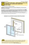
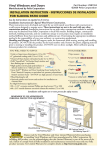
INSTALLATION INSTRUCTION -
NAIL FIN INSTALLATION BEFORE WEATHER BARRIER AND
FRAME SCREW OR CLIP INSTALLATION FOR REPLACEMENT
ALUMINUM-CLAD EXTERIOR HINGED PATIO DOORS (PELLA® PROLINE AND DESIGNER SERIES®)
ALUMINUM-CLAD EXTERIOR ENTRY DOORS (PELLA® AND ARCHITECT SERIES®)
Please read thoroughly and understand completely all the steps in this instruction prior to
beginning installation.
Installation with Nail Fin follow steps 1, 2, 3, 4, 6, 7
Replacement Installation Without Nail Fin follow steps 1, 2, 3, 5, 6, 7
Instrucciones en español en el reverso.
These instructions were developed and tested for use with typical wood frame wall construction
in a wall system designed to manage water. These instructions are not to be used with any other
construction method. Installation instructions for use with other construction methods or multiple
units may be obtained from Pella Corporation, a local Pella retailer or by visiting http://www.pella.
com. Building designs, construction methods, building materials, and site conditions unique to
your project may require an installation method different from these instructions and additional
care. Determining the appropriate installation method is the responsibility of you, your architect
or construction professional. Check with the individual (building owner, architect, contractor,
installer and/or consumer) responsible for the project in addition to local building code officials to
determine if these products comply with local codes.
REMEMBER TO USE APPROPRIATE PERSONAL PROTECTIVE EQUIPMENT.
9" w
Fin
Corner
ide F
lashin
Side
Flashing
Tape
Nailing Fin
g Pa
9"
F
l
a
s
h
i
n
g
per
Top
Flashing
Tape
9"
F
l
a
s
h
i
n
g
P
a
p
e
r
Astragal
9" Fla
shing
Side
Flashing
Tape
Pape
r
P
a
p
e
r
Sill Support
Sill Flashing Tape #1
Sill Flashing Tape #2
Note: This instruction is intended for walls with or without sheathing. Illustrations show wall
without sheathing.
Always read the Pella® Limited Warranty before purchasing or installing Pella
products. By installing this product, you are acknowledging that this Limited
Warranty is part of the terms of the sale. Failure to comply with all Pella installation
and maintenance instructions may void your Pella product warranty. See Limited Warranty for
complete details at http://warranty.pella.com.
The performance of any building is dependent upon the design, installation, and workmanship
RIWKHHQWLUHEXLOGLQJV\VWHP3HOOD&RUSRUDWLRQVWURQJO\UHFRPPHQGVFRQVXOWLQJDQH[SHULHQFHG
architect, contractor or structural engineer prior to installation of Pella products.
The individual (building owner, architect, contractor, installer and/or consumer) responsible for the
project must take into account local conditions, building codes, inherent component limitations,
the effects of aging and weathering on building components, and other design issues relevant to
each project.
The determination of the suitability of all building components for each project, as well as the
design and installation of flashing and sealing systems, are the responsibility of the building owner,
architect, contractor, installer and/or consumer.
YOU WILL NEED TO SUPPLY:
TOOLS REQUIRED:
Ř&RPSRVLWHRU,PSHUYLRXVVKLPVVSDFHUVWR
ŘJDOYDQL]HGURRILQJQDLOVOE
Ř[FRUURVLRQUHVLVWDQWZRRGVFUHZV
(Performance Upgrade & HurricaneShield)
Ř0DVRQU\VFUHZVIRUFRQFUHWHDSSOLFDWLRQV
0LQLPXPRIőGLDPHWHU[
Ř&ORVHGFHOOIRDPEDFNHUURGVHDODQWEDFNHU
WRIW
Ř3HOOD® SmartFlash™ foil backed butyl window and
door flashing tape or equivalent
Ř+LJKTXDOLW\H[WHULRUJUDGHSRO\XUHWKDQHRUVLOLFRQH
VHDODQWWRWXEHVSHUGRRU
Ř*UHDW6WXII™ Window and Door Insulating Foam
Sealant by the Dow Chemical Company or equivalent low pressure polyurethane window and door
IRDP'2127XVHKLJKSUHVVXUHRUODWH[IRDPV
Ř6LOOSDQRSWLRQDO
Ř3HOODDOXPLQXPVLOOVXSSRUWRUZRRGEORFNLQJ
Ř,QWHULRUWULPDQGRUMDPEH[WHQVLRQVWRIW
Ř7DSHPHDVXUH
4&"-"/5
4&"-"/5
Installation Clip Option:
ŘRULQVWDOODWLRQFOLSV
Ř[FRUURVLRQUHVLVWDQWIODWKHDGZRRGVFUHZV
Ř[FRUURVLRQUHVLVWDQWVFUHZVRU[
PDVRQU\VFUHZV
1
Ř/HYHO
Ř6TXDUH
Ř+DPPHU
Ř6WDSOHU
Ř6HDODQW*XQ
Ř6FLVVRUVRUXWLOLW\NQLIH
Ř7LQ6QLSV
Ř6FUHZGULYHUV
3KLOOLSVZLWKVKDIW
and small flat blade)
Ř77RU[:UHQFK
(Architect Series®)
Ř$OOHQZUHQFK
(Designer Series®)
Ř'ULOO
Ř'ULOO%LWVDQG
DQGPDVRQU\ELWIRU
concrete applications
ROUGH OPENING PREPARATION:
A. Confirm the opening is plumb and level.
Note: It is critical the bottom is level.
*OUFSJPS
"
1
ROUGH OPENING PREPARATION (continued):
B. Confirm the door will fit the opening.0HDVXUHDOO
IRXUVLGHVRIWKHRSHQLQJWRPDNHVXUHLWLVODUJHU
WKDQWKHGRRULQZLGWKDQGODUJHULQKHLJKW
0HDVXUHWKHZLGWKDWWKHWRSERWWRPDQGFHQWHU
0HDVXUHWKHKHLJKWDWWKHIDUOHIWVLGHWKHIDUULJKW
side, and in the center.
Note: 1-1/2" or more of solid wood blocking is
required around the perimeter of the opening.
Fix any problems with the rough opening before
proceeding.
Interior
1B
For Replacement Installation where nail fin is NOT
being used, go to Step 5.
C. Apply flashing paper at the bottom&&XWRQH
SLHFHRIŶDVKLQJSDSHUORQJHUWKDQWKHZLGWKRIWKH
rough opening. Position the top edge of the flashing
paper with the top of the sill plate. Center the flashing
paper with the opening width. Staple the flashing paper
to the sill plate.
Note: Sill flashing paper is not required for installation
on concrete floors.
Exterio
r
1D
1D
1C
1C
D. Apply flashing paper to the sides of the rough
opening'&XWWZRSLHFHVRIŶDVKLQJSDSHU
longer than the height of the rough opening. Apply
one piece to each jamb. Position the edge of the
flashing paper with the inside edge of the trimmer (jack
stud), and center the flashing paper with the height of
the rough opening. Staple the flashing paper to the
trimmer.
FOR DOORS USING OPTIONAL SILL PAN GO TO STEP 1I.
E. Apply sill flashing tape #1.&XWDSLHFHRIŶDVKLQJWDSHORQJHU
than the opening width. Apply at the bottom of the opening as
VKRZQ,(VRLWRYHUKDQJVWRWKHH[WHULRU
Note: The tape is cut 12" longer than the width so that it will
extend 6" up each side of the opening.
£
F. Tab the sill flashing tape and fold.&XWZLGHWDEVDWHDFKFRUQHU
IURPHDFKVLGHRIWKHFRUQHU))ROGWDSHWRWKHH[WHULRU
and press firmly to adhere it to the water resistive barrier.
* Apply sill flashing tape #2.&XWDSLHFHRIŶDVKLQJWDSHORQJHU
WKDQWKHRSHQLQJZLGWK$SSO\DWWKHERWWRPRYHUODSSLQJWDSH
E\DWOHDVW'2127DOORZWKHWDSHWRH[WHQGSDVWWKHLQWHULRU
IDFHRIWKHIUDPLQJ*
In-swing doors:
,IWKHZDOOGHSWKLVJUHDWHUWKDQDGGDWKLUGSLHFHRIŶDVKLQJ
WDSH7KHŶDVKLQJWDSHVKRXOGFRPHWRZLWKLQRIWKHLQWHULRU
face of the framing.
Note: The flashing tape may not fully cover the framing members.
£
£
£
H. Attach the aluminum sill support or wood blocking to the
H[WHULRURIWKHER[SODWHWRVXSSRUWWKHHGJHRIWKHGRRUVLOO
Place the sill support flush with the subfloor.
GO TO STEP 2
1
ROUGH OPENING PREPARATION (continued):
Optional Sill Pan Instructions:
I. Cut the sill panWRWKHZLGWKRIWKHURXJKRSHQLQJSOXV
Note: The 2" added onto the rough opening width is for a 1" bend on each end.
J. Make a 1" cut in each fold at both end of the sill pan.
Note: These cuts will allow the edges of the sill pan to be bent.
Note: 4-5/8" wide for Out-Swing and In-Swing for 4-9/16" wall condition. For other wall
conditions, measure wall depth and add 1/16".
1"
1J
INTERIOR SIL
1"
L PAN LIP
Variable
EXTERIOR SIL
L PAN LIP
K. Cut 1" off each end of the
interior sill pan lip.
1"
1"
1K
INTERIOR SILL
EXTERIOR SILL
L. Bend each end of the sill pan
upwards.
1L
INTERIOR SILL
EXTERIOR SILL
0 Install the sill pan by sliding into
placeXQWLOWKHH[WHULRUVLOOSDQOLSLV
ŶXVKZLWKWKHH[WHULRURIWKHURXJK
opening.
N. Apply sill flashing tape. Cut a
SLHFHRIŶDVKLQJWDSHORQJHU
than the opening width. Apply
at the bottom of the opening,
FRYHULQJWKHH[WHULRUVLOOSDQOLSDV
shown.
Note: If applicable, apply spray
adhesive to building felt prior to
applying the flashing tape.
PAN LIP
PAN LIP
PAN LIP
PAN LIP
1M
Exterior
EXTERI
OR SILL
PAN LI
Install
P
agains flush
rough t exterior
openin
g.
1N
EXTERI
OR SILL
PAN LI
P
Flashing
Tape
Weath
er Barr
ier
3"
O. Cut two 9" pieces of flashing tape with a
[WDEDWWKHERWWRPRQRSSRVLWH
corners as shown.
3"
1O
9"
9"
1-1/2"
1-1/2"
3"
1-1/2"
Tabs
P. Apply the tabbed 9" pieces of flashing
tap.7KHWDSHLVDSSOLHGVRZLOO
cover the inside of the rough opening
and lap over the side flange of the sill
SDQ7KH[WDEODSVRYHUWKH
bottom flashing tape as shown.
1-1/2"
Tabs
1-1/2"
1P
Q. Cut two 6" pieces of flashing tape
and apply to each side of the rough
opening, overlapping the first piece
E\DQGODSSLQJWKHERWWRPRYHUWKH
side flange of the sill pan as shown.
1-1/2"
9"
Side
Flange
1"
1Q
9"
EXTERI
EXTERI
OR SILL
PAN LI
P
Flashing
Tape
1-1/2"
9"
OR SILL
PAN LI
P
Flashing
Tape
1-1/2"
1
ROUGH OPENING PREPARATION (continued):
R. Cut a piece of flashing tape to the width of the opening. Install to the flanges of the sill
SDQDQGRYHUODSWKHWDSHIURPVWHS1E\,IQHHGHGDGGDVHFRQGRUWKLUGSLHFHRI
flashing tape until the sill pan is covered to the interior sill pan lip.
Note: The purpose of this tape is to seal the sill screws when installing the door.
S. Cut two pieces of flashing tape 1-1/2" x 6"
and apply to the bottom corners of the opening
by beginning in the corner of the sill pan, with
RIWKHWDSHDSSOLHGWRWKHVLOOSDQDQG
RIWKHWDSHDSSOLHGWRWKHVLGHŶDQJH7KH
UHPDLQGHURIWKHWDSHLVWREHDWDGHJUHH
DQJOHRQWRWKHH[WHULRU
1S
1R
INTERIO
R SILL PA
EXTERI
OR SILL
N LIP
PAN LI
P
1"
T. Attach the aluminum sill support or wood
blockingWRWKHH[WHULRURIWKHER[SODWHWR
support the edge of the door sill. Place the sill
support flush with the subfloor.
1P
1T
INTERIO
R SILL PA
EXTERI
OR SILL
2
N LIP
PAN LI
P
PREPARE THE DOOR FOR INSTALLATION:
TWO OR MORE PEOPLE WILL BE REQUIRED TO HANDLE THE PANEL AND FRAME
SAFELY.
A. Remove plastic wrap and cardboard packaging from door. Do not remove plastic
shipping spacers. The shipping spacers will help keep the door square during installation.
Do not open the door until it is fully fastened.
Note: If grilles or hardware are removed from the door at this time, label them and store
them in a protected area.
B. For doors without EnduraClad®
Brickmould: Fold out installation
ŵQWRr%HFDUHIXOQRWWR
remove or tear the fin corners.
Note: If the fin corner is not
at 90°, the door will not align
correctly on the interior.
Ó
Door with
Brickmould
Note: The nail fin on doors with
brickmould and nail fin will
come from the factory folded up.
C. Doors using Installation Clips: Install
installation clips. Place each clip so
the lip is facing up and against the
installation fin at the locations shown in
the placement diagram. Secure each clip
E\GULYLQJD[FRUURVLRQUHVLVWDQW
screw through each of the outer two
holes of the three holes shown.
Note: If clips are to be bent; pre-bend
before attaching to frame.
Note: Bending clips after attaching to
frame will bow the frame.
#6 x 5/8” corrosion
resistant screws
6“ from end
Lip
2C
3
SETTING AND FASTENING THE DOOR:
A. Place three 3/8" beads of sealant.3ODFHWKHŵUVWEHDGVVHDODQWLQIURQWRIWKHEDVH
of the interior sill pan lip. This bead should also continue up the corner of the sill pan
DWHDFKHQGVHDOLQJWKHYHUWLFDOMRLQWVRIWKHVLOOSDQOHJV&RQWLQXHWKHŵUVWEHDGXS
RQWRHDFKMDPEVLGHRIWKHURXJKRSHQLQJ7KHVHFRQGEHDGVKRXOGEHDSSUR[LPDWHO\
IURPWKHH[WHULRUHGJHRIWKHURXJKRSHQLQJUXQQLQJIURPMDPEWRMDPEZLWKD
break in the middle of the opening. Place a third sealant bead in the groove of the sill
VXSSRUWIURPHQGWRHQGRU~IURPWKHH[WHULRUHGJHRIWKHZRRGEORFNLQJ
1/2"
1st Bead
2nd Bead
6"
3A
Leave a 2" br
in center of eak
INTERIO
pan
R SILL PA
N LIP
6”
2
3A
1
3
EXTERIO
R SILL P
AN LIP
3rd Bead
Applications without sill pan
TWO OR MORE PEOPLE WILL BE REQUIRED FOR THE FOLLOWING STEPS:
Designer Series Doors:
B. Cut and remove the strap that runs from the door lock to the sill of the door.
For doors with no lock/bore:
C. Remove the screws and blocking from the head and sill.
Caution: The door panels will swing freely.
D. Insert the door from the exterior of the building.
DO NOT slide the bottom of the door into the
opening. Sliding will damage the sealant lines.
Place the bottom of the door at the bottom
of the opening, then tilt the top into position.
Center the door between the sides of the
opening to allow clearance for shimming, and
insert one roofing nail in the first hole from
the corner on each end of the top nailing fin.
These are used to hold the door in place while
shimming it plumb and square.
E. Plumb and square door. Place shims at each
hinge and lock strike location between the
door and the sides of the opening. Keep shims
EDFNIURPWKHLQWHULRUIDFHRIWKHGRRU
frame. Insert shims in other locations as needed
VWDUWLQJXSIURPWKHERWWRPRIWKHGRRUWR
square it in the opening. Check for frame twist;
confirm consistent weatherstrip compression
DURXQGWKHSHULPHWHURIWKHGRRU0DNHVXUH
the panels are even across the bottom.
Note: On center latch double doors the lock
strike will not be shimmed since it is located in
the center of the unit. DO NOT over shim.
3D
3E
3
SETTING AND FASTENING THE DOOR (continued):
F. Check the interior reveal. 0DNHVXUH
the measurement from the interior face
of the door to the interior face of the
wall is equal at several points around
the door.
Note: If dimensions are not equal,
check to make sure the fins are folded
out to 90° at all points.
Clip or Frame Screw Installation,
go to Step 5I
Interior
3E
3F
3E
3F
3D
3E
3E
3D
1 INCHES
20 3
0 40 2
3
50 6
0 70
mm
3D
3E
* Fasten the door WRRSHQLQJE\GULYLQJJDOYDQL]HGURRŵQJQDLOLQWRHDFKSUH
punched hole in the nailing fin.
Note: Make sure the fin corner is lying as flat as possible
3G
H. Carefully open the door(s) and
remove all shipping spacers.
Note: Be sure to remove the
spacers from the bottom edge
of the door panel.
Double Doors with Multipoint latch in center: Use the construction handle to operate
the active door handle. Operate the flushbolts per the instructions on the label on
the strike located on the astragal.
I.
Designer Series® Out-Swing: Install sill screws. Place a dab of sealant in each
RIWKHSUHGULOOHGKROHVLQWKHERWWRPRIWKHXQLWVLOO7KHQLQVHUWD[
FRUURVLRQUHVLVWDQWVFUHZSURYLGHGLQWRHDFKKROH)RUPDVRQU\ŶRRUVXVD
PDVRQU\VFUHZLQSODFHRIWKHSURYLGHGVFUHZSLORWGULOOSHUVFUHZPDQXIDFWXUHUőV
recommendations.
All other: Sill screws are not needed.
For combinations (Multi-wide): 3UHGULOOIUDPHDWPXOOLRQHQGVIURPHDFK
PXOOLRQMRLQWDQGLQVHUW[FRUURVLRQUHVLVWDQWVFUHZV)RUPDVRQU\DSSOLFDWLRQV
XVHPDVRQU\VFUHZV
J. For Low Profile Sills: 7KURXJKHDFKLQVWDOODWLRQVFUHZKROHGULOODSLORWDQGLQVWDOO
D[FRUURVLRQUHVLVWDQWVFUHZSURYLGHGLQWRWKHSLORWKROHLQWRWKHŶRRU)RU
doors including a standard lock install tubs per instruction included with the sill strike
package.
Note: For concrete floors use masonry screws a minimum size of 3/16" diameter x 3"
and pilot per manufacturer’s recommendations for the screw.
3
SETTING AND FASTENING THE DOOR (continued):
K. Double Doors Only:
Designer Series®: Place a dab of sealant into the center sill
Interio
VWULNHKROHDQGLQVWDOOWKH[ŶDWKHDGFRUURVLRQUHVLVWDQW
r
VFUHZVSURYLGHGRUDPDVRQU\VFUHZVLQWRWKHKROH
3K
3L
ProLine®: Remove the screw from the sill strike located on
the door sill, then place a dab of sealant into the sill strike
KROHDQGLQVWDOOWKH[ŶDWKHDGFRUURVLRQUHVLVWDQWVFUHZ
SURYLGHGRUDPDVRQU\VFUHZLQWRWKHKROH
3J
Entry Doors: Remove the two screws from the sill strike
3K
located on the door sill. Place a dab of sealant into the
FHQWHUVLOOVWULNHKROHDQGLQVWDOOWKH[ŶDWKHDG
FRUURVLRQUHVLVWDQWVFUHZVSURYLGHGRUDPDVRQU\
screws into the hole.
L. Double Doors Only: Shim between the frame and the rough opening at the head strike
ORFDWLRQDQGDWHYHU\IUDPHDQFKRUKROHORFDWLRQ.HHSVKLPVEDFNIURPLQWHULRUIDFHRI
the door frame.
Designer Series:,QVWDOOWKH[ŶDWKHDGFRUURVLRQUHVLVWDQWVFUHZVSURYLGHGLQWRWKH
hole.
ProLine:5HPRYHWKHVFUHZIURPWKHKHDGVWULNHORFDWHGRQWKHGRRUKHDGWKHQLQVWDOOWKH
[ŶDWKHDGFRUURVLRQUHVLVWDQWVFUHZVSURYLGHGLQWRWKHKROH
Entry Doors: Remove the two screws from the head strike located on the door head. Install
WKH[ŶDWKHDGFRUURVLRQUHVLVWDQWVFUHZVSURYLGHGLQWRWKHKROH
Note: For doors with pre-drilled installation holes in the head. If installation holes are
present, drill 1/8" diameter pilot hole into the rough opening and install a #8 x 3" corrosion
resistant screw (provided) in each hole.
0 2QHDFKKLQJHVWDUWLQJDWWKHWRSLQVHUWDFRUURVLRQUHVLVWDQW
VFUHZ[SURYLGHGLQWRWKHRSHQVFUHZKROH0DNHVXUH
the screw passes through the shims and into the structural
framing.
N. Check door operation. Open and close the door to check for
SURSHURSHUDWLRQ0DNHVXUHWKHGRRUZLOOODWFKFRUUHFWO\
Note: If there are any problems with the operation, check to
confirm the door frame is installed plumb, level and square.
If the reveal between the door panel(s) and frame is not
even, adjustments may be made:
Interior
3L
3M
Doors without adjustable hinges: Plastic shims located
behind the hinges may be removed to adjust the reveal
between the door panel and door frame. Additional hinge
shims may be added if required.
Note: Doors with adjustable hinges will have a (+)(-) on the
door panel hinge leaf to indicate possible adjustments and
doors without adjustable hinges do not have adjustment
indicators.
Adjustable hinges are not designed to make up for incorrect
installation of a door frame. Before adjusting hinges, confirm
the door is installed plumb, level and square.
Adjustable
Hinge
Non-Adjustable
Hinge
O. For Doors with adjustable hinges: The hinges can be used to move the panel side to side
by moving all hinges in the same direction or the hinges can slightly rotate the panel by
DGMXVWLQJWKHKLQJHVLQRSSRVLWHGLUHFWLRQV8VHD77RU[ZUHQFKIRU(QWU\'RRUVRUD
Allen wrench for Designer Series doors to turn the center screw clockwise (+) to increase the
space between the hinge side of the frame and door panel. Turn the center screws counterclockwise (-) to decrease the space between the hinge side of the frame and the door panel
.
Note: Do not adjust the hinge with the top and bottom screws loose; this could force the
hinge to adjust beyond its design capability which can cause the hinge to bind, damage
the hinge and/or pull out the screws. A 3/4 turn of the center screw provides approximately
5/32" adjustment.
3
SETTING AND FASTENING THE DOOR (continued):
P. Doors with a lock strike in the side (jamb) and without a sidelight on the lock side:
'ULOODQGLDPHWHU[GHHSSLORWKROHLQWRWKHURXJKRSHQLQJWKURXJKWKHSUHGULOOHG
holes located in the frame as follows:
3Door Frame Corner:
Drill pilot holes through the pre-drilled hole located in the upper frame corner on the lock
MDPEVLGHDSSUR[LPDWHO\IURPWKHWRSRIWKHGRRUIUDPHKHDG
3Doors with Multi-point Lock:
Drill through the one pre-drilled hole located in each lock strike. (Pull back frame
weatherstrip to locate open hole in strike).
3Center Latch and Deadbolt Lock:
'ULOOWKURXJKWKHPRXQWLQJKROHORFDWLRQV,QVHUWD[VFUHZLQWRWKHSLORWKROHV
making sure it passes through the shim and into the rough opening.
Note: This step does not apply to center latching double doors.
3P1
3O
Head
3O
3P3
3P
3P2
3P
3P2
3P
~ 8”
J
a
m
b
Pull back weatherstrip to expose strike hole.
4
INTEGRATING THE DOOR TO THE
WATER RESISTIVE BARRIER:
Flashing
Tape
Note: The flashing tape must be applied
approximately 1/2" onto the frame cladding at the
jambs and head. Pre-folding the tape at 1/2" before
removing the paper backing will make it easier to
apply the tape correctly. If the siding is less than 1/2"
thick, adjust the dimension of the fold so the exterior
sealant line will cover the exterior edge of the tape.
A. Apply side flashing tape. Cut two pieces of flashing
WDSHORQJHUWKDQWKHIUDPHKHLJKWRIWKHGRRU
$SSO\RQHSLHFHRQWRWKHIUDPHFODGGLQJRYHU
the nailing fin and onto the water resistive barrier on
HDFKVLGH7KHWDSHVKRXOGH[WHQGDERYHWKHWRS
RIWKHGRRUDQGEHORZWKHERWWRPRIWKHGRRU
Press the tape down firmly while folding down the
H[FHVVWDSHDWWKHWRSDQGERWWRPRIWKHGRRU
&YUFSJP
S
Î
4A
4
INTEGRATING THE DOOR TO THE
WATER RESISTIVE BARRIER (continued):
B. Apply top flashing tape. Cut a piece of flashing
tape long enough to go across the top of the door
DQGH[WHQGDWOHDVWSDVWWKHVLGHŶDVKLQJWDSH
RQERWKVLGHV$SSO\WKHWDSHRQWRWKHIUDPH
cladding, over the top nailing fin as shown. Fold
the overlapping tape down, and press all tape
down firmly.
&YUFSJP
S
Î
4B
Note: The top flashing tape must overlap the side
flashing tape to prevent water from getting behind it.
C. Apply the top flashing paper. Cut one piece of
ŶDVKLQJSDSHUDWOHDVWORQJHUWKDQWKHZLGWKRI
the rough opening. Position the bottom edge of the
flashing paper flush with the frame of the door and
center the flashing paper with the door. Staple the
flashing paper to the header.
Note: When applying the first layer of building felt,
ensure the sill flashing paper overlaps the building
felt. This will tie the door system into the building
water management system.
Î
4C
As required by local code (such as Florida product approval system), additional anchors
may be required. Install them at this time.
5
DOOR REPLACEMENT IN SIDING
WITHOUT NAIL FIN:
Head Flashing Instruction and Rough Opening Preparation
Note: Pella Recommends and some codes require the use of a head drip flashing. If there
is a functioning, existing flashing, proceed to step 5D.
A. Prepare the head flashing by cutting it the same width
as the j-channel/siding opening.
HOUSE WRAP
B. Pry the top (head) j-channel/siding away from the
sheathing enough so the head flashing can be slid
under the house wrap.
SIDING
J-CHANNEL
FLASHING TAPE
C. Insert the head flashing behind the j-channel/
siding and behind the house wrap (if present).
HEAD FLASHING
5
DOOR REPLACEMENT IN SIDING
WITHOUT NAIL FIN (continued):
D. Clean the vinyl j-channel/trim and rough opening with isopropyl alcohol or
window cleaner to make sure it is free of dirt and debris before proceeding.
E. Place a 3/8" bead of sealant (or enough to cover
the area) between the j-channel and the rough
opening at the head and jambs only. Tool the
sealant with a putty knife to press the sealant into
the opening.
CAUTION: The cut fin may have sharp edges!
HEAD
AND
JAMBS
ONLY
2B
5E
PRESS
SEALANT
INTO
OPENING
F. Place a 3/8" bead of sealant at each corner of
the opening.
2C
5F
* Starting at the top (head) of the opening, cut
RQHSLHFHRIŶDVKLQJWDSHORQJHUWKDQWKH
width of the rough opening. Place the flashing
tape onto the j-channel edge, over the sealant
DQGRQWRWKHURXJKRSHQLQJVXUIDFHDQGH[WHQG
GRZQWKHMDPEV
5G
%
For Sill Preparation see steps 1E - 1T.
H. Cut two pieces of flashing
tape 6" longer than the height
of the opening. On one side
(jamb) of the opening, start the
tape in the upper corner and
work down and onto the sill.
0DNHVXUHWKHWDSHLVDSSOLHG
from the j-channel edge over
the sealant and onto the rough
opening surface.
'-"4)*/(5"1&
1-"$&.&/5(6*%&
)&"%5"1&
5H
+".#5"1&4
4*--5"1&4
See steps 3A - 3F only for Setting the Door.
5
DOOR REPLACEMENT IN SIDING
WITHOUT NAIL FIN (continued):
Fastening Door to Opening
I. After setting the door plumb level & square, secure the door to the opening. If using
frame screw method then have two people hold the door upright and secure while a
WKLUGSHUVRQRSHQVRQHSDQHODQGLQVHUWVDVFUHZWKURXJKWKHMDPEGRZQIURPWKHWRS
corner, then open the other panel and repeat on the opposite jamb. See below for pilot
KROHVFUHZVL]HORFDWLRQGHWDLOV
ALTERNATE ANCHORING METHODS, CLIP AND SCREW PLACEMENT:
DOUBLE OPERABLE
SINGLE FIXED OR OPERABLE
3P
5I
3P
5I
6"
6"
16" MAX
O.C.
6"
16" MAX
O.C.
6"
6"
6"
6"
3P
5I
3P
5I
16"
MAX.
O.C.
16"
MAX.
O.C.
6"
6"
6"
16" MAX
O.C.
6"
6"
16" MAX
O.C.
16" MAX
O.C.
3"
6"
6"
6"
6"
16" MAX
O.C.
3"
6" 6"
6"
3P
5I
16"
MAX.
O.C.
16"
MAX.
O.C.
6"
6"
6"
6"
16" MAX
O.C.
6"
16"
MAX.
O.C.
16"
MAX.
O.C.
6"
6"
6"
16" MAX
O.C.
3P
5I
6" 6"
3"
Vent Placement
Fixed Placement
3"
Vent Placement
Fixed Placement
Fixed and Vent
Placement
Fixed Placement
Vent Placement
Out-Swing Screw Locations
6"
6"
In-Swing Screw Locations
6"
5
DOOR REPLACEMENT IN SIDING
WITHOUT NAIL FIN (continued):
Frame Screw Method:
Note: If installing with installation clips, proceed to step P.
J. Jambs'ULOODQGFRXQWHUVLQNGLDPHWHUFOHDUDQFHKROHVWKURXJKWKHGRRUIUDPHRQO\
and not into the rough opening at the locations shown on the diagrams.
Note: Out-Swing Doors Only - If choosing to locate clearance
holes through the frame to be concealed by door panel; remove
frame weatherstrip and drill holes under the weatherstrip.
5J
K. Frame Head'ULOODQGFRXQWHUVLQNGLDPHWHUFOHDUDQFHKROHVWKURXJKWKHGRRU
frame head only and not into the rough opening at the locations shown on the diagrams.
L. Threshold'ULOODQGFRXQWHUVLQNGLDPHWHUFOHDUDQFHKROHVWKURXJKWKHWKUHVKROG
but not into the rough opening at the locations shown on the diagrams
0 Drill 1/8" x 1" deep pilot holes through the clearance holes and into the rough opening
framing in the head, jambs and threshold of the unit frame.
N. Secure the jambs and head of the door.'ULYH[FRUURVLRQUHVLVWDQWZRRG
screws through the door frame and shim, into the rough framing. Drive the screws until
snug but DO NOT over-tighten the screws. DO NOT bend or bow the unit frame.
O. Secure the sillE\GULYLQJ[FRUURVLRQUHVLVWDQWZRRGVFUHZWKURXJKWKH
WKUHVKROGLQWRWKHŶRRU)RUPDVRQU\DSSOLFDWLRQVXVHPDVRQU\VFUHZVDPLQLPXPRI
GLDPHWHU[DQGSLORWGULOOSHUVFUHZPDQXIDFWXUHUőVUHFRPPHQGDWLRQV
Go back to 3H - 3P to complete fastening through hinges and strikes.
Installation Clip Method:
See Step 2C for Clip Application Details
P. Fasten the door to the opening by driving
WZR[FRUURVLRQUHVLVWDQWVFUHZV
into the pre-punched holes in the clips.
If the clips are bent and fastened to the
interior stud/block, install the screws as
close to the bend as possible.
Note: DO NOT shim above the door. For
masonry openings use two masonry screws
that are a minimum size of 3/16" x 1-1/2"
per clip. Pre-drill the masonry per screw
manufacturer’s recommendations before
attempting to drive the screws in.
5F
5P
Go back to 3H - 3P to complete fastening through hinges and strikes.
6
INTERIOR SEAL:
Caution: Ensure use of low pressure polyurethane window and door insulating foams
and strictly follow the foam manufacturer’s recommendations for application. Use of
high pressure foams or improper application of the foam may cause the door frame to
bow and hinder operation.
A. Add a sealant bead across the inner sill and 6" up
each jamb between the frame and rough opening.
B. Apply insulating foam sealant. From the interior,
LQVHUWWKHQR]]OHRIWKHDSSOLFDWRULQWRWKHVSDFH
between the door and the rough opening
DSSUR[LPDWHO\SDVWWKHHGJHRIWKHIUDPH
DQGSDVWWKHMDPEH[WHQVLRQVDQGDSSO\D
GHHSEHDGRIIRDP7KLVZLOODOORZURRP
IRUH[SDQVLRQRIWKHIRDPDQGZLOOPLQLPL]H
VTXHH]HRXW$SSO\VHDODQWDFURVVWKHLQWHULRU
surface of the shims to create a continuous seal.
Follow foam manufacturer's instructions.
Note: DO NOT place any foam between jamb
extensions and the rough opening.
C. Check the door operation by opening and
closing the door.
Note: If the door does not operate correctly,
check to make sure it is still plumb, level, square
and that the sides are not bowed. If adjustments
are required, remove the foam with a serrated
knife. Adjust the shims, and reapply the insulating
foam sealant.
Interior
6A
6B
6C
6A
6"
7
SEALING THE DOOR TO THE
EXTERIOR WALL CLADDING:
When applying siding, brick veneer or other exterior finish material, leave adequate space
between the door frame and the material for sealant. Refer to the illustration corresponding to
your finish material.
Note: The sealant details shown are standard recommendations from the sealant industry.
Contact your sealant supplier for recommendations and instructions for these and any other
applications.
BRICK
VENEER
VINYL/STEEL
SIDING
Backer Rod
and Sealant
typical
3/8"
Clearance
Accessory
Groove
Insulating
Foam
3/8"
3/8"
Clearance
Accessory
Groove
Insulating
Foam
Perimeter Sealant
must extend to
room side of
Accessory Groove.
Insulating
Foam
Perimeter Sealant
must extend to
room side of
Accessory Groove.
3/8"
3/8"
Min.
STUCCO
Backer Rod and
Sealant typical
3/8" Clearance
Accessory
Groove
Perimeter Sealant
must extend to
roomside of
Accessory Groove.
Insulating
Foam
Perimeter Sealant
must extend to
room side of
Accessory Groove.
3/8"
3/8"
Clearance
Accessory
Groove
3/8"
Min.
Backer Rod
and Sealant
typical
3/8"
Clearance
Accessory
Groove
Backer Rod
and Sealant
typical
Insulating
Foam
Perimeter Sealant
must extend to
room side of
Accessory Groove.
3/8"
3/8"
Min.
WOOD
SIDING
WITH
TRIM
SOUTHWESTERN
WALL
WITH
STUCCO
Backer Rod
and Sealant
typical
3/8"
3/8"
Min.
3/8"
Min.
Replacement Frame:
Note: When applying siding, brick veneer or other exterior finish materials, leave adequate
space between the door frame and the material for sealant. Refer to the illustration
corresponding to your finish material. Not allowing adequate space or not using backer rod
may cause the sealant to break down prematurely and allow water to infiltrate.
BRICK VENEER
Backer rod
and
sealant typical
Insulating
Foam
WOOD SIDING
WITH TRIM
Backer rod
and
sealant typical
Insulating
Foam
3/8"
3/8"
Min.
3/8"
7
SEALING THE DOOR TO THE
EXTERIOR WALL CLADDING (continued)
A. Insert backer rod into the space around the
GRRUVRWKHUHLVDSSUR[LPDWHO\WR
clearance between the backer rod and the
H[WHULRUIDFHRIWKHGRRU
Note: Backer rod adds shape and depth for
the sealant line.
B. Apply a bead of high quality exterior grade
sealant to the entire perimeter of the door.
C. Shape, tool and clean excess sealant. When
finished, the sealant should be the shape of
an hourglass.
D. Remove plastic guards at the base of the
door once construction is complete.
E. Install the hardware. Refer to the instructions
LQFOXGHGLQWKHKDUGZDUHER[
7A
7B
INTERIOR FINISHING
If products cannot be finished immediately, cover with clear plastic to protect from dirt, damage
and moisture. Remove any construction residue before finishing. Sand all wood surfaces lightly
ZLWKJULWRUŵQHUVDQGSDSHU'2127XVHVWHHOZRRO%(&$5()8/127726&5$7&+7+(
*/$665HPRYHVDQGLQJGXVW
Pella products must be finished per the below instructions; failure to follow these instructions voids
the Limited Warranty.
FINISHING INSTRUCTIONS
Paint or finish immediately after installation.
Note: DO NOT paint, stain or finish weatherstrip or vinyl parts! If paint, stain or finish gets on the
weatherstripping, wipe it off immediately with a damp cloth. To maintain proper performance, do
not remove weatherstrip, foam corner seal wedges or gaskets. Air and water leakage may result
if these factory-installed items are removed. After finishing, allow doors to dry completely before
closing them. Pella will not be responsible for finishing imperfections. The use of unapproved
finishes, solvents or cleaning chemicals may cause adverse reactions with door materials. Pella will
not be responsible for problems caused by the use fo unapproved materials. If in doubt, contact
your local retailer or representative.
Use of inappropriate finishes, solvents, brickwash or cleaning chemicals will cause adverse actions
with window and door materials and voids the Limited Warranty.
&DUHDQGPDLQWHQDQFHLQIRUPDWLRQLVDYDLODEOHLQWKH3HOOD2ZQHU
V0DQXDO<RXFDQREWDLQDQ
owner's manual by contacting your local Pella retailer. This information is also available on www.
pella.com.
Factory Prefinished Panels: A door panel that has been prefinished with stain or paint from the
factory requires no additional finishing. Clean the surface with mild soap and water. DO NOT use
abrasives. DO NOT scrape or use tools that might damage the surface.
Clad Exterior Frame:7KHH[WHULRUIUDPHLVSURWHFWHGE\DOXPLQXPFODGGLQJZLWKRXUWRXJK
EnduraClad® baked-on-factory finish that needs no painting. Clean this surface with mild soap and
water. DO NOT use abrasives. DO NOT scrape or use tools that might damage the surface.
Panel Cleaning and Prep Instructions for Unfinished or Primed Panels: Dry wipe dust from
GRRUVJHQWO\([DPLQHGRRUIRUSRVVLEOHVPXGJHVRUŵQJHUSULQWVPDGHIURPQRUPDOKDQGOLQJRU
construction. To remove smudges, lightly wipe surface with warm water. DO NOT sand surface of
ŵEHUJODVVSDQHO6FXIIVDQGZLWKOLJKWJUDGHVDQGSDSHURUDEUDVLYHSDGJULWRUKLJKHU5LQVH
surface with mineral spirits for fiberglass panels and warm water for steel panels. Let door and
sidelight surfaces dry completely before applying finish. Finish the door panels as soon as possible
after installation.
Staining fiberglass panels or unfinished interior frame members: Fiberglass door and sidelight
panels may be stained with a gel stain if a wood look is desired. Pella offers stain kits in a variety
RIFRORUV$SSO\DQGŵQLVKSHUWKHVWDLQNLWPDQXIDFWXUHU
VLQVWUXFWLRQ(QVXUHWKDWDOOH[SRVHG
SDQHOHGJHVDUHŵQLVKHGWRPLQLPL]HWKHFKDQFHRIGDPDJH8QSULPHGLQWHULRUIUDPHSDUWV
may be stained with wood stains and should be finished with a minimum of two coats of a clear
SRO\XUHWKDQHŵQLVK'2127EULGJHWKHWRSFRDWEHWZHHQWKHRXWHUHGJHRIWKHJOD]LQJIUDPH
and the door panel.
Note: The fiberglass base color tone will vary. This variance is normal and will not impact the stain
color of the door.
Painting Instructions::RRGGRRUIUDPHH[WHULRUVSUHPLXPVWHHOGRRUSDQHOVDQGVLGHOLJKWVDUH
IDFWRU\SULPHG,IDSDLQWŵQLVKLVGHVLUHGŵQLVKWKHSDUWVZLWKWZRFRDWVRIDODWH[SDLQW
that has a good blocking resistance. On units with glass, do not bridge paint between the outer
HGJHVRIWKHJOD]LQJIUDPHDQGWKHGRRUSDQHO2QŵEHUJODVVSURGXFWVEUXVKWKHSDLQWLQWKH
VDPHGLUHFWLRQDVWKHVLPXODWHGZRRGJUDLQ(QVXUHWKDWDOOH[SRVHGSDQHOHGJHVDUHŵQLVKHGWR
PLQLPL]HWKHFKDQJHRISDQHOGDPDJH
Failure to use the correct type of finish may result in a door that sticks shut. Ask a qualified paint
professional to specify a product with good blocking resistance.
On patio doors:,WLVRSWLRQDOWRSDLQWVWDLQRUŵQLVKWKHYHUWLFDODQGKRUL]RQWDOSDQHOHGJHV
EXTERIOR FINISHING
7KHH[WHULRUIUDPHDQGVDVKDUHSURWHFWHGE\DOXPLQXPFODGGLQJZLWKD3HOOD(QGXUD&ODGpRU
EnduraClad Plus baked-on factory finish that needs no painting. Clean this surface with mild
soap and water. Stubborn stains and deposits may be removed with mineral spirits. DO NOT use
abrasives. DO NOT scrape or use tools that might damage the surface.
Use of inappropriate finishes, solvents, brickwash or cleaning chemicals will cause adverse
reactions with window and door materials and voids the Limited Warranty.
CARE AND MAINTENANCE
&DUHDQGPDLQWHQDQFHLQIRUPDWLRQLVDYDLODEOHLQWKH3HOOD2ZQHUőV0DQXDO<RXFDQREWDLQDQ
RZQHUőVPDQXDOE\FRQWDFWLQJ\RXUORFDO3HOODUHWDLOHU7KLVLQIRUPDWLRQLVDOVRDYDLODEOHDW
www.pella.com.
IMPORTANT NOTICE
Because all construction must anticipate some water infiltration, it is important that the wall system
be designed and constructed to properly manage moisture. Pella Corporation is not responsible
for claims or damages caused by anticipated and unanticipated water infiltration; deficiencies in
building design, construction and maintenance; failure to install Pella® products in accordance with
Pella installation instructions; or the use of Pella products in wall systems which do not allow for
proper management of moisture within the wall systems. The determination of the suitability of all
building components, including the use of Pella products, as well as the design and installation of
flashing and sealing systems are the responsibility of the Buyer or User, the architect, contractor,
installer, or other construction professional and are not the responsibility of Pella.
Pella products should not be used in barrier wall systems which do not allow for proper
PDQDJHPHQWRIPRLVWXUHZLWKLQWKHZDOOV\VWHPVVXFKDVEDUULHU([WHULRU,QVXODWLRQDQG)LQLVK
6\VWHPV(,)6DOVRNQRZQDVV\QWKHWLFVWXFFRRURWKHUQRQZDWHUPDQDJHGV\VWHPV([FHSWLQWKH
VWDWHVRI&DOLIRUQLD1HZ0H[LFR$UL]RQD1HYDGD8WDKDQG&RORUDGRPella makes no warranty
of any kind and assumes no responsibility for Pella windows and doors installed in barrier wall
systems. In the states listed above, the installation of Pella products in barrier wall or similar
systems must be in accordance with Pella installation instructions.
Product modifications that are not approved by Pella Corporation will void the Limited Warranty.
TROUBLESHOOTING - Adjustable Strike Latching Issues
Issue 2:
Door needs to close
more tightly against
the weather-strip.
Remove the strike
and adjustable
strike shim. Remove
the tabs from the
adjustable strike
shim and install
so that the thicker
side is visible at
the strike edge.
Reinstall the strike.
Issue 1:
Door is difficult
to latch. Remove
the strike and
adjustable
strike shim then
reinstall the
strike.
"EK4USJLF4IJN
FOEWJFX
'BDUPSZ
JOTUBMMFE
TJEF
4JEFUPCF
VTFEJO
*TTVF
5"#4
"EKVTUBCMFTUSJLFTIJN
TJEFWJFX
4USJLF
GSPOUWJFX