1
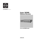
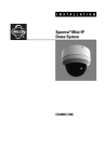
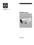
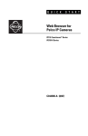
INSTALLATION/OPERATION
RCS Series
Rack Mount
Power Supply
C607M-E (2/09)
Contents
Regulatory Notices . . . . . . . . . . . . . . . . . . . . . . . . . . . . . . . . . . . . . . . . . . . . . . . . . . . . . . . . . . . . . . . . . . . . . . . . . . . . . . . . . . . . . . . . . . . . . . . . . . . . 5
Important Safety Instructions . . . . . . . . . . . . . . . . . . . . . . . . . . . . . . . . . . . . . . . . . . . . . . . . . . . . . . . . . . . . . . . . . . . . . . . . . . . . . . . . . . . . . . . . . . . . 6
Description. . . . . . . . . . . . . . . . . . . . . . . . . . . . . . . . . . . . . . . . . . . . . . . . . . . . . . . . . . . . . . . . . . . . . . . . . . . . . . . . . . . . . . . . . . . . . . . . . . . . . . . . . . . 7
Models . . . . . . . . . . . . . . . . . . . . . . . . . . . . . . . . . . . . . . . . . . . . . . . . . . . . . . . . . . . . . . . . . . . . . . . . . . . . . . . . . . . . . . . . . . . . . . . . . . . . . . . . . 7
Before You Begin . . . . . . . . . . . . . . . . . . . . . . . . . . . . . . . . . . . . . . . . . . . . . . . . . . . . . . . . . . . . . . . . . . . . . . . . . . . . . . . . . . . . . . . . . . . . . . . . . . . . . . 8
Parts List . . . . . . . . . . . . . . . . . . . . . . . . . . . . . . . . . . . . . . . . . . . . . . . . . . . . . . . . . . . . . . . . . . . . . . . . . . . . . . . . . . . . . . . . . . . . . . . . . . . . . . . . 8
Indicators and Connections . . . . . . . . . . . . . . . . . . . . . . . . . . . . . . . . . . . . . . . . . . . . . . . . . . . . . . . . . . . . . . . . . . . . . . . . . . . . . . . . . . . . . . . . . . . . . . 9
Front Panel . . . . . . . . . . . . . . . . . . . . . . . . . . . . . . . . . . . . . . . . . . . . . . . . . . . . . . . . . . . . . . . . . . . . . . . . . . . . . . . . . . . . . . . . . . . . . . . . . . . . . . 9
Rear Panel. . . . . . . . . . . . . . . . . . . . . . . . . . . . . . . . . . . . . . . . . . . . . . . . . . . . . . . . . . . . . . . . . . . . . . . . . . . . . . . . . . . . . . . . . . . . . . . . . . . . . . 10
Rack Installation . . . . . . . . . . . . . . . . . . . . . . . . . . . . . . . . . . . . . . . . . . . . . . . . . . . . . . . . . . . . . . . . . . . . . . . . . . . . . . . . . . . . . . . . . . . . . . . . . . . . . 11
Connecting Devices to the Power Supply . . . . . . . . . . . . . . . . . . . . . . . . . . . . . . . . . . . . . . . . . . . . . . . . . . . . . . . . . . . . . . . . . . . . . . . . . . . . . . . . . . 14
Recommended Wiring Distances . . . . . . . . . . . . . . . . . . . . . . . . . . . . . . . . . . . . . . . . . . . . . . . . . . . . . . . . . . . . . . . . . . . . . . . . . . . . . . . . . . . . 15
Power Consumption . . . . . . . . . . . . . . . . . . . . . . . . . . . . . . . . . . . . . . . . . . . . . . . . . . . . . . . . . . . . . . . . . . . . . . . . . . . . . . . . . . . . . . . . . . . . . . 15
Circuit Breakers and Fuses . . . . . . . . . . . . . . . . . . . . . . . . . . . . . . . . . . . . . . . . . . . . . . . . . . . . . . . . . . . . . . . . . . . . . . . . . . . . . . . . . . . . . . . . . . . . . 16
Reset a Circuit Breaker . . . . . . . . . . . . . . . . . . . . . . . . . . . . . . . . . . . . . . . . . . . . . . . . . . . . . . . . . . . . . . . . . . . . . . . . . . . . . . . . . . . . . . . . . . . . 16
Replace a Fuse . . . . . . . . . . . . . . . . . . . . . . . . . . . . . . . . . . . . . . . . . . . . . . . . . . . . . . . . . . . . . . . . . . . . . . . . . . . . . . . . . . . . . . . . . . . . . . . . . . 16
Specifications . . . . . . . . . . . . . . . . . . . . . . . . . . . . . . . . . . . . . . . . . . . . . . . . . . . . . . . . . . . . . . . . . . . . . . . . . . . . . . . . . . . . . . . . . . . . . . . . . . . . . . . 17
C607M-E (2/09)
3
List of Illustrations
1
2
3
4
5
6
7
8
9
4
Package Contents . . . . . . . . . . . . . . . . . . . . . . . . . . . . . . . . . . . . . . . . . . . . . . . . . . . . . . . . . . . . . . . . . . . . . . . . . . . . . . . . . . . . . . . . . . . . . . . . . 8
Front Panel (circuit breaker model shown) . . . . . . . . . . . . . . . . . . . . . . . . . . . . . . . . . . . . . . . . . . . . . . . . . . . . . . . . . . . . . . . . . . . . . . . . . . . . . . 9
Rear Panel Connectors . . . . . . . . . . . . . . . . . . . . . . . . . . . . . . . . . . . . . . . . . . . . . . . . . . . . . . . . . . . . . . . . . . . . . . . . . . . . . . . . . . . . . . . . . . . . 10
Installing the Power Supply in a Rack . . . . . . . . . . . . . . . . . . . . . . . . . . . . . . . . . . . . . . . . . . . . . . . . . . . . . . . . . . . . . . . . . . . . . . . . . . . . . . . . 11
Securing the Power Supply with Screws . . . . . . . . . . . . . . . . . . . . . . . . . . . . . . . . . . . . . . . . . . . . . . . . . . . . . . . . . . . . . . . . . . . . . . . . . . . . . . 12
Inserting the Rear Support Rails. . . . . . . . . . . . . . . . . . . . . . . . . . . . . . . . . . . . . . . . . . . . . . . . . . . . . . . . . . . . . . . . . . . . . . . . . . . . . . . . . . . . . 12
Securing Rear Support Rails to the Mounting Rails. . . . . . . . . . . . . . . . . . . . . . . . . . . . . . . . . . . . . . . . . . . . . . . . . . . . . . . . . . . . . . . . . . . . . . 13
Inserting Wires into Terminal Blocks . . . . . . . . . . . . . . . . . . . . . . . . . . . . . . . . . . . . . . . . . . . . . . . . . . . . . . . . . . . . . . . . . . . . . . . . . . . . . . . . . 14
Inserting Terminal Blocks on the Back Panel . . . . . . . . . . . . . . . . . . . . . . . . . . . . . . . . . . . . . . . . . . . . . . . . . . . . . . . . . . . . . . . . . . . . . . . . . . . 14
C607M-E (2/09)
Regulatory Notices
This device complies with Part 15 of the FCC Rules. Operation is subject to the following two conditions: (1) this device may not cause harmful
interference, and (2) this device must accept any interference received, including interference that may cause undesired operation.
RADIO AND TELEVISION INTERFERENCE
This equipment has been tested and found to comply with the limits of a Class B digital device, pursuant to Part 15 of the FCC Rules. These limits
are designed to provide reasonable protection against harmful interference in a residential installation. This equipment generates, uses, and can
radiate radio frequency energy and, if not installed and used in accordance with the instructions, may cause harmful interference to radio
communications. However there is no guarantee that the interference will not occur in a particular installation. If this equipment does cause
harmful interference to radio or television reception, which can be determined by turning the equipment off and on, the user is encouraged to try
to correct the interference by one or more of the following measures:
•
Reorient or relocate the receiving antenna.
•
Increase the separation between the equipment and the receiver.
•
Connect the equipment into an outlet on a circuit different from that to which the receiver is connected.
•
Consult the dealer or an experienced radio/TV technician for help.
You may also find helpful the following booklet, prepared by the FCC: “How to Identify and Resolve Radio-TV Interference Problems.”
This booklet is available from the U.S. Government Printing Office, Washington D.C. 20402.
Changes and modifications not expressly approved by the manufacturer or registrant of this equipment can void your authority to operate this
equipment under Federal Communications Commission’s rules.
In order to maintain compliance with FCC regulations, shielded cables must be used with this equipment. Operation with non-approved
equipment or unshielded cables is likely to result in interference to radio and television reception.
This Class B digital apparatus complies with Canadian ICES-003.
Cet appareil numérique de la classe B est conforme à la norme NMB-003 du Canada.
C607M-E (2/09)
5
Important Safety Instructions
Observe the following warnings before installing and using this product.
1. Read these instructions.
2. Keep these instructions.
3. Heed all warnings.
4. Follow all instructions.
5. Do not use this device near water.
6. Clean with a dry cloth only.
7. Do not block any ventilation openings. Install in accordance with the manufacturer’s instructions.
8. Do not install near any heat sources such as radiators, heat registers, stoves or other apparatus (including amplifiers) that produce heat.
9. Do not defeat the safety purpose of the polarized or grounding type plug. A polarized plug has two blades with one wider than the other.
A grounding plug has two blades and a third grounding prong. The wide blade or third prong are provided for your safety. If the provided
plug does not fit into your outlet consult an electrician for the correct one.
10. Protect the power cord from being walked-on or pinched particularly at plugs, convenience receptacles, and the points where they exit from
the apparatus.
11. Only use attachments/accessories specified by the manufacturer.
12. Use only with the cart, stand, tripod, bracket, or table specified by the manufacturer or sold with the apparatus.
13. Unplug this apparatus during lightning storms or when unused for long periods of time.
14. Refer all servicing to qualified service personnel. Servicing is required when the apparatus has been damaged in any way such as power
supply cord or plug is damaged, liquid has spilled or objects have fallen into the apparatus, the apparatus has been exposed to rain or
moisture, does not operate normally, or has been dropped.
15. Apparatus shall not be exposed to dripping or splashing and that no objects filled with liquids such as vases shall be placed on the
apparatus.
16. WARNING: To reduce the risk of fire or electrical shock, do no expose this apparatus to rain or moisture.
17. Installation should be done only by qualified personnel and conform to all local codes.
18. Unless the unit is specifically marked as NEMA type 3, 3R, 3S, 4, 4X, 6, or 6P enclosure, it is designed for indoor use only and must not be
installed where exposed to rain or moisture.
19. Use only installation methods and materials capable of supporting four times the maximum specified load.
20. CAUTION: These servicing instructions are for qualified service personnel only. To reduce the risk of electrical shock do not perform any
servicing other that contained in the operating instructions unless you are qualified to do so.
21. Only use replacement parts recommended by Pelco.
WARNING: This symbol indicates that dangerous voltage constituting a risk of electrical shock is present within this unit.
This symbol also indicates that there are important operating and maintenance instructions in the literature accompanying this unit.
6
C607M-E (2/09)
Description
The RCS Series rack mount power supply consists of a multi-output, indoor, rack mounted power supply that can provide power from a single
source for 8, 16, or 32 cameras. The RCS Series is designed with transformers that minimize voltage variances across the full range of loads.
This design incorporates a slightly higher voltage output (26 V) to compensate for losses and accommodates smaller wire gauges over long runs.
Models are available with 5-, 10-, or 20-amp capacities for VAC, and each model allows for a line input of 115 VAC, 60 Hz or 230 VAC, 50 Hz.
When they are used with integrated systems such as the Spectra® domes or the Esprit® integrated positioning systems, the higher current
capacity models support pan/tilt and receiver operation in addition to the camera.
Each output on the unit features its own LED power indicator.
All RCS Series models are available with either glass fused or self-resetting poly switch circuit breakers. Consider the following issues when
selecting the overload protection that is best suited for your system:
•
Glass fuses provide more protection than circuit breakers because they act faster and are more precise.
•
Glass fuses are designed for one-time use and must be replaced if they blow.
The RCS Series rack mount power supply is designed to fit in any standard 19-inch rack, and it may be installed easily with side support rails
(not supplied).
MODELS
The RCS Series rack mount power supply is available in a 1 rack unit height (1 RU).
Table A. RCS Models
Model Number
Outputs
Breaker/
Fused
Amperes
Input
Voltage
Output
Voltage
RCS8F5
8
Fused
5
115/230
26
RCS8B5
8
Breaker
5
115/230
26
RCS16F10
16
Fused
10
115/230
26
RCS16B10
16
Breaker
10
115/230
26
RCS16F20
16
Fused
20
115/230
26
RCS16B20
16
Breaker
20
115/230
26
RCS32F20
32
Fused
20
115/230
26
RCS32B20
32
Breaker
20
115/230
26
All models are available with the optional locking front face plate (RCSFP).
C607M-E (2/09)
7
Before You Begin
Before you begin, verify that your unit contains all of the parts listed in Figure 1.
RCS RACK POWER SUPPLY
INSTALLATION/OPERATION
MANUAL
USA
STANDARD POWER
CORD (117 VAC)
REAR SUPPORT
RAILS (2)
WIRE TERMINALS
(4 TO 8)
HARDWARE
PACKET (1)
Figure 1. Package Contents
To install your RCS Series rack mount power supply, you will need the following tools (not supplied):
Qty
1
1
1
Description
Phillips screwdriver
Flathead screwdriver (to replace fuses, if necessary)
Wire stripper
PARTS LIST
Qty
1
1
Description
RCS Series rack mount power supply with terminal blocks already attached on the rear panel
Hardware packet:
8
Screws, 10-32 x 0.75-inch, Phillips pan head (to mount unit to front and rear of rack)
4
Screws, 4-40 x 0.25-inch, Phillips pan head
2
Screws, 6-32 x 0.25-inch, Phillips pan head (to attach optional rear support brackets to unit)
Various Spare fuses, quantity and amperage depend on model
4 to 8 Wire terminals, quantity depends on model
2
Rear support rails (1 pair)
1
USA standard power cord (117 VAC, 3 prongs, 6 ft or 1.8 m)
1
Installation/Operation manual (C607M)
8
C607M-E (2/09)
Indicators and Connections
FRONT PANEL
The front panel of the RCS Series rack mount power supply contains the following indicators and mounting holes.
Figure 2. Front Panel (circuit breaker model shown)
ì Mounting Holes: Front rack mounting holes are located at each of the four corners.
î Power: Indicates that the unit has power. To receive power, the unit must be plugged into a power source.
NOTE: When the optional locking face plate is installed, the Pelco badge glows blue when the unit has power.
ï Fuse or Breaker Status: Indicates that power is flowing to the connected device. When not lit, power is not flowing to the connected
device.
ñ Circuit Breakers or Fuses: A separate self-setting circuit breaker or replaceable fuse is available for each device that is attached to the
power supply. To replace a fuse, refer to Circuit Breakers and Fuses on page 16.
NOTE: The additional holes on the front panel are used for the optional locking face plate.
C607M-E (2/09)
9
REAR PANEL
The rear panel of the RCS Series rack mount power supply contains the following connectors.
Figure 3. Rear Panel Connectors
ì= Voltage Selector Switch: Determines the voltage of the unit. By default, the unit is equipped for 115 VAC line voltage.
î Input Fuse: Make sure the fuse matches the input voltage (115 VAC or 230 VAC). Refer to Table B for a list of fuse values. If you use
230 VAC, you must replace the main fuse with a spare fuse that is supplied with your unit, and then change the voltage selector switch.
If 230 VAC is applied when the selector switch is set to 115 VAC, the fuse will blow.
Table B. Fuse Values for the RCS Series
Input
115 VAC
230 VAC
Fuse Value* Fuse Value
RCS8F5
1.6 A
1A
RCS8B5
1.6 A
1A
RCS16F10
3A
1.6 A
RCS16B10
3A
1.6 A
RCS16F20
5A
3A
RCS16B20
5A
3A
RCS32F20
5A
3A
RCS32B20
5A
3A
*Shipped from factory fused for 115 VAC input.
Models
Output
26 VAC
Fuse Value
3A
—
3A
—
3A
—
3A
—
ï Power: Attaches to the supplied power cord to provide power to the unit.
ñ Wiring Connectors for Individual Devices: A separate pin assignment is available for up to a maximum of 32 devices. Each connector
has a pin labeled + (Positive) and – (Neutral).
10
C607M-E (2/09)
Rack Installation
The RCS Series rack mount power supply fits into an industry-standard 19-inch (48 cm) equipment rack. Your unit occupies 1 RU (1.75 inches or
4.5 cm) of vertical rack space. The hardware necessary to mount the power supply into a rack is supplied with the unit.
The rack must meet the following requirements:
•
Rack Standard: 19-inch EIA-310-D compliant (rear column required).
•
Rack Column Depth: 20 to 30 inches (50.8 to 76.2 cm).
•
Column Mounting Hole Provisions: 10-32 UNF-2B threaded holes or square window holes on front and rear columns.
•
Door Systems (Optional): Front doors must have at least 2 inches (5.1 cm) between the optional locking face plate and the inside of the
door. Rear doors may be used only on rack columns that are more than 26 inches (66 cm) deep.
•
Additional Rail Support: To provide additional support in the rack, these units are equipped with mounting rails on each side. Rear
support rails (supplied) must be inserted into these mounting rails from the rear of a rack and then attached to vertical support rails (not
supplied). When installed in a rack, the rear support rails fit into any standard rack with a depth of 18 to 24 inches (45.7 to 61 cm). Consult
your rack manufacturer to obtain additional vertical support rails before installing your unit.
WARNING: Slots and openings in the cabinet provide ventilation to prevent the unit from overheating. Do not block these openings.
Never place the unit near or over a radiator or heat register. When placing the unit in a built-in installation, such as a rack, be sure to
provide proper ventilation. Allow at least 1 RU (1.75 inches or 4.5 cm) of spacing between units.
Input power is supplied by using the power cord provided with this unit. The line voltage may be changed from 115 VAC to 230 VAC by rotating
the selector switch, which is located on the back of the unit near the power cord (refer to Rear Panel on page 10).
WARNING: If the input voltage at your installation site is beyond the specifications for your unit, it is recommended that you attach the
unit to an uninterruptible power supply (UPS).
To install the power supply:
1. Insert the chassis into the rack, and support the unit temporarily from behind. If necessary, a second person may hold the unit in place.
Figure 4. Installing the Power Supply in a Rack
C607M-E (2/09)
11
2. Secure the front of the unit in place by fastening four 10-32 rack screws (supplied).
Figure 5. Securing the Power Supply with Screws
3. Insert the rear support rails into the rack from behind and slide them into the mounting rails on each side of the unit.
Figure 6. Inserting the Rear Support Rails
12
C607M-E (2/09)
4. Secure the rear support rails in place by fastening four 10-32 rack screws (supplied).
Figure 7. Securing Rear Support Rails to the Mounting Rails
5. If necessary, change the voltage from 115 VAC to 230 VAC by rotating the selector switch located next to the power connector (refer to Rear
Panel on page 10).
WARNING: Pelco shall not be liable for any damages resulting from incorrect wiring or improper loading of an RCS Series rack mount
power supply.
6. Attach the power cord (supplied) to the power connector on the rear panel of the unit. If you changed the voltage in Step 5, above, connect
a higher-voltage power cord (not supplied).
WARNING: Units are equipped for 115 VAC line voltage at the factory. For 230 VAC, you must change the voltage selector switch and
main fuse. If 230 VAC is applied with the selector switch set to 115 VAC, the fuse will blow.
C607M-E (2/09)
13
Connecting Devices to the Power Supply
Before you connect devices to the power supply, refer to Table A on page 7 and Table C on page 15 to determine the output wiring needed for
each device.
To connect a device to the power supply:
1. Attach one output wire to the “–” (neutral), and then attach the other wire that corresponds to the device number.
2. To connect the wires to the power supply, strip back the wire insulation approximately 0.25 inch (0.64 cm).
3. If necessary, lift the terminal block locks into the up position.
Figure 8. Inserting Wires into Terminal Blocks
4. Insert the wire into the terminal, and then lower the lock. To remove the wires, lift and remove the lock.
5. Insert the terminal block along the back panel of the unit.
Figure 9. Inserting Terminal Blocks on the Back Panel
6. When you are finished with the wire connections, verify all of the connections as a safety precaution.
7. Connect the other end of the cord to a power source with the proper voltage, and then verify the correct voltage with a voltmeter.
14
C607M-E (2/09)
RECOMMENDED WIRING DISTANCES
Refer to Table C for the recommended maximum distances (transformer to load), which are calculated with a 10 percent voltage drop. Distances
are calculated in feet; values in parentheses are in meters.
Table C. Recommended Wiring Distances
Voltage
26 Volts
Wire Gauge
Total VA
Consumed
20 AWG (0.5 mm )
18 AWG (1.0 mm2)
16 AWG (1.5 mm2)
10
333 ft (101 m)
529 ft (161 m)
840 ft (256 m)
20
166 ft (50 m)
264 ft (80 m)
420 ft (128 m)
30
111 ft (33 m)
176 ft (53 m)
280 ft (85 m)
50
66 ft (20 m)
105 ft (32 m)
168 ft (51 m)
2
POWER CONSUMPTION
Table D contains the estimated power consumption information for each model. These calculations are based on an input frequency setting of
60 Hz for 115 VAC and 50 Hz for 230 VAC.
Table D. Estimated Power Consumption
Model
Input Voltage
Input Fuse
Maximum Load
BTU/H*
RCS8B5/
RCS8F5
115 VAC
1.6 A
143 W, 1.24 A
72
230 VAC
1A
143 W, 0.62 A
72
RCS16B10/
RCS16F10
115 VAC
3A
280 W, 2.44 A
123
230 VAC
1.6 A
282 W, 1.22 A
119
RCS16B20/
RCS16F20
115 VAC
5A
549 W, 4.27 A
313
230 VAC
3A
542 W, 2.35 A
198
RCS32B20/
RCS32F20
115 VAC
5A
549 W, 4.27 A
313
230 VAC
3A
542 W, 2.35 A
198
*BTU/H values for the transformer are equal to the difference between input
power and output power.
C607M-E (2/09)
15
Circuit Breakers and Fuses
RESET A CIRCUIT BREAKER
Circuit breakers are self-setting and do not need to be reset manually.
REPLACE A FUSE
Each power supply is provided with extra fuses should one need to be replaced.
NOTE: This power supply does not support hot swapping of fuse(s). Power down the unit before replacing a fuse.
To replace a fuse:
WARNING: To avoid the threat of electric shock, always disconnect the power supply before you replace a fuse. Any other device
attached to the power supply will be turned off automatically when the power supply is disconnected.
1. Disconnect the power supply.
2. Locate the fuse that must be replaced on the front of the power supply.
3. Using a flathead screw driver, rotate the fuse holder a quarter turn to the left, and then remove it from the power supply.
4. Remove the damaged fuse from the fuse holder,, and then insert a replacement fuse of the same amperage.
5. Insert the fuse holder back into its slot on the front panel of the power supply, and then rotate the fuse holder a quarter turn to the right to
secure it in place.
6. Reconnect the power supply.
16
C607M-E (2/09)
Specifications
POWER
Power Consumption
Refer to Table D on page 15
Input Voltage
115 VAC, 60Hz or 230 VAC, 50Hz (± 10%), selectable
Input Fuse
Varies by model and input
Output Voltage
26 VAC (all models)
Output Current
Varies by model
Output Fuse Rating
3A
Fuse Type
5 x 20 mm AG Fast Blow
Circuit Breaker Ratings
3A
Output Connectors
4-output removable terminal strips with individual secured locking wire entry
Output Wire Size
16 to 20 AWG
Recommended Wiring Distances
Refer to Table C on page 15
FRONT PANEL
Fuse Models
Removable fuse holders
All models
Input power LED indicator, individual output LED indicators
PHYSICAL
Mounting
Standard EIA 19-inch Rack
Dimensions
13.44" D x 18.85" W x 1.70" H
(34.14 x 47.88 x 4.32 cm)
Environment
Indoor
Operating Temperature
50° to 120°F (10° to 49°C)
Power Input
Universal 3-prong power connector
Included Power Cable
1 standard IEC cable (117 VAC, 3 prongs, 6 ft or 1.8 m)
Construction
Steel cabinet
Finish
Charcoal black polyester powder coat
Unit Weight
RCS8F5
RCS8B5
RCS16F10
RCS16B10
RCS16F20
RCS16B20
RCS32F20
RCS32B20
11.77 lb (5.34 kg)
11.66 lb (5.23 kg)
14.93 lb (6.77 kg)
14.50 lb (6.58 kg)
21.00 lb (9.53 kg)
20.73 lb (9.40 kg)
21.72 lb (9.85 kg)
21.34 lb (9.67 kg)
(Design and specifications subject to change without notice.)
C607M-E (2/09)
17
PRODUCT WARRANTY AND RETURN INFORMATION
WARRANTY
Pelco will repair or replace, without charge, any merchandise proved defective in
material or workmanship for a period of one year after the date of shipment.
Exceptions to this warranty are as noted below:
• Five years:
– Fiber optic products
– TW3000 Series unshielded twisted pair (UTP) transmission products
– CC3701H-2, CC3701H-2X, CC3751H-2, CC3651H-2X, MC3651H-2, and
MC3651H-2X camera models
• Three years:
– Pelco-branded fixed camera models (CCC1390H Series, C10DN Series,
C10CH Series, IP3701H Series, and IX Series)
– EH1500 Series enclosures
– Spectra® IV products (including Spectra IV IP)
– Camclosure® Series (IS, ICS, IP) integrated camera systems
– DX Series digital video recorders, DVR5100 Series digital video recorders,
Digital Sentry ® Series hardware products, DVX Series digital video
recorders, and NVR300 Series network video recorders
– Endura® Series distributed network-based video products
– Genex® Series products (multiplexers, server, and keyboard)
– PMCL200/300/400 Series LCD monitors
• Two years:
– Standard varifocal, fixed focal, and motorized zoom lenses
– DF5/DF8 Series fixed dome products
– Legacy® Series integrated positioning systems
– Spectra III™, Spectra Mini, Spectra Mini IP, Esprit®, ExSite®, and PS20
scanners, including when used in continuous motion applications.
– Esprit Ti and TI2500 Series thermal imaging products
– Esprit and WW5700 Series window wiper (excluding wiper blades).
– CM6700/CM6800/CM9700 Series matrix
– Digital Light Processing (DLP®) displays (except lamp and color wheel). The
lamp and color wheel will be covered for a period of 90 days. The air filter is
not covered under warranty.
– Intelli-M® eIDC controllers
• One year:
– Video cassette recorders (VCRs), except video heads. Video heads will be
covered for a period of six months.
• Six months:
– All pan and tilts, scanners, or preset lenses used in continuous motion
applications (preset scan, tour, and auto scan modes).
Pelco will warrant all replacement parts and repairs for 90 days from the date of
Pelco shipment. All goods requiring warranty repair shall be sent freight prepaid
to a Pelco designated location. Repairs made necessary by reason of misuse,
alteration, normal wear, or accident are not covered under this warranty.
Pelco assumes no risk and shall be subject to no liability for damages or loss
resulting from the specific use or application made of the Products. Pelco’s liability
for any claim, whether based on breach of contract, negligence, infringement of
any rights of any party or product liability, relating to the Products shall not exceed
the price paid by the Dealer to Pelco for such Products. In no event will Pelco be
liable for any special, incidental, or consequential damages (including loss of use,
loss of profit, and claims of third parties) however caused, whether by the
negligence of Pelco or otherwise.
The above warranty provides the Dealer with specific legal rights. The Dealer may
also have additional rights, which are subject to variation from state to state.
If a warranty repair is required, the Dealer must contact Pelco at (800) 289-9100 or
(559) 292-1981 to obtain a Repair Authorization number (RA), and provide the
following information:
1. Model and serial number
2. Date of shipment, P.O. number, sales order number, or Pelco invoice number
3. Details of the defect or problem
If there is a dispute regarding the warranty of a product that does not fall under
the warranty conditions stated above, please include a written explanation with
the product when returned.
Method of return shipment shall be the same or equal to the method by which the
item was received by Pelco.
RETURNS
To expedite parts returned for repair or credit, please call Pelco at (800) 289-9100
or (559) 292-1981 to obtain an authorization number (CA number if returned for
credit, and RA number if returned for repair) and designated return location.
All merchandise returned for credit may be subject to a 20 percent restocking and
refurbishing charge.
Goods returned for repair or credit should be clearly identified with the assigned
CA or RA number and freight should be prepaid.
12-23-08
The materials used in the manufacture of this document and its components are compliant to the requirements of Directive 2002/95/EC.
This equipment contains electrical or electronic components that must be recycled properly to comply with Directive 2002/96/EC of the European Union
regarding the disposal of waste electrical and electronic equipment (WEEE). Contact your local dealer for procedures for recycling this equipment.
REVISION HISTORY
Manual #
C607M
C607M-A
C607M-B
C607M-C
C607M-D
C607M-E
Date
4/07
4/07
10/07
11/07
3/08
2/09
Comments
Original version.
Added warning about using a UPS and fixed minor spelling errors.
Redesigned illustrations to more closely resemble the units, updated voltage statements.
Added instructions for attaching and using rear support brackets.
Revised the information regarding rear support rails, added instructions to replace a fuse.
Added note that unit does not support hot swapping of fuses.
Pelco, the Pelco logo, Camclosure, Digital Sentry, Endura, Esprit, ExSite, Genex, Intelli-M, Legacy, and Spectra are registered trademarks of Pelco, Inc.
Spectra III is a trademark of Pelco, Inc.
DLP is a registered trademark of Texas Instruments Incorporated.
© Copyright 2009, Pelco, Inc. All rights reserved.
www.pelco.com
Pelco, Inc. Worldwide Headquarters 3500 Pelco Way Clovis, California 93612 USA
USA & Canada Tel (800) 289-9100 Fax (800) 289-9150
International Tel +1 (559) 292-1981 Fax +1 (559) 348-1120