1
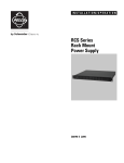
INSTALLATION/OPERATION
WCS Series
Master Power Supply
C654M-E (12/08)
Important Safety Instructions
Prior to installation and use of this product, the following WARNINGS should be observed.
1. Read these instructions.
2. Keep these instructions.
3. Heed all warnings.
4. Follow all instructions.
5. Do not block any ventilation openings. Install in accordance with the manufacturer’s instructions.
6. Do not install near any heat sources, such as radiators, heat registers, stoves, or other apparatus (including amplifiers) that produce heat.
7. Only use attachments/accessories specified by the manufacturer.
8. Use only with the cart, stand, tripod, bracket, or table specified by the manufacturer or sold with the apparatus. When a cart is used, use
caution when moving the cart/apparatus combination to avoid injury from tip-over.
9. Refer all servicing to qualified service personnel. Servicing is required when the apparatus has been damaged in any way, such as power
supply cord or plug is damaged, liquid has been spilled or objects have fallen into the apparatus, the apparatus has been exposed to rain or
moisture, the apparatus does not operate normally, or the apparatus has been dropped.
10. To reduce the risk of shock, do not perform any servicing other than that contained in the operating instructions unless you are qualified to
do so.
11. An ALL-POLE MAINS SWITCH with a contact separation of at least 3 mm in each pole shall be incorporated in the electrical installation of
the building.
12. The installation method and materials should be capable of supporting four times the weight of the unit.
13. Only use replacement parts recommended by Pelco.
14. After replacement/repair of this unit’s electrical components, conduct a resistance measurement between line and exposed parts to verify
the exposed parts have not been connected to line circuitry.
The product and/or manual may bear the following marks:
This symbol indicates that dangerous voltage constituting a risk of electric shock is
present within this unit.
This symbol indicates that there are important operating and maintenance
instructions in the literature accompanying this unit.
CAUTION:
RISK OF ELECTRIC SHOCK.
DO NOT OPEN.
WARNING: Risk of fire; do no interconnect outputs.
Please thoroughly familiarize yourself with the information in this manual prior to installation and operation.
C654M-E (12/08)
3
Description
The WCS Series consists of multi-output 24 VAC outdoor power supplies. These power supplies provide output for one to four cameras
(depending on the dome or pan and tilt) from a single source and come in 20-A capacities. To compensate for voltage losses over long wire runs,
28 VAC outputs are also available. The power supplies allow for 120 or 240 VAC line input. These high-capacity models can handle pan and tilt
and receiver operation in addition to the camera, for integrated systems such as Spectra® and Esprit®.
WCS Series models are available with either glass fuses or self-resetting circuit breakers (poly switches). The following bullets explain the
advantages and disadvantages of each type:
•
Glass fuses provide more protection than circuit breakers because they act faster and are more precise. However, they are designed for
one-time use and must be replaced when they blow.
•
Circuit breakers reset themselves when the fault is corrected, which eliminates the need to replace fuses. However, they react more slowly,
are affected by temperature, and are not as accurate. The amount of current required to trip one can vary as much as 100 percent.
Since circuit breaker models do not require fuses and automatically reset themselves after the fault is corrected, the breakers are not accessible.
Fuses
120/240
24, 28
X
WCS4-20B
4
12
3
120/240
24, 28
X
X
X
X
Power LED
Output Voltage
(VAC)
8
On/Off Switch
Input Voltage
(VAC)
20
Class 2 Output
Max Current Per
Channel (Amps)
4
Surge Protection
Supply Current
(Amps)
WCS4-20
Model Number
Circuit Breakers
Outputs
MODELS
X
X
X
X
APPLICATION EXAMPLES
Table A contains examples of products and the number of units that can be powered by each power supply, and is based on the VA rating of each
product.
Table A. Product Capacity
Product
WCS4-20
WCS4/20B
Traditional Camera (6 VA avg.)
4
4
Outdoor Camclosure (4 VA)
4
4
Outdoor IP Camclosure (21.6 VA)
4
4
Indoor Spectra (30 VA)
4
4
Outdoor Spectra (75 VA)
4
4
Esprit without wiper or IOC/IOP (50 VA)
4
4
without heaters (90 VA)
4
NA
with heaters (140 VA)
3
NA
with heaters and P/T heater blanket (180 VA)
2
NA
PS20-24
4
4
Esprit TI (70 VA)
4
4
ExSite (120 VA)
3
NA
24 V PT780 Legacy System (P/T, Enclosure, Receiver, Camera, Defroster)
4
C654M-E (12/08)
Installation
The following items are supplied:
Qty Description
1
WCS Series Power Supply
4
Output fuses (fuse model)
2
Main fuses (fuse model)
2
Spare output fuses (fuse model)
To install a WCS Series Power Supply, perform the following steps:
1. Decide where to install the unit.
2. Open the lid by removing the screw and twisting the latch.
3. Drill holes in the mounting surface. Use the unit as a template.
4. Attach the unit securely with four fasteners (not supplied) that are at least 1-inch (2.5 cm) long and 1/4-inch (0.64 cm) in diameter. You can
use fasteners up to 5/16-inch (0.80 cm) in diameter.
5. Remove the necessary hole plugs by unscrewing their wing nuts.
6. Install 3/4-inch (1.9 cm) watertight conduit fittings (conduit fittings not provided).
INPUT CONNECTIONS
WARNING: Pelco will not be liable for any damages resulting from incorrect wiring or improper loading of a WCS Series Power Supply.
Units that require a main fuse leave the factory without the fuse installed because they can support both 120 and 240 input voltages. Therefore,
you must install a fuse before operating the unit. Refer to Table B to determine which fuse to install.
Table B. Fuse Determination Table
Main Fuse Value Required Depending on Line
Voltage
Line Voltage
WCS4-20
WCS4-20B
120 VAC
5A
N/A*
240 VAC
3A
N/A*
*Model is not equipped with a primary input fuse;
transformer is protected with thermal breaker.
1. Verify that the on/off switch inside the box is OFF.
WARNING: If 240 VAC power is applied with the selector switch set to 120 VAC, the main fuse will blow (fuse model) or the thermal
breaker will open (breaker model).
2. Install the appropriate fuse in the holder directly below the power switch. Find the fuse in the spare fuse holder. (Extra fuses are supplied
for spares.)
3. Set the input voltage selector switch inside the box to the appropriate line voltage. The switch is set at the factory for 120 VAC line voltage.
4. Attach the 120/240 input wires to the high voltage input connector.
a. Attach the AC high wire to the AC input terminal marked with an “L” (for line).
C654M-E (12/08)
b.
Attach the AC low wire to the AC input terminal marked with an “N” (for neutral).
c.
Attach the ground wire to the stud marked with the ground symbol.
5
OUTPUT CONNECTIONS
WARNING: Under light load conditions and high power line input voltage from the utility company, output voltage from the power supply
(28 VAC taps only) may reach 32 VAC. This voltage can cause over-voltage damage on 24 VAC devices. Keep in mind that certain devices
produce variable loads, including heaters, blowers, and pan and tilt motion; during operation, minimum voltage requirements may create a
light load condition that could cause excessive voltage. Therefore, Pelco recommends using a 28 VAC tap only when the supplied wire size
for the given load causes an unacceptable output voltage on the 24 VAC tap. Refer to Table D on page 8 to determine acceptable situations
for the 28 VAC tap.
Perform the following steps to attach 24 VAC devices to the WCS Series Power Supply:
1. Refer to Table C on page 7 and Table D on page 8 in this manual or the wiring table on the unit’s lid to determine the output connection
needed for your devices.
2. Refer to Figure 1 for the proper connector strip connections.
3. For each device, attach one output wire to the common terminal. Attach the second wire to the appropriate 24 VAC or 28 VAC terminal.
4. When you finish the wiring connections, double-check the installation for safety purposes.
5. Power up the unit with the on/off switch.
6. Use a voltmeter to verify that used outputs are at appropriate voltage levels.
7. Close the lid and secure it using the latch and screw.
6
C654M-E (12/08)
OUTPUT # 1
(24 VAC)
OUTPUT # 4
(28 VAC)
OUTPUT # 2
(24 VAC)
¨
WCS4-20
Master Power Supply
Made in USA
ON
OFF
COM
1
2
3
Power
4
Main
Fuse
28V
L
24V
N
AC Input
GROUND STUD
Figure 1. WCS Unit Wiring Connector Diagram
Table C. Recommended Wiring Distances
The following are the recommended maximum distances (transformer to load) and
are calculated with a 10-percent voltage drop. (Ten percent is generally the
maximum allowable voltage drop for AC-powered devices.) Distances are
calculated in feet; values in parentheses are meters.
Input Voltage
24 VAC
28 VAC
C654M-E (12/08)
Wire Gauge
Total VA
Total VA Consumed
20
18
16
10
283
(86)
451
(137)
716
(218)
20
141
(42)
225
(68)
358
(109)
30
94
(28)
150
(45)
238
(72)
50
56
(17)
90
(27)
143
(43)
10
386
(117)
614
(187)
975
(297)
20
193
(58)
307
(93)
487
(148)
30
128
(39)
204
(62)
325
(99)
50
77
(23)
122
(37)
195
(59)
7
You can use Table D as a guide to determine the necessary wire gauge (AWG) for various cable distances that provide 24 VAC power. Or use it in
a reverse fashion to determine the maximum allowable cable distance for a particular wire gauge. Table D applies when using two-conductor
copper wire with characteristics similar to West Penn 221-227 unshielded cable. Calculations are based on a 10-percent voltage drop (generally
the maximum allowable drop for AC-powered devices).
The minimum acceptable voltage is calculated as follows:
24.0 VAC
–02.4 (10%)
21.6 (Minimum Acceptable Voltage)
The minimum acceptable voltage used to create Table D was 21.6 V. Therefore, the 24-V output has an acceptable range from 24 V down to
21.6 V; the 28-V output’s acceptable range is from 28 V down to 21.6 V.
Table D. Required Wire Gauge
Required Wire Gauge Table (AWG)
400
300
200
100
Outdoor
Spectra
500
CX9000
Rxr’s
600
Indoor
XLS
700
Esprit
Pan/Tilt
800
PT570
Pan/Tilt
900
Indoor
Spectra
1000
P/T480
Pan/Tilt
WIRE
DIST
(feet)
CCD
Camera
Equipment Loads (VA)
10 VA
20 VA
30 VA
40 VA
50 VA
60 VA
70 VA
80 VA
90 VA
100 VA
200 VA
12-14
12
*
*
*
*
*
*
*
*
*
16-18
12-14
12-14
12
*
*
*
*
*
*
*
12-14
12
12
*
*
*
*
*
*
*
*
16-18
14-16
12-14
12
12
*
*
*
*
*
*
12-14
12
12
*
*
*
*
*
*
*
*
16-18
14-16
12-14
12
12
12
*
*
*
*
*
12-16
12
12
12
*
*
*
*
*
*
*
18-20
14-16
12-14
12-14
12
12
*
*
*
*
*
12-16
12
12
12
*
*
*
*
*
*
*
18-20
14-18
14-16
12-14
12-14
12
12
12
*
*
*
12-16
12-14
12
12
12
*
*
*
*
*
*
18-20
16-18
14-16
12-14
12-14
12-14
12
12
12
*
*
12-18
12-14
12
12
12
12
12
*
*
*
*
20-22
16-18
14-18
14-16
12-14
12-14
12-14
12
12
12
*
12-18
12-16
12-14
12
12
12
12
12
12
*
*
20-22
18-20
16-18
14-18
14-16
14-16
12-14
12-14
12-14
12-14
*
12-20
12-18
12-16
12-14
12-14
12
12
12
12
12
*
22
20-22
18-20
16-18
16-18
14-16
14-16
14-16
14-16
12-14
12-14
12-22
12-20
12-18
12-18
12-16
12-16
12-16
12-14
12-14
12-14
12
*
22
20-22
20-22
18-20
18-20
18-20
16-18
16-18
12-14
12-14
XX-XX
Allowable Wire Gauge (AWG) Using 24-V Tap
XX-XX
Allowable Wire Gauge (AWG) Using 28-V Tap
*Distance and Load not recommended for any wire size from 12 to 22 (AWG)
8
C654M-E (12/08)
MAINTENANCE
There are no user-serviceable parts except for the fuses. If the transformer in the unit does not work properly, contact the factory for return
information. Refer to the Product Warranty and Return Information section of this manual.
Clean the outer surface of the power supply with a nonabrasive cleaning cloth and anti-static cleaner. Do not use kerosene or similar substances
that may damage the surface.
SPECIFICATIONS
MECHANICAL
Cable Entry
Hole plugs for 3/4-inch (1.9 cm) conduit
Fuse Size
All fuses are 5 x 20 mm
ELECTRICAL
Input Voltage
120 or 240 VAC, 50/60 Hz
Output Voltage
24/28 VAC
Required Input Current
4.40/2.30 A
Output Fuse Ratings
8A
Output Circuit Breaker Ratings
WCS4-20
WCS4-20B
8A
3A
Input Connectors
Screw-type barrier strips
Output Connectors
Screw-type barrier strips
Input Wire Size
12–16 gauge solid wire
Output Wire Size
12–22 gauge solid or stranded wire
Recommended Wiring Distances
Refer to Table C on page 7.
GENERAL
Construction
Aluminum
Finish
Gray polyester powder coat
Environment
Outdoor, -50° to 122°F (-46° to 50°C)
Dimensions
5.0" D x 12.0" W x 14.5" H
(12.7 x 30.5 x 36.8 cm )
Unit Weight
16.2 lb (7.3 kg)
RATINGS
Meets NEMA Type 4, IP66 standards
(Design and product specifications subject to change without notice.)
C654M-E (12/08)
9
PRODUCT WARRANTY AND RETURN INFORMATION
WARRANTY
Pelco will repair or replace, without charge, any merchandise proved defective in
material or workmanship for a period of one year after the date of shipment.
Exceptions to this warranty are as noted below:
• Five years:
– Fiber optic products
– TW3000 Series unshielded twisted pair (UTP) transmission products
– CC3701H-2, CC3701H-2X, CC3751H-2, CC3651H-2X, MC3651H-2, and
MC3651H-2X camera models
• Three years:
– Pelco-branded fixed camera models (CCC1390H Series, C10DN Series,
C10CH Series, and IP3701H Series)
– EH1500 Series enclosures
– Spectra® IV products (including Spectra IV IP)
– Camclosure® Series (IS, ICS, IP) integrated camera systems
– DX Series digital video recorders, DVR5100 Series digital video recorders,
Digital Sentry ® Series hardware products, DVX Series digital video
recorders, and NVR300 Series network video recorders
– Endura® Series distributed network-based video products
– Genex® Series products (multiplexers, server, and keyboard)
– PMCL200/300/400 Series LCD monitors
• Two years:
– Standard motorized or fixed focal length lenses
– DF5/DF8 Series fixed dome products
– Legacy® Series integrated positioning systems
– Spectra III™, Spectra Mini, Spectra Mini IP, Esprit®, ExSite®, and PS20
scanners, including when used in continuous motion applications.
– Esprit Ti and TI2500 Series thermal imaging products
– Esprit and WW5700 Series window wiper (excluding wiper blades).
– CM6700/CM6800/CM9700 Series matrix
– Digital Light Processing (DLP®) displays (except lamp and color wheel). The
lamp and color wheel will be covered for a period of 90 days. The air filter is
not covered under warranty.
– Intelli-M® eIDC controllers
• One year:
– Video cassette recorders (VCRs), except video heads. Video heads will be
covered for a period of six months.
• Six months:
– All pan and tilts, scanners, or preset lenses used in continuous motion
applications (preset scan, tour, and auto scan modes).
Pelco will warrant all replacement parts and repairs for 90 days from the date of
Pelco shipment. All goods requiring warranty repair shall be sent freight prepaid
to a Pelco designated location. Repairs made necessary by reason of misuse,
alteration, normal wear, or accident are not covered under this warranty.
Pelco assumes no risk and shall be subject to no liability for damages or loss
resulting from the specific use or application made of the Products. Pelco’s liability
for any claim, whether based on breach of contract, negligence, infringement of
any rights of any party or product liability, relating to the Products shall not exceed
the price paid by the Dealer to Pelco for such Products. In no event will Pelco be
liable for any special, incidental, or consequential damages (including loss of use,
loss of profit, and claims of third parties) however caused, whether by the
negligence of Pelco or otherwise.
The above warranty provides the Dealer with specific legal rights. The Dealer may
also have additional rights, which are subject to variation from state to state.
If a warranty repair is required, the Dealer must contact Pelco at (800) 289-9100 or
(559) 292-1981 to obtain a Repair Authorization number (RA), and provide the
following information:
1. Model and serial number
2. Date of shipment, P.O. number, sales order number, or Pelco invoice number
3. Details of the defect or problem
If there is a dispute regarding the warranty of a product that does not fall under
the warranty conditions stated above, please include a written explanation with
the product when returned.
Method of return shipment shall be the same or equal to the method by which the
item was received by Pelco.
RETURNS
To expedite parts returned for repair or credit, please call Pelco at (800) 289-9100
or (559) 292-1981 to obtain an authorization number (CA number if returned for
credit, and RA number if returned for repair) and designated return location.
All merchandise returned for credit may be subject to a 20 percent restocking and
refurbishing charge.
Goods returned for repair or credit should be clearly identified with the assigned
CA or RA number and freight should be prepaid.
11-11-08
The materials used in the manufacture of this document and its components are compliant to the requirements of Directive 2002/95/EC.
This equipment contains electrical or electronic components that must be recycled properly to comply with Directive 2002/96/EC of the European Union
regarding the disposal of waste electrical and electronic equipment (WEEE). Contact your local dealer for procedures for recycling this equipment.
REVISION HISTORY
Manual #
C654M
C654M-A
C654M-B
C654M-C
C654M-D
C654M-E
Date
8/99
8/02
9/03
6/07
7/08
12/08
Comments
Original version.
Added certifications. Revised Important Safeguards and Warnings.
Revised Important Safeguards and Warnings to advise against interconnecting outputs. Revised table of models to show which ones have Class 2 outputs.
Changed input voltage and environment. Revised Table A. Reformatted manual.
Revised Table A, and added the the output circuit breaker rating for WCS4-20B.
Decreased supply current for WCS4-20B in the Models section per CN21624.
Pelco, the Pelco logo, Camclosure, Digital Sentry, Endura, Esprit, ExSite, Genex, Intelli-M, Legacy, and Spectra are registered trademarks of Pelco, Inc.
Spectra III is a trademark of Pelco, Inc.
DLP is a registered trademark of Texas Instruments Incorporated.
© Copyright 2008, Pelco, Inc. All rights reserved.
www.pelco.com
Pelco, Inc. Worldwide Headquarters 3500 Pelco Way Clovis, California 93612 USA
USA & Canada Tel (800) 289-9100 Fax (800) 289-9150
International Tel +1 (559) 292-1981 Fax +1 (559) 348-1120