1
®
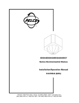
SS20, SS22,
SS2000, SS2002
Series
Discreet
Surveillance
Enclosures
Installation/
Operation Manual
C429M-B (2/98)
UL
®
LISTED
Pelco • 300 W. Pontiac Way, Clovis • CA 93612-5699 USA • Pelco Online @ http://www.pelco.com
In North America and Canada: Tel (800) 289-9100 or FAX (800) 289-9150 • DataFAX (800) 289-9108
International Customers: Tel (1-559) 292-1981 or FAX (1-559) 348-1120 • DataFAX (1-559) 292-0435
CONTENTS
Section
Page
1.0 GENERAL .................................................................................................. 3
1.1 IMPORTANT SAFEGUARDS AND WARNINGS ............................... 3
2.0 DESCRIPTION .......................................................................................... 4
2.1 MODELS ............................................................................................ 4
3.0 INSTALLATION .......................................................................................... 5
3.1 CONDUCTOR AND CABLE REQUIREMENTS ................................ 5
3.1.1Recommended Mounts .............................................................. 5
3.1.2Recommended Cables .............................................................. 5
3.2 CONNECTOR ASSEMBLY ................................................................ 9
3.3 MOUNTING ......................................................................................11
3.4 DOME INSTALLATION ..................................................................... 12
4.0 EXPLODED ASSEMBLY DIAGRAM .........................................................13
5.0 ADJUSTMENTS ....................................................................................... 15
6.0 MAINTENANCE ........................................................................................16
7.0 SPECIFICATIONS .................................................................................... 17
8.0 WARRANTY AND RETURN INFORMATION ........................................... 20
LIST OF ILLUSTRATIONS
Figure
1
2
3
4
5
6
7
8
9
10
11
Page
SS20/SS22/SS2000/SS2002 Dimension Drawing ............................. 4
SS2000/SS2000-SL/SS2002-SL Wiring Diagram .............................. 6
SS2000-PP Wiring Diagram .............................................................. 7
SS2000SL-PP Wiring Diagram ......................................................... 8
Connector Assembly .......................................................................... 9
Mating Cable Assembly Configuration (non-PP Versions) ................ 10
Mating Cable Assembly Configuration (PP Versions) ....................... 10
Mounting Configurations ................................................................... 11
SS2000/SS2002 Exploded Assembly Diagram ................................ 14
Limit Stop Locations ......................................................................... 15
Tilt Limit Stop Modifications .............................................................. 15
LIST OF TABLES
Table
A
Page
SS2000/SS2002 Exploded Assembly Diagram ................................ 13
REVISION HISTORY
Manual #
Date
Comments
C429M-A
10/94
C429M-B
7/96
8/96
Wire colors revised on figures 2-4, 6 and 7. (Pin 8 Figure 2; Pins 8 & 23 - Figures 3 and 4; Pins 8, 11, 12,
13 - Figures 6 and 7.)
Revised to include new models SS22 and SS2002-SL.
Revised Section 5.0, Mechanical Parts List, regarding
lower dome part numbers and quantities of velcro.
Corrected wiring for pins 19 and 27 in Figure 7 per ECO
97-235.
Revised Section 6.0, Maintenance. Changed manual to
new style.
7/97
2/98
2
Pelco Manual C429M-B (2/98)
1.0 GENERAL
1.1 IMPORTANT SAFEGUARDS AND WARNINGS
CAUTION: This device is
designed to operate at 24
volts AC power. Input voltages must not exceed 28
volts or drop below 22 volts,
or else damage the the
motors will occur. Should
you need technical assistance, please call (800) 2899100.
Prior to installation and use of this product, the following WARNINGS should be
observed.
1.
Installation and servicing should only be done by Qualified Service Personnel
and conform to all Local codes.
2.
Unless the unit is specifically marked as a NEMA Type 3, 3R, 3S, 4, 4X, 6, or
6P enclosure, it is designed for indoor use only and it must not be installed
where exposed to rain and moisture.
3.
Only use replacement parts recommended by Pelco.
4.
After replacement/repair of this unit’s electrical components, conduct a resistance measurement between line and exposed parts to verify the exposed
parts have not been connected to line circuitry.
5.
The installation method and materials should be capable of supporting four
times the weight of the enclosure, pan/tilt, camera and lens combination.
The product and/or manual may bear the following marks:
This symbol indicates that dangerous voltage constituting a
risk of electric shock is present within this unit.
This symbol indicates that there are important operating and
maintenance instructions in the literature accompanying this
unit.
CAUTION:
RISK OF
ELECTRIC SHOCK.
DO NOT OPEN.
CAUTION:
TO REDUCE THE RISK OF ELECTRICAL SHOCK,
DO NOT REMOVE COVER. NO USERSERVICEABLE PARTS INSIDE. REFER SERVICING
TO QUALIFIED SERVICE PERSONNEL.
Please thoroughly familiarize yourself with the information
in this manual prior to installation and operation.
Pelco Manual C429M-B (2/98)
3
2.0 DESCRIPTION
Pelco’s SS20/SS22/SS2000/SS2002 Series domes are full-sphere, discreet surveillance enclosures designed to be suspended from ceilings and to compliment
the interior design of businesses, hotels, and offices.
The black opaque (or chrome) lower dome effectively camouflages a CTTV security/
surveillance system without compromising the quality of the video picture.
Options for the SS2000/SS2002 include a standard pan/tilt, pan/tilt with continuous
360° pan rotation (SL), or preset pan/tilt available in either the standard or SL version pan/tilt. All pan/tilts are pre-wired for all system functions, dramatically reducing installation time. The use of standard manufactured components increases the
reliability and serviceability of the system.
2.1 MODELS
SS20
Full sphere discreet surveillance dome with fixed mount for
CCD type cameras. 14" black opaque lower dome with 1 f-stop
light loss.
SS22
Same as SS20 except supplied with a 14" chrome opaque
lower dome with 2 f-stop light loss.
SS2000
Full sphere discreet surveillance dome with high speed integral
pan/tilt for CCD type cameras. 14" black opaque lower dome
with 1 f-stop light loss.
SS2000-PP
Full sphere discreet surveillance dome with high speed integral
pan/tilt with presets (/PP option) for CCD type cameras. 14"
black opaque lower dome with 1 f-stop light loss.
SS2000-SL
Same as SS2000 except supplied with 360° continuous pan
rotation
SS2002-SL
Same as SS2000-SL except supplied with a 14" chrome
opaque lower dome with 2 f-stop light loss.
SS2000SL-PP
Same as SS2000-PP except supplied with 360° continuous
pan rotation.
NOTE: VALUES IN PARENTHESIS ARE CENTIMETERS; ALL OTHERS ARE INCHES.
Figure 1. SS20/SS22/SS2000/SS2002 Dimension Drawing
4
Pelco Manual C429M-B (2/98)
3.0 INSTALLATION
Save the shipping carton and plastic packing in case the unit has to be returned for
credit or repair.
3.1 CONDUCTOR AND CABLE REQUIREMENTS
NOTE: The following are cable requirements. A relay box (RB24) is
available to extend the operating distance up to 13,000 feet (3,962 m) over
16 Awg wire.
A minimum of 11 conductors plus coax is required, which includes common requirements for motorized zoom lens and camera AC power.
Non-PP Models
18 Awg
16 Awg
14 Awg
11 Conductor
12 Conductor*
227 ft (82m)
432 ft (131 m)
690 ft (210 m)
494 ft (150 m)
785 ft (239 m)
1,253 ft (381 m)
17 Conductor
18 Conductor*
227 ft (82m)
432 ft (131 m)
690 ft (210 m)
494 ft (150 m)
785 ft (239 m)
1,253 ft (381 m)
PP Models
18 Awg
16 Awg
14 Awg
* Using 2 conductors for common
Calculations are based on a 10% cable loss with both motors running.
3.1.1 Recommended Mounts
MRWA
MRCA
Wall mount adapter
Ceiling mount adapter
3.1.2 Recommended Cables
C1906
C1925
Pelco Manual C429M-B (2/98)
Pretested 6-foot cable with video coax
Pretested 25-foot cable with video coax
5
Figure 2. SS2000/SS2000-SL/SS2002-SL Wiring Diagram
6
Pelco Manual C429M-B (2/98)
Figure 3. SS2000-PP Wiring Diagram
Pelco Manual C429M-B (2/98)
7
Figure 4. SS2000SL-PP Wiring Diagram
8
Pelco Manual C429M-B (2/98)
3.2 CONNECTOR ASSEMBLY
NOTE: Contacts cannot be removed
from the connector without the use
of an AMP extraction tool, part number ZT305183 (for 9-, 14-, or 16-pin
connector) or ZT91067-2 (for 28-pin
connector), which is available from
Pelco.
To install and test the SS2000/SS2002 Series dome you will need to assemble the
connector parts provided. Fabricate the interconnecting cable as outlined below
(see Figure 5):
1.
Slide the cable clamp (part A , item 1) over the cable with the threaded end
facing the connector (item 5).
2.
If the cable has a diameter less than 1/2 inch (1.3 cm), slide the rubber boot
(item 2) over the end of the cable and press inside the cable clamp to form a
good seal.
3.
Strip back the cable jacket approximately 1-1/4 inches (3.2 cm) and separate
the individual conductors.
4.
The contact pins supplied with the mating connector are the “crimp” type which
may also be soldered if you so desire.
5.
After crimping or soldering the contacts, push them into the proper holes in
the connector until they snap in place.
6.
Slide part A of the cable clamp toward the connector and screw the parts
together. Attach part B (item 1) onto part A and connect both parts with the
screws provided.
7.
Connect the cable assembly to the unit and seat the connector by twisting the
locking collar until it snaps into position.
8.
For ease of installation, a mating cable assembly is supplied with the domes
to extend the cable from the pan/tilt. Please refer to Figures 6 and 7 for wiring
(pin locations and color codes).
Figure 5. Connector Assembly
Pelco Manual C429M-B (2/98)
9
CABLE, 12 COND. @ 6'
WIR201912
COAX @ 6'
WIRRG59/U9259
CONCP88-2
14-POS RECEPTACLE
CON206403-3
CRIMP SOCKET
CON66105-2
3
2
7
6
5
10
9
13
POSITION
1
2
3
4
5
6
7
8
9
10
11
12
13
14
1
11
14
CABLE CLAMP
CON206070-1
4
8
12
FRONT VIEW
14-PIN CONNECTOR
COLOR
BROWN
CORE COAX
RED
SHIELD COAX
YELLOW
ORANGE
BLUE
GREEN
WHITE
BLACK
TAN (OR BLK/WHT)
PINK (OR RED/WHT)
VIOLET
GRAY
FUNCTION
COMMON/PAN AND TILT
VIDEO
LEFT
VIDEO
DOWN
UP
RIGHT
GROUND
AC HIGH, CAMERA
IRIS
FOCUS
ZOOM
COMMON, LENS
AC LOW, CAMERA
Figure 6. Mating Cable Assembly Configuration (non-PP Versions)
CABLE, 12 COND. @ 6'
WIR201912
CABLE, 9 COND. @ 6'
WIR220709
28-POS RECEPTACLE
CON205839-3
CRIMP SOCKET
CON1-66504-0
NO.
3
1
8
4
14
9
20
15
25
21
28
26
FRONT VIEW
28-PIN CONNECTOR
1
2
3
4
5
6
7
8
9
10
11
12
13
14
COLOR
BROWN
CORE COAX
RED
SHIELD COAX
YELLOW
ORANGE
BLUE
GREEN
WHITE
BLACK
TAN (OR BLK/WHT)
PINK (OR RED/WHT)
VIOLET
GRAY
COAX @ 6'
WIRRG174/U
CONCPM88-174
CABLE CLAMP'
CON206070-1
FUNCTION
COMMON/PAN AND TILT
VIDEO
LEFT
VIDEO
DOWN
UP
RIGHT
GROUND
AC HIGH, CAMERA
IRIS
FOCUS
ZOOM
COMMON, LENS
AC LOW, CAMERA
12 Conductor Cable
Coax
NO.
15
16
17
18
19
20
21
22
23
24
25
26
27
28
COLOR
——
——
BLUE
BROWN
WHT/ORG/BLK
RED
YELLOW
BLACK
VIOLET
WHITE
——
——
——
——
FUNCTION
——
——
HIGH, PRESET
COMMON, PRESET
SPARE
ZOOM, PRESET
FOCUS, PRESET
PAN, PRESET
TILT, PRESET
PAN, PRESET (SL only)
——
——
——
——
9 Conductor Cable
Figure 7. Mating Cable Assembly Configuration (PP Versions)
10
Pelco Manual C429M-B (2/98)
3.3 MOUNTING
The SS2000/SS2002 enclosure is designed to be suspended from a suitable length
of 1-1/2" pipe threaded at both ends. This pipe can be interfaced to either a Pelco
MRWA wall adapter, MRCA ceiling adapter, or coupled to a longer length of pipe.
Refer to Figure 8 for mounting configurations.
STRUCTURAL CEILING MOUNTING
DROP CEILING MOUNTING
WALL MOUNTING
Figure 8. Mounting Configurations
Pelco Manual C429M-B (2/98)
11
3.4 DOME INSTALLATION
To install your dome system, perform the following steps (refer to Figure 9):
NOTE: The small hole in the upper
dome (for safety chain attachment)
should be positioned at the back (connector) end of the camera.
NOTE: For SS20/SS22 mounting, refer to steps 1, 2, 6, 7, 8, and 10. For
step 9, adjust the tilt and rotation, and
tighten all hardware.
12
1.
Select the appropriate pipe length and mounting method. If the MRCA or MRWA
mount is used, tighten the pipe to approximately 30 ft lb, then tighten the 8-32
screw in the pipe nut to lock the pipe threads. Slide the upper dome onto the
pipe and lock it out of the way with a suitable retainer.
2.
Screw the mounting flange (item 4) onto the pipe and tighten securely (approximately 20 ft lb). Tighten the 8-32 screw in the pipe nut to lock the pipe
threads.
3.
Align the three-hole pattern in the pan spindle with the holes in the lower
bracket (item 5), and attach with 1/4"-20 x 5/8" hex head bolts and lock washers provided. Tighten firmly.
4.
Attach the upper (drive) bracket (item 3) to the bottom (spindle side) of the
pan/tilt using four (4) 8-32 x 1/2" pan head screws and lock washers provided.
Refer to Figure 9 for proper orientation.
5.
Connect the installation cable to the pan/tilt and feed it through the center of
the 1-1/2" pipe. Pull the cable and connector back up into the pipe so that it
does not get caught on the rotating parts.
6.
Assemble the lower bracket and pan/tilt to the mounting flange (item 4) using
1/4" x 5/8" hex head bolts and flat washers.
7.
Install the camera/lens assembly onto the tilt table of the pan/tilt. Connect the
proper cables.
8.
Remove the retainer from the upper dome and lower it until it seats itself on
the drive bracket.
9.
Turn the system “ON” and rotate the pan/tilt. Check for cable interference. Tilt
the camera up and down and check for clearance of all moving parts.
10. After all tests have been done and the system is functioning properly, attach
the safety chain to the upper dome with the fasteners provided. Install the
lower dome and align the viewing window.
11. Check for sufficient clearance between the lens and the lower dome.
Pelco Manual C429M-B (2/98)
4.0 EXPLODED ASSEMBLY DIAGRAM
Table A. SS2000/SS2002 Exploded Assembly Diagram
Item
Qty
Description
1
2
1
1
3
4
5
6
7
10
1
1
1
48
50
56
1
1
1
1
11
12
1
1
Dome, upper
Dome, lower, Black (Opaque)
Dome, lower, Chrome (Opaque)
Bracket, drive
Bracket, upper
Bracket, lower
Velcro, black, 5/8" wide x inch (not shown)
Velcro, black, 5/8" wide x inch (not shown) (SS22 & SS2002-SL)
Velcro, black, 5/8" wide x inch (not shown) (SS20 & SS2000 Series)
Chain, safety
Pan/tilt assembly
Fixed mount assembly (Model SS20 only)
Cable assembly, 14-pin x 6' (For SS2000 and SS2000-SL)
Cable assembly, 28-pin x 6' (SS2000-PP and SS2000SL-PP)
Pipe, mounting
Snap body for safety chain (not shown)
8
9
Part Number
SS200010000
SS200010001*
SS2012000*
SS20004007COMP
SS20001000COMP
SS20004008COMP
TV10002
TV10003
TV10003
SB2511000
PT2500
SS20001001ASSY
SS1000ASSY
SS1001ASSY
SS34002COMP
SB2511001
* Part number is for the dome only. To order a complete lower dome assembly, specify the part numbers SS20004300COMP (black)
and SS20200COMP (chrome). These part numbers include items 2, 7, 8, and 12.
Pelco Manual C429M-B (2/98)
13
Figure 9. SS2000/SS2002 Exploded Assembly Diagram
14
Pelco Manual C429M-B (2/98)
5.0 ADJUSTMENTS
To adjust the pan/tilt limits, perform the following steps. Refer to Figure 10 for limit
stop locations.
CAUTION: Do not attempt
to adjust limit stops when
the pan/tilt is in operation.
Damage to the equipment
can result. Do not operate
equipment without limit
stops. SL models are supplied without pan limit stops,
therefore, no adjustments
are necessary.
Figure 10. Limit Stop Locations
Pelco Manual C429M-B (2/98)
Factory pan limits are set to 0-355° and tilt limits are set to 0-90° (horizontal to
vertical). Under normal conditions, the tilt limits should not have to be reset. To
adjust limit stops, perform the following steps:
1.
Pan to the right using the joystick control until the desired pan limit is reached.
Adjust the pan limit stop until the actuator clicks. Lock the limit into position.
2.
Pan to the desired left position, adjust the pan limit stop until the actuator
clicks, and lock into position.
3.
Pan to the left and right to verify exact positioning and tighten both stops securely.
4.
The tilt limit is designed to allow for 0-90° travel (horizontal to vertical). The tilt
can be adjusted to any point between horizontal and vertical, but must never
exceed these boundaries.
5.
To alter the factory-set tilt limit, bend the actuator stops on the micro switches.
Move the tilt table to the desired position and adjust the actuators until the
switch clicks, lock into position (see Figure 11).
6.
Tilt up and down to verify exact positioning.
Figure 11. Tilt Limit Stop Modifications
15
6.0 MAINTENANCE
Clean the acrylic lower dome as necessary to maintain a clear picture. Be careful
not to scratch the surfaces of the dome.
Exterior Surface - Clean the dome's exterior surface with a nonabrasive cleaning
cloth and cleaning agent that is safe for acrylic plastic. Either liquid or spray cleaner/
wax suitable for fine furniture is acceptable.
Interior Surface (Except Chrome) - Clean the same as the exterior surface.
Interior Surface (Chrome) - The inside surface of a chrome dome is easily scratched.
Use the following precautions to maintain the dome's surface.
a.
Always handle the dome from the outside of its circular flange.
b.
Never touch the coated inside surface. The acid in your fingerprints will eventually etch the coating if the fingerprints are not carefully removed according
to the recommended cleaning procedure in item “e.”
c.
If dust or other contaminants accumulate on the dome's interior, remove the
debris with compressed air. Compressed air cans are available from photographic equipment or electronic supply dealers.
d.
If heavy residue accumulates and cannot be removed with air pressure, rinse
with water and immediately dry with air pressure so that water spots will not
remain. Avoid wiping the coated surface with direct hand pressure - it will easily abrade unless extreme care is taken. Once scratched, the dome cannot be
recoated.
e.
If internal wiping is necessary, avoid hand rubbing. Instead, make a wick as
follows:
Use a very soft paper towel. Roll a section into a tightly wound tube. Tear the
tube in half, and wet the fuzzy end of the wick with a solution of isopropyl
alcohol diluted with water. Hold the dome with its opening facing downward
and wipe the interior of the dome with the wet end of the wick. Use a circular
motion, starting from the outside and spiraling into the center. Use a new wick
for each two passes over the dome.
16
Pelco Manual C429M-B (2/98)
7.0 SPECIFICATIONS
ELECTRICAL
Input Voltage:
24 VAC required for pan/tilt
Running Current
Pan:
Tilt:
0.31 amp (7.44 vA)
0.38 amp (9.12 vA)
Connectors
Pan/Tilt:
Lens:
Video:
Amp CPC type (mate supplied)
Hirschmann MAB6100
BNC
Camera Power:
Spade lugs
Motors:
Two-phase induction type, instantaneous reversing
Limit Switches
Pan:
Tilt:
5 amp, (external adjustment)
5 amp, (external adjustment)
Conductor
Requirements
as listed, plus
coax cable:
Non-PP models: Pan/tilt (5 plus ground), Lens (4), Camera AC (2)
PP models:
Pan/tilt (9 plus ground), Lens (6), Camera AC (2)
MECHANICAL
Pelco Manual C429M-B (2/98)
Pan:
0-355° movement in horizontal plane (Models SS2000, SS2000-PP)
360° continuous rotation (Models SS2000-SL, SS2000SL-PP)
Pan Speed:
24°/sec ± 1° (no load condition)
Tilt:
-90° from horizontal plane
Tilt Speed:
12°/sec ± .5° (no load condition)
Maximum Load:
10 lb (4.6 kg)
Gearing:
Chain and direct drive
Bearings
Pan:
Tilt:
Heavy duty ball bearing and Oilite bronze bushing
Oilite bronze bushing
Braking:
Friction
17
GENERAL
Maximum Camera/
Lens Length:
12.5 inches (31.75 cm)
Ambient
Temperature
Range:
Construction
Upper dome:
Lower dome:
Dimensions:
35°F to 120°F (1.6°C to 48.8°C)
Black, high-impact plastic, ABS
Acrylic hemisphere with distortion-free viewing window with
light attenuation factor of 1 f-stop; model SS2002-SL has 2 fstop light attenuation factor. Rotates with pan/tilt and camera/
lens
See Figure 1
Weight
Model SS20/
SS22:
7 lb
All other models: 14 lb 13 oz
Shipping Weight
Model SS20/
SS22:
8 lb
All other models: 17 lb
(Design and product specifications subject to change without notice.)
18
Pelco Manual C429M-B (2/98)
NOTES
Pelco Manual C429M-B (2/98)
19
8.0 WARRANTY AND RETURN INFORMATION
WARRANTY
Pelco will repair or replace, without charge, any merchandise proved defective in
material or workmanship for a period of one year after the date of shipment. Exceptions to this warranty are as noted below:
•
•
•
•
•
•
Three years on Genex™ Series multiplexers.
Two years on all standard motorized and fixed focal length lenses.
Two years on Legacy®, Intercept®, PV1000 Series, CM6700/CM8500/CM9500/
CM9750/CM9760 Matrix, Spectra™, DF5 Series and DF8 Fixed Dome products.
Two years on WW5700 series window wiper (excluding wiper blades).
Two years on cameras.
Six months on all pan and tilts, scanners or preset lenses used in continuous
motion applications (that is, preset scan, tour and auto scan modes).
Pelco will warranty all replacement parts and repairs for 90 days from the date of
Pelco shipment. All goods requiring warranty repair shall be sent freight prepaid to
Pelco, Clovis, California. Repairs made necessary by reason of misuse, alteration,
normal wear, or accident are not covered under this warranty.
Pelco assumes no risk and shall be subject to no liability for damages or loss resulting from the specific use or application made of the Products. Pelco’s liability for any
claim, whether based on breach of contract, negligence, infringement of any rights
of any party or product liability, relating to the Products shall not exceed the price
paid by the Dealer to Pelco for such Products. In no event will Pelco be liable for any
special, incidental or consequential damages (including loss of use, loss of profit
and claims of third parties) however caused, whether by the negligence of Pelco or
otherwise.
The above warranty provides the Dealer with specific legal rights. The Dealer may
also have additional rights, which are subject to variation from state to state.
If a warranty repair is required, the Dealer must contact Pelco at (800) 289-9100 or
(559) 292-1981 to obtain a Repair Authorization number (RA), and provide the
following information:
1.
2.
3.
Model and serial number
Date of shipment, P.O. number, Sales Order number, or Pelco invoice number
Details of the defect or problem
If there is a dispute regarding the warranty of a product which does not fall under
the warranty conditions stated above, please include a written explanation with the
product when returned.
Ship freight prepaid to:
Pelco
300 West Pontiac Way
Clovis, CA 93612-5699
Method of return shipment shall be the same or equal to the method by which the
item was received by Pelco.
RETURNS
In order to expedite parts returned to the factory for repair or credit, please call the
factory at (800) 289-9100 or (559) 292-1981 to obtain an authorization number (CA
number if returned for credit, and RA number if returned for repair). Goods returned
for repair or credit should be clearly identified with the assigned CA/RA number and
freight should be prepaid. All merchandise returned for credit may be subject to a
20% restocking and refurbishing charge.
® Pelco and the Pelco logo are registered
trademarks of Pelco.
© Copyright 1998, Pelco. All rights
reserved.
20
Ship freight prepaid to:
Pelco
300 West Pontiac Way
Clovis, CA 93612-5699
Pelco Manual C429M-B (2/98)