1
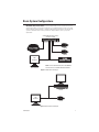
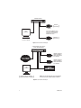
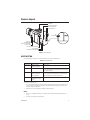
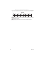
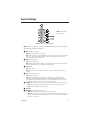
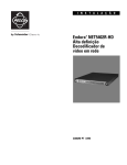
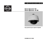
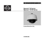
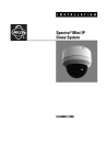
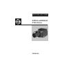
I N S T A L L A T I O N
IP3701H-2 and IP3701H-2X
IP Color Camera
C2941M (8/07)
Contents
Important Safety Instructions. . . . . . . . . . . . . . . . . . . . . . . . . . . . . . . . . . . . . . . . . . . . . . . . . . . . . . . . . . . . . 4
Regulatory Notices . . . . . . . . . . . . . . . . . . . . . . . . . . . . . . . . . . . . . . . . . . . . . . . . . . . . . . . . . . . . . . . . . . . . . 5
Description . . . . . . . . . . . . . . . . . . . . . . . . . . . . . . . . . . . . . . . . . . . . . . . . . . . . . . . . . . . . . . . . . . . . . . . . . . . 6
Models . . . . . . . . . . . . . . . . . . . . . . . . . . . . . . . . . . . . . . . . . . . . . . . . . . . . . . . . . . . . . . . . . . . . . . . . . 6
Basic System Configurations . . . . . . . . . . . . . . . . . . . . . . . . . . . . . . . . . . . . . . . . . . . . . . . . . . . . . . . . . . . . . 7
Camera Layout . . . . . . . . . . . . . . . . . . . . . . . . . . . . . . . . . . . . . . . . . . . . . . . . . . . . . . . . . . . . . . . . . . . . . . . . 9
Reset Button . . . . . . . . . . . . . . . . . . . . . . . . . . . . . . . . . . . . . . . . . . . . . . . . . . . . . . . . . . . . . . . . . . . . . 9
Installation . . . . . . . . . . . . . . . . . . . . . . . . . . . . . . . . . . . . . . . . . . . . . . . . . . . . . . . . . . . . . . . . . . . . . . . . . . 10
Lens Mounting . . . . . . . . . . . . . . . . . . . . . . . . . . . . . . . . . . . . . . . . . . . . . . . . . . . . . . . . . . . . . . . . . . 10
Camera Mounting. . . . . . . . . . . . . . . . . . . . . . . . . . . . . . . . . . . . . . . . . . . . . . . . . . . . . . . . . . . . . . . . 10
Wiring Tables . . . . . . . . . . . . . . . . . . . . . . . . . . . . . . . . . . . . . . . . . . . . . . . . . . . . . . . . . . . . . . . . . . . . . . . . 11
Cat5 Cable . . . . . . . . . . . . . . . . . . . . . . . . . . . . . . . . . . . . . . . . . . . . . . . . . . . . . . . . . . . . . . . . . . . . . 11
24 VAC and BNC Connections (optional) . . . . . . . . . . . . . . . . . . . . . . . . . . . . . . . . . . . . . . . . . . . . . . 11
Lens Setup and Focus Procedures . . . . . . . . . . . . . . . . . . . . . . . . . . . . . . . . . . . . . . . . . . . . . . . . . . . . . . . .
Video Drive Auto Iris Lens . . . . . . . . . . . . . . . . . . . . . . . . . . . . . . . . . . . . . . . . . . . . . . . . . . . . . . . . .
Direct Drive DC Auto Iris Lens . . . . . . . . . . . . . . . . . . . . . . . . . . . . . . . . . . . . . . . . . . . . . . . . . . . . . .
Fixed Lens, No Iris . . . . . . . . . . . . . . . . . . . . . . . . . . . . . . . . . . . . . . . . . . . . . . . . . . . . . . . . . . . . . . .
Manual Iris Lens . . . . . . . . . . . . . . . . . . . . . . . . . . . . . . . . . . . . . . . . . . . . . . . . . . . . . . . . . . . . . . . . .
Zoom Lens . . . . . . . . . . . . . . . . . . . . . . . . . . . . . . . . . . . . . . . . . . . . . . . . . . . . . . . . . . . . . . . . . . . . .
13
13
13
13
13
13
Back Focus Adjustment . . . . . . . . . . . . . . . . . . . . . . . . . . . . . . . . . . . . . . . . . . . . . . . . . . . . . . . . . . . . . . . . 14
Switch Settings . . . . . . . . . . . . . . . . . . . . . . . . . . . . . . . . . . . . . . . . . . . . . . . . . . . . . . . . . . . . . . . . . . . . . . 15
Dynamic Range and EDR . . . . . . . . . . . . . . . . . . . . . . . . . . . . . . . . . . . . . . . . . . . . . . . . . . . . . . . . . . . . . . . 17
Troubleshooting . . . . . . . . . . . . . . . . . . . . . . . . . . . . . . . . . . . . . . . . . . . . . . . . . . . . . . . . . . . . . . . . . . . . . . 18
Specifications . . . . . . . . . . . . . . . . . . . . . . . . . . . . . . . . . . . . . . . . . . . . . . . . . . . . . . . . . . . . . . . . . . . . . . . . 20
C2941M (8/07)
3
Important Safety Instructions
1. Read these instructions.
2. Keep these instructions.
3. Heed all warnings.
4. Follow all instructions.
5. Do not use this apparatus near water.
6. Do not block any ventilation openings. Install in accordance with the manufacturer’s instructions.
7. Only use attachments/accessories specified by the manufacturer.
8. Apparatus shall not be exposed to dripping or splashing and that no objects filled with liquids, such
as vases shall be placed on the apparatus.
9. Installation should be done only by qualified personnel and conform to all local codes.
10. Unless the unit is specifically marked as a NEMA Type 3, 3R, 3S, 4, 4X, 6, or 6P enclosure, it is
designed for indoor use only and it must not be installed where exposed to rain and moisture.
11. Use only installation methods and materials capable of supporting four times the maximum
specified load.
12. Use stainless steel hardware to fasten the mount to outdoor surfaces.
13. Only use replacement parts recommended by Pelco.
14. After replacement/repair of this unit’s electrical components, conduct a resistance measurement
between the line and exposed parts to verify the exposed parts have not been connected to the line
circuitry.
4
C2941M (8/07)
Regulatory Notices
This device complies with Part 15 of the FCC Rules. Operation is subject to the following two conditions:
(1) this device may not cause harmful interference, and (2) this device must accept any interference
received, including interference that may cause undesired operation.
RADIO AND TELEVISION INTERFERENCE
This equipment has been tested and found to comply with the limits of a Class B digital device, pursuant to
Part 15 of the FCC Rules. These limits are designed to provide reasonable protection against harmful
interference in a residential installation. This equipment generates, uses, and can radiate radio frequency
energy and, if not installed and used in accordance with the instructions, may cause harmful interference
to radio communications. However there is no guarantee that the interference will not occur in a particular
installation. If this equipment does cause harmful interference to radio or television reception, which can
be determined by turning the equipment off and on, the user is encouraged to try to correct the
interference by one or more of the following measures:
•
Reorient or relocate the receiving antenna.
•
Increase the separation between the equipment and the receiver.
•
Connect the equipment into an outlet on a circuit different from that to which the receiver is
connected.
•
Consult the dealer or an experienced radio/TV technician for help.
You may also find helpful the following booklet, prepared by the FCC: “How to Identify and Resolve
Radio-TV Interference Problems.” This booklet is available from the U.S. Government Printing Office,
Washington D.C. 20402.
Changes and Modifications not expressly approved by the manufacturer or registrant of this equipment
can void your authority to operate this equipment under Federal Communications Commission’s rules.
This Class B digital apparatus complies with Canadian ICES-003.
Cet appareil numérique de la classe B est conforme à la norme NMB-003 du Canada.
Video Quality Caution
FRAME RATE NOTICE REGARDING USER-SELECTED OPTIONS
Pelco systems are capable of providing high quality video for both live viewing and playback. However,
the systems can be used in lower quality modes, which can degrade picture quality, to allow for a slower
rate of data transfer and to reduce the amount of video data stored. The picture quality can be degraded
by either lowering the resolution, reducing the picture rate, or both. A picture degraded by having a
reduced resolution may result in an image that is less clear or even indiscernible. A picture degraded by
reducing the picture rate has fewer frames per second, which can result in images that appear to jump or
move more quickly than normal during playback. Lower frame rates may result in a key event not being
recorded by the system.
Judgment as to the suitability of the products for user’s purposes is solely the user’s responsibility. Users
shall determine the suitability of the products for their own intended application, picture rate and picture
quality. In the event user intends to use the video for evidentiary purposes in a judicial proceeding or
otherwise, user should consult with its attorney regarding any particular requirements for such use.
C2941M (8/07)
5
Description
The IP3701H-2 and IP3701H-2X are high resolution, color video cameras with a built-in 100Base-TX
network interface for live streaming to a standard Web browser (Microsoft® Internet Explorer® or
Firefox®). The camera features open architecture connectivity for third-party software recording solutions
and is also Endura Enabled™ to record, manage, configure, and view multiple live streams.
The camera also includes built-in Power over Ethernet (PoE), which supplies power to the camera through
the network. If PoE is not available, the camera is pre-wired for 24 VAC.
Before installing your camera, thoroughly familiarize yourself with the information in this manual.
MODELS
IP3701H-2
IP3701H-2X
6
High resolution, 480 TV lines, SuperHAD™ CCD, minimum illumination of 0.5 lux at f/1.2 and
40 IRE, NTSC
High resolution, 470 TV lines, SuperHAD CCD, minimum illumination of 0.5 lux at f/1.2 and
40 IRE, PAL
C2941M (8/07)
Basic System Configurations
IMPORTANT NOTE. PLEASE READ. The network implementations in this document are shown as
general representations only and are not intended to show detailed network topologies. Your actual
network will differ, requiring changes or perhaps additional network equipment to accommodate the
systems as illustrated. Please contact your local Pelco Representative to discuss your specific
requirements.
CABLE MODEM ROUTER / SWITCH
WITH DHCP SERVER
CAMERA
TCP / IP / INTERNET
CAMERA
3rd PARTY
RECORDING SOLUTION
WEB
BROWSER
DHCP NETWORK
NOTE: FOR A SECURE NETWORK, PELCO RECOMMENDS
PLACING THE IP3701H CAMERA BEHIND A FIREWALL.
Figure 1. DHCP Network Example
ENDURA
WEB
BROWSER
CAMERA
Figure 2. Endura Network Example
C2941M (8/07)
7
NETWORK SWITCH
(
EXAMPLE
169.254.200.0
)
CAMERA
IF NOT DHCP, CAMERA CYCLES
THROUGH IP ADDRESS RANGE
169.254.200.0 - 169.254.200.255;
NETMASK 255.255.0.0
WEB
BROWSER
(
PRIVATE NETWORK
PC ACTS AS SERVER
EXAMPLE
169.254.200.1
)
CAMERA
Figure 3. Private Network Example
CABLE MODEM ROUTER / SWITCH
(DHCP SERVER DISABLED)
CAMERA
TCP / IP / INTERNET
CAMERA
CAMERA 2 FIXED BUT
UNIQUE IP ADDRESS;
SAME SUBNET MASK
AS COMPUTER
3rd PARTY
RECORDING SOLUTION
WEB
BROWSER
(
CAMERA 1 FIXED BUT
UNIQUE IP ADDRESS;
SAME SUBNET MASK
AS COMPUTER
STATIC NETWORK
FIXED BUT UNIQUE IP ADDRESS;
SAME SUBNET MASK AS CAMERAS
)
NOTE: FOR A SECURE NETWORK, PELCO RECOMMENDS
PLACING THE IP3701H CAMERA BEHIND A FIREWALL.
Figure 4. Static Network Example
8
C2941M (8/07)
Camera Layout
TOP MOUNT
LENS LEVEL ADJUSTMENT
NETWORK CONNECTOR
POWER CONNECTOR
LEDs
RESET BUTTON
BACK FOCUS
ADJUSTMENT RING
BACK FOCUS ADJUSTMENT
LOCKING SCREW
BNC VIDEO SERVICE CONNECTOR
LENS CONNECTOR
DIP SWITCHES (COVER REMOVED)
Figure 5. Camera Layout
RESET BUTTON
Use the reset button located on the side of the camera to access the following modes:
Table A. Reset LED Status
Mode
Configuration
Reboot
Reset
Cancel
Function
Starts reset LED
selection sequence.
Restarts the unit.
Resets unit to factory
default settings and
then restarts unit.
Cancels any
configuration or reset
action.
Unit Status Indicator Light
Flashes green.
Flashes green and red simultaneously, when entering this
mode. The LED then flashes green when mode is selected
and during the reboot.
Flashes red when entering this mode. Flashes red when
mode is selected, and then flashes green when camera
restarts. Camera is offline during reset mode.
Is not lit.
To access one of these modes:
1. Press and hold the reset button. The unit starts cycling through the modes; hold the button for four
seconds to access (cycle through) each mode. The unit status indicator flashes the color for the
current mode (refer to Table A).
2. When the color of the desired mode appears, release the button.
NOTES:
•
If there is no configuration activity for 15 minutes, the camera will automatically exit the reset
mode.
•
The LED is not lit during normal operation.
C2941M (8/07)
9
Installation
LENS MOUNTING
The camera can use a fixed iris, manual iris or auto iris lens. The camera is factory set for a CS-mount lens,
but is easily adjusted for a C-mount lens.
1. C-mount lens only: Completely rotate the back focus adjustment counterclockwise before
installing the C-mount lens (refer to Back Focus Adjustment on page 14).
2. Set the lens mode selector switch on the side of the camera to AIV (auto iris video drive lens) or AID
(auto iris DC drive lens). Refer to Switch Settings on page 15. Switch settings are determined by the
type of lens used.
3. Screw the lens onto the lens mount. Be careful to prevent dust from entering the space between the
lens and the CCD element. If necessary, use clean compressed air to remove any foreign matter.
4. Connect the auto iris lens to the 4-pin connector located on the side of the camera. Pin connections
for the iris drive connector are as follows:
3
4
1
2
PIN
1
2
3
4
DC (AID) AUTO IRIS LENS
Control coil negative (-)
Control coil positive (+)
Drive coil positive (+)
Drive coil negative (-)
VIDEO (AIV) AUTO IRIS LENS
Lens positive supply
Not used
Video drive signal
Ground
CAMERA MOUNTING
Use a standard 1/4-20 screw (provided) with a maximum thread length of 3/8-inch (10 mm) for top or
bottom camera mounting.
10
C2941M (8/07)
Wiring Tables
CAT5 CABLE
Connect a Cat5 cable to the RJ-45 network connector. The 8-pin connector includes video and PoE for the
camera. PoE (IEEE 802.3af) injects power over the same cabling that carries the network data, eliminating
the need for a separate power supply. This simplifies the installation and operation of the camera without
any degradation of network performance.
Refer to Table B for pin descriptions.
Table B. Pin Descriptions
Pin
Function
1
TX+
2
TX-
3
RX+
4
PoE 1-2
1
1
2
3
4
5
6
7
8
8
8
8
1
7
6
5
4
5
PoE 1-2
6
RX-
7
PoE 3-4
8
PoE 3-4
3
2
1
24 VAC AND BNC CONNECTIONS (OPTIONAL)
If PoE is not used, the camera includes a 24 VAC power connector. Connect the power cable to the 2-pin
power connector on the back of the camera using the terminal block connector (provided). Refer to Table C
for the recommend wire gauge and wiring distances.
The power supply connector is shown in Figure 6. Use only a Class 2 isolated power supply. Refer to
Specifications on page 20 for power consumption.
CLASS 2
ISOLATED
POWER
SUPPLY
24 VAC
Figure 6. Power Supply Connections
C2941M (8/07)
11
Table C. Recommended Wire Gauge and Wiring Distances
The following are the recommended maximum distances for 24 VAC applications and are calculated with a
10-percent voltage drop. (Ten percent is generally the maximum allowable voltage drop for AC-powered
devices.)
Wire Gauge
Total
VA
10
20
(0.5 mm2)
283
(86)
18
(1.0 mm2)
451
(137)
16
(1.5 mm2)
716
(218)
14
(2.5 mm2)
1142
(348)
12
(4.0 mm2)
1811
(551)
10
(6.0 mm2)
2880
(877)
Example: A camera that requires 10 VA and is installed 283 ft (86 m) from the transformer would require
a minimum wire gauge of 20 AWG.
NOTE: Wire gauges are standard AWG or metric sizes. Distances are calculated in feet; values in
parentheses are meters.
12
C2941M (8/07)
Lens Setup and Focus Procedures
VIDEO DRIVE AUTO IRIS LENS
Set the lens mode selector switch to AIV. Switch the ESC and AGC OFF. Refer to the lens instructions and
adjust the lens for the optimum picture (video output level of 1 Vp-p). To focus, completely open the iris by
covering the lens with a suitable neutral density (ND*) filter. If the viewed scene is 6.5 ft (2 m) away or
farther, set the lens focus to infinity (far). Use the back focus adjustment ring (refer to Back Focus
Adjustment on page 14) and focus on the selected scene. Remove the ND filter and set the lens focus as
required. Set the AGC switch to ON, as required. Most scenes benefit from AGC.
DIRECT DRIVE DC AUTO IRIS LENS
Set the lens mode selector switch to AID (default setting). Set the ESC and AGC switches to OFF. Use an
appropriate screwdriver to completely turn the lens level potentiometer (refer to Figure 1) clockwise. Next,
slowly adjust the potentiometer counterclockwise until the optimum picture is obtained (video output level
of 1 Vp-p). To focus, completely open the iris by covering the lens with a suitable neutral density (ND*)
filter. Select the scene to be viewed. If the viewed scene is 6.5 ft (2 m) away or more, set the lens focus to
infinity (far). Use the back focus adjustment ring (refer to Back Focus Adjustment on page 14) and focus on
the selected scene. Remove the ND filter and set the lens focus as required. When finished, set the ESC
and AGC switches to ON.
FIXED LENS, NO IRIS
Set the ESC and AGC switches to ON (default settings). To focus, set the lens focus to infinity and view an
image more than 6.5 ft (2 m) away. Focus the image with the back focus adjustment ring (refer to Back
Focus Adjustment on page 14). Set the lens focus as required.
MANUAL IRIS LENS
Set the ESC and AGC switches to ON (default settings). To focus, open the iris fully and set the lens focus
to infinity. View an image more than 6.5 ft (2 m) away. Focus the image with the back focus adjustment
ring (refer to Back Focus Adjustment on page 14). Adjust the lens focus and set the iris (if equipped) for the
best picture quality. The largest aperture gives the best light sensitivity; the smaller the aperture, the
greater the depth of field.
ZOOM LENS
Set the lens focus to infinity (far) and completely open the iris by covering the lens with a suitable neutral
density (ND*) filter. Zoom out to the widest field of vision and view a distant object. Adjust the back focus
adjustment ring until the object is in focus (refer to Back Focus Adjustment on page 14). Next, zoom
completely in and adjust the lens focus until the object is again focused. Repeat these steps until the full
zoom range may be viewed with the minimum loss of focus.
*NOTE: For best results outdoors, use an ND3 filter.
C2941M (8/07)
13
Back Focus Adjustment
The back focus adjustment is located at the front of the camera and is accessible from either side of
the case.
To adjust the back focus:
1. Loosen the two back focus locking
screws (one on each side).
NT
COU
ERC
K
LOC
E
WIS
2. Turn the back focus ring until the object
is in focus.
3. When the back focus adjustment is
satisfactory, tighten the locking screws.
Do not over tighten the locking screw or
force the back focus adjustment ring.
BACK FOCUS
ADJUSTMENT
RING
BACK FOCUS
ADJUSTMENT
LOCKING SCREW
CLO
CKW
ISE
Figure 7. Back Focus
14
C2941M (8/07)
Switch Settings
NOTE: White indicates
the switch setting.
Figure 8. DIP Switch Default Settings
NOTE: Under most conditions, no setting of switches will be required. Please read the details of
each switch before making any adjustments.
BLC: Back light compensation.
OFF (default setting): Disables the BLC mode.
BLC: Enables the BLC mode. If a bright backlight is present, the objects in the picture may appear
dark or as a silhouette. BLC enhances objects in the center of the picture and can be used to
improve picture quality; in a fixed scene.
AGC: Automatic gain control.
OFF: Disables the AGC mode.
AGC (default setting): Enables the AGC mode. Automatically adjusts the image to compensate for
changes in light levels. Most scenes benefit from AGC operation.
OPT: Optima.
OFF (default setting)
OPT: Boosts the video by 3 dB. (Only use this feature if the video signal appears weak on your
monitor.)
ESC: Electronic shutter control.
OFF: Disables the ESC mode.
ESC (default setting): Enables the ESC mode. The ESC function automatically changes the
sensitivity of the camera by varying the electronic shutter speed according to the amount of
incident light. Electronic shutter speed range is 1/60 to 1/100,000. This feature should only be
used with AID or manual iris lenses. Do not use with an AIV type lens.
AIV/AID: Auto iris lens mode selector. The switch setting is determined by the type of lens used:
• AIV: Video controlled Auto Iris lens. Disable the ESC mode when using an AIV type lens.
• AID (default setting): DC controlled auto iris lens.
Not Used
NOR/SHP: Normal sharpness and sharpness
• NOR (default setting): Sets the camera to normal sharpness mode.
• SHP: Enables the Sharpness mode. Enhances picture detail by increasing the aperture gain of
the camera, sharpening the edges in the picture. In some scenes, the SHP mode will increase
edge noise on your monitor.
C2941M (8/07)
15
16
Not Used
EDR: Extended dynamic range
• Off (Default setting): Disables the EDR mode.
• EDR: Enables the EDR mode to help balance a scene with a large dynamic range. Use this
feature to improve the picture in washed-out areas. This feature adds 12X the dynamic range,
but also increases dark area picture noise. Refer to Dynamic Range and EDR on page 17 for
further details.
AW1/AW2: Automatic white balance.
• AW1 (Default Setting): Automatically processes the viewed image to retain color balance over
a wide color temperature range.
• AW2: Processes the viewed image to retain color balance in a restricted color temperature
range. Use only when AW1 causes an unbalanced color picture.
C2941M (8/07)
Dynamic Range and EDR
Dynamic range is the ratio between the brightest and darkest parts of an image or scene. A scene that
ranges from bright sunlight to deep shadows has a high dynamic range, while indoor scenes with less
contrast have a low dynamic range.
The EDR (extended dynamic range) feature will help capture the entire range of the scene. This feature can
achieve a 12 times improvement in dynamic range. In scenes with very high dynamic range, the EDR
feature will exhibit a higher noise level than when the feature is turned off. This is normal and is not a
malfunction.
NOTE: Depending on the scene contrast, it may or may not be possible to capture the entire range with any
camera. Careful camera placement should be considered in extreme cases.
C2941M (8/07)
17
Troubleshooting
Problem
Possible Cause
Suggested Remedy
No video
PoE power issue
• Verify Cat5 cable connection.
• Verify PoE is enabled.
• Disconnect the Cat5 cable from the PoE and then
reconnect the cable. Power is indicated by the LED.
The LED will flash (green) five times per second for
approximately two minutes if the camera has
power.
Power issue (24 VAC)
• Verify the 24 VAC power supply connection.
• Disconnect the network cable and then reconnect
it to the camera. Power is indicated by the LED.
The LED will flash (green) five times per second for
approximately two minutes if the camera has
power.
Network connectivity issues
• Verify network cable connections.
• Disconnect the network cable and then reconnect
it to the camera. Power is indicated by the LED.
The LED will flash (green) five times per second for
approximately two minutes if the camera has
power.
• Replace network cable with new cable. If new
cable does not work, contact Pelco Product
Support at 1-559-292-1981 or 1-800-289-9100.
Defective camera
• Use a service connector to verify camera
operation. Connect one end of the service
connector to the BNC service connector on the
camera. Connect the other end of the service
connector to a monitor.
• Replace camera with a working camera. If the new
camera does not work, contact Pelco Product
Support at 1-559-292-1981 or 1-800-289-9100.
Java™ not installed
• Install JRE™ from the resource CD shipped with
this product. It is also available at the following:
www.pelco.com/software/downloads
Installation error
• Make sure the lens cover in not installed.
• Make sure camera is not located in an
environment with zero light.
• Use a service connector to check camera
operation. Connect one end of the service
connector to the BNC service connector on the
camera. Connect the other end of the service
connector to a monitor.
• Replace camera with a working camera. If the new
camera does not work, contact Pelco Product
Support at 1-559-292-1981 or 1-800-289-9100.
Image too dark/
black image
18
C2941M (8/07)
Problem
Possible Cause
Image too light
Suggested Remedy
• Verify DIP switch settings.
• Use a service connector to verify camera
operation. Connect one end of the service
connector to the BNC service connector on the
camera. Connect the other end of the service
connector to a monitor.
• Replace camera with a working camera. If the new
camera does not work, contact Pelco Product
Support at 1-559-292-1981 or 1-800-289-9100.
Image only
displays in
black-white
Color level setting
• Verify DIP switch settings.
• Use a service connector to verify camera
operation. Connect one end of the service
connector to the BNC service connector on the
camera. Connect the other end of the service
connector to a monitor.
• Replace camera with a working camera. If the new
camera does not work, contact Pelco Product
Support at 1-559-292-1981 or 1-800-289-9100.
Image flickering
Flickerless setting
• Verify DIP switch settings.
• Verfy power supply specifications.
• Replace camera with a working camera. If the new
camera does not work, contact Pelco Product
Support at 1-559-292-1981 or 1-800-289-9100.
C2941M (8/07)
19
Specifications
GENERAL
Construction
Finish
Imaging Device
Picture Elements
IP3701H-2
IP3701H-2X
Sensing Area
Horizontal Resolution
Iris Control
Minimum Illumination
ESC
Signal-to-Noise Ratio
Backlight Compensation
Scanning System
IP3701H-2
IP3701H-2X
Auto Iris Lens Type
Unit Weight
ELECTRICAL
Ports
768 (H) x 494 (V)
752 (H) x 582 (V)
6 mm diagonally
480 TV lines
Electronic/passive
0.5 lux, f/1.2, 40 IRE, AGC on, 75% reflectance
1/60 - 1/100,000 second
52 dB (AGC off)
Selectable by DIP switch setting
525 lines, 2:1 interlace
625 lines, 2:1 interlace
DC/video control, selectable by DIP switch position
2.2 lb (1.0 kg)
Cabling Type
Input Voltage
Power Consumption
RJ-45 connector for 100BASE-TX
Auto MDI/MDI-X
Autonegotiate/manual setting
Cat5 or better for 100BASE-TX
24 VAC (18-30) or PoE (IEEE802.3af)
7 W maximum
MECHANICAL
Lens Mount
Camera Mount
C/CS mount (adjustable)
Use 1/4-20 screw, top or bottom of camera housing
VIDEO
Signal System
Compression
Video Streams
Video Resolutions
4CIF
2CIF
CIF
QCIF
Bit Rate Configurable
Web User Interface
Video Access from
Web Browser
Users
20
Black polyester powder coat
1/3-inch imager
NTSC or PAL
MPEG-4, MJPEG in Web viewing mode
3, simultaneous
NTSC
PAL
704 x 480
704 x 576
704 x 240
704 x 288
352 x 240
352 x 288
176 x 120
176 x 144
20 kbps to 2 Mpbs per stream, implements EnduraView™
Requires Java JRE
Camera live view for up to 10 video sources
10 simultaneous users, unlimited number of users using multicast
C2941M (8/07)
Minimum Web Browser
Requirements
RAM
Ethernet Card
Web Browser
Screen Resolution
PC (Pentium® 4 microprocessor, 1.6 GHz) with
Windows® 98, Windows 2000, Windows XP (or higher), or
Mac® OS X 10.3.9 (or higher)
512 Mbyte
100 Mbit
Internet Explorer 5.5 (or higher) or Firefox 1.5 (or higher)
1024 x 768 pixels or higher, 16- or 32-bit pixel color resolution
ENVIRONMENTAL
Operating Temperature
Storage Temperature
14° to 122°F (-10° to 50°C)
14° to 158°F (-10° to 70°C)
PHYSICAL
Dimensions
Weight (without lens)
4.54" D x 2.64" W x 3.06" H
(11.53 x 6.71 x 7.77 cm)
1.01 lb (0.46 kg)
(Design and product specifications subject to change without notice.)
C2941M (8/07)
21
The materials used in the manufacture of this document and its components are compliant to the
requirements of Directive 2002/95/EC.
This equipment contains electrical or electronic components that must be recycled properly to
comply with Directive 2002/96/EC of the European Union regarding the disposal of waste electrical
and electronic equipment (WEEE). Contact your local dealer for procedures for recycling this
equipment.
22
C2941M (8/07)
PRODUCT WARRANTY AND RETURN INFORMATION
WARRANTY
Pelco will repair or replace, without charge, any merchandise proved defective in material or workmanship for a period of one year after the date of
shipment.
Exceptions to this warranty are as noted below:
• Five years on fiber optic products and TW3000 Series unshielded twisted pair transmission products.
• Three years on Spectra® IV products.
• Three years on Genex® Series products (multiplexers, server, and keyboard).
• Three years on Camclosure® and fixed camera models, except the CC3701H-2, CC3701H-2X, CC3751H-2, CC3651H-2X, MC3651H-2, and
MC3651H-2X camera models, which have a five-year warranty.
• Three years on PMCL200/300/400 Series LCD monitors.
• Two years on standard motorized or fixed focal length lenses.
• Two years on Legacy®, CM6700/CM6800/CM9700 Series matrix, and DF5/DF8 Series fixed dome products.
• Two years on Spectra III™, Esprit®, ExSite®, and PS20 scanners, including when used in continuous motion applications.
• Two years on Esprit and WW5700 Series window wiper (excluding wiper blades).
• Two years (except lamp and color wheel) on Digital Light Processing (DLP®) displays. The lamp and color wheel will be covered for a period of
90 days. The air filter is not covered under warranty.
• Eighteen months on DX Series digital video recorders, NVR300 Series network video recorders, and Endura™ Series distributed network-based video
products.
• One year (except video heads) on video cassette recorders (VCRs). Video heads will be covered for a period of six months.
• Six months on all pan and tilts, scanners or preset lenses used in continuous motion applications (that is, preset scan, tour and auto scan modes).
Pelco will warrant all replacement parts and repairs for 90 days from the date of Pelco shipment. All goods requiring warranty repair shall be sent freight
prepaid to Pelco, Clovis, California. Repairs made necessary by reason of misuse, alteration, normal wear, or accident are not covered under this
warranty.
Pelco assumes no risk and shall be subject to no liability for damages or loss resulting from the specific use or application made of the Products. Pelco’s
liability for any claim, whether based on breach of contract, negligence, infringement of any rights of any party or product liability, relating to the Products
shall not exceed the price paid by the Dealer to Pelco for such Products. In no event will Pelco be liable for any special, incidental or consequential
damages (including loss of use, loss of profit and claims of third parties) however caused, whether by the negligence of Pelco or otherwise.
The above warranty provides the Dealer with specific legal rights. The Dealer may also have additional rights, which are subject to variation from state
to state.
If a warranty repair is required, the Dealer must contact Pelco at (800) 289-9100 or (559) 292-1981 to obtain a Repair Authorization number (RA), and
provide the following information:
1. Model and serial number
2. Date of shipment, P.O. number, Sales Order number, or Pelco invoice number
3. Details of the defect or problem
If there is a dispute regarding the warranty of a product which does not fall under the warranty conditions stated above, please include a written
explanation with the product when returned.
Method of return shipment shall be the same or equal to the method by which the item was received by Pelco.
RETURNS
In order to expedite parts returned to the factory for repair or credit, please call the factory at (800) 289-9100 or (559) 292-1981 to obtain an authorization
number (CA number if returned for credit, and RA number if returned for repair).
All merchandise returned for credit may be subject to a 20% restocking and refurbishing charge.
Goods returned for repair or credit should be clearly identified with the assigned CA or RA number and freight should be prepaid. Ship to the appropriate
address below.
If you are located within the continental U.S., Alaska, Hawaii or Puerto Rico, send goods to:
Service Department
Pelco
3500 Pelco Way
Clovis, CA 93612-5699
If you are located outside the continental U.S., Alaska, Hawaii or Puerto Rico and are instructed to return goods to the USA, you may do one of the
following:
If the goods are to be sent by a COURIER SERVICE, send the goods to:
Pelco
3500 Pelco Way
Clovis, CA 93612-5699 USA
REVISION HISTORY
Manual #
C2941M
Date
8/07
If the goods are to be sent by a FREIGHT FORWARDER, send the goods to:
Pelco c/o Expeditors
473 Eccles Avenue
South San Francisco, CA 94080 USA
Phone: 650-737-1700
Fax: 650-737-0933
Comments
Original version.
Pelco, the Pelco logo, Camclosure, Esprit, ExSite, Genex, Legacy, and Spectra are registered trademarks of Pelco.
Endura, Endura Enabled, EduraStor, EnduraView, and Spectra III are trademarks of Pelco.
DLP is a registered trademark of Texas Instruments Incorporated.
FireFox is a registered trademark of the Mozilla Foundation.
Pentium is a registered trademark of Intel Corporation.
SuperHAD is a trademark of Sony Corporation.
Microsoft, Windows, and Internet Explorer are registered trademarks of Microsoft Corporation.
Java and JRE are trademarks of Sun Microsystems, Inc.
Mac is a registered trademark of Apple Inc.
©Copyright 2007, Pelco.
All rights reserved.
Worldwide Headquarters
3500 Pelco Way
Clovis, California 93612 USA
USA & Canada
Tel: 800/289-9100
Fax: 800/289-9150
International
Tel: 1-559/292-1981
Fax: 1-559/348-1120
www.pelco.com
ISO9001
Australia
| Canada | Finland | France | Germany | Italy | Macau | The Netherlands | Russia | Singapore
| Spain | Sweden | United Arab Emirates | United Kingdom | United States
South Africa