1
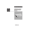
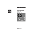
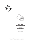
®
01215
MRD1400HZ16
Camera Control
Interface for the
CC1400HZ16
Installation/
Operation Manual
C1973M-B (8/03)
Pelco • 3500 Pelco Way • Clovis, CA 93612-5699 USA • www.pelco.com
In North America and Canada: Tel (800) 289-9100 • FAX (800) 289-9150
International Customers: Tel +1(559) 292-1981 • FAX +1(559) 348-1120
CONTENTS
Section
Page
IMPORTANT SAFEGUARDS AND WARNINGS ................................................................ 3
DESCRIPTION ................................................................................................................... 4
INSTALLATION .................................................................................................................. 4
DIP SWITCH SETTINGS ........................................................................................... 4
BAUD RATE SELECTION ................................................................................. 4
MRD ADDRESS SETTINGS .............................................................................. 5
MRD1400HZ16 INSTALLATION METHODS ............................................................. 6
WALL MOUNTING ............................................................................................. 6
DF5/DF8 SERIES DOME INSTALLATION ........................................................ 6
EH3512 SERIES ENCLOSURE INSTALLATION .............................................. 8
EH2512 SERIES ENCLOSURE INSTALLATION .............................................. 9
CONTROL, POWER, AND CAMERA CONNECTIONS ............................................ 10
OPERATION ..................................................................................................................... 11
TROUBLESHOOTING ...................................................................................................... 12
WARRANTY AND RETURN INFORMATION .................................................................... 12
LIST OF ILLUSTRATONS
Figure
1
2
3
4
5
6
7
8
9
10
Page
SW-1 Default Switch Settings ............................................................................ 4
Wall Mounting .................................................................................................... 6
DF5/DF8 Installation .......................................................................................... 7
Removing the MRD Board ................................................................................. 7
Installing the EH3512 Adapter ........................................................................... 8
Installing the MRD Board onto the EH3512 Adapter .......................................... 8
EH2512 Series Enclosure Installation ................................................................ 9
Control, Power, and Camera Connections ........................................................ 10
Multiple Units with Parallel Connections ........................................................... 10
Data Cable Wiring ............................................................................................. 10
LIST OF TABLES
Table
A
B
C
2
Page
Baud Rate Switch Settings ................................................................................ 4
MRD DIP Switch Settings .................................................................................. 5
Two-Wire Control Connections ......................................................................... 10
Pelco Manual C1973M-B (8/03)
IMPORTANT SAFEGUARDS AND WARNINGS
Prior to installation and use of this product, the following WARNINGS should be observed.
1.
Installation and servicing should only be done by qualified service personnel and conform to all local codes.
2.
There are no user-serviceable parts inside this unit. Only authorized service personnel
may open the unit.
3.
To reduce the risk of fire or electric shock, do not expose this unit to rain or moisture if
this unit is designed for indoor use only.
The product and/or manual may bear the following marks:
This symbol indicates that dangerous voltage constituting a risk of electric shock is
present within this unit.
This symbol indicates that there are important operating and maintenance instructions
in the literature accompanying this unit.
CAUTION:
RISK OF ELECTRIC SHOCK.
DO NOT OPEN.
Please thoroughly familiarize yourself with the information in this manual prior to installation
and operation.
Pelco Manual C1973M-B (8/03)
3
DESCRIPTION
The MRD1400HZ16 is a camera interface control for Pelco’s CC1400HZ16 Series digital
color camera. The unit can be mounted directly to a wall or installed in a DF5 Series dome,
DF8A Series dome, EH2512 Series enclosure, or EH3512 Series enclosure.
The MRD1400HZ16 can be used with the following Pelco controllers and matrix switchers:
Controllers (direct mode only)
MPT9500, CM9760-KBD Series, KBD200A,
and KBD300A
Matrix Switchers
(configured for D or P protocols only)
CM6700 Series, CM6800 Series, CM9740
Series, and CM9760 Series
INSTALLATION
The following items are supplied:
Qty.
1
1
1
1
1
4
1
1
Item
MRD1400HZ16
DF5/DF8/EH2512 Series adapter
EH3500 Series adapter
4-pin connector
Data cable (12 inches)
4-40 Phillips button head screws
#10 nut and washer
Camera sled for EH3500 Series enclosure
DIP SWITCH SETTINGS
NOTE: Baud/Address
Settings – If switch settings
are changed while the power
to the MRD unit is ON, push
and hold the reset button for
five seconds and then
release, to recycle power
and accept the new baud/
address setting. Refer to
Figure 4 for the location of
the reset button.
BAUD RATE SELECTION
The baud rate must be set for the MRD1400HZ16 to automatically sense D or P protocol.
The default communication rate for the MRD1400HZ16 is 4800 baud. If the system’s controller/switcher uses a different communication rate, change the baud rate of the
MRD1400HZ16 to match the controller/switcher.
To change the baud rate, refer to Figure 1 and Table A.
P
W
R
DATA
IN
Table A. Baud Rate Switch Settings
RST
DATA
CAM
SW1
MRD1400HZ16
Made in USA
NOTE: Dip switches 8, 9,
and 10 are factory set. Do
not change switch positions.
Baud
Rate
Switch Setting
6
7
2400
OFF
OFF
4800
ON
OFF
9600
OFF
ON
DEFAULT SWITCH
SETTINGS: 6 & 10 ON
ALL OTHER SWITCHES OFF
01218
Figure 1. SW-1 Default Switch Settings
4
Pelco Manual C1973M-B (8/03)
MRD ADDRESS SETTINGS
A camera address setting is required for the controller/switcher to communicate with the
MRD1400HZ16. The default setting for the MRD is Receiver Address 1. If you are using
more than one MRD, each unit must have a different Receiver Address.
To change the address setting of the MRD, refer to Figure 1 and Table B.
Table B. MRD DIP Switch Settings
Receiver
Address
Pelco Manual C1973M-B (8/03)
MRD DIP Switch Setting
1
2
3
4
5
1
Off
Off
Off
Off
Off
2
On
Off
Off
Off
Off
3
Off
On
Off
Off
Off
4
On
On
Off
Off
Off
5
Off
Off
On
Off
Off
6
On
Off
On
Off
Off
7
Off
On
On
Off
Off
8
On
On
On
Off
Off
9
Off
Off
Off
On
Off
10
On
Off
Off
On
Off
11
Off
On
Off
On
Off
12
On
On
Off
On
Off
13
Off
Off
On
On
Off
14
On
Off
On
On
Off
15
Off
On
On
On
Off
16
On
On
On
On
Off
17
Off
Off
Off
Off
On
18
On
Off
Off
Off
On
19
Off
On
Off
Off
On
20
On
On
Off
Off
On
21
Off
Off
On
Off
On
22
On
Off
On
Off
On
23
Off
On
On
Off
On
24
On
On
On
Off
On
25
Off
Off
Off
On
On
26
On
Off
Off
On
On
27
Off
On
Off
On
On
28
On
On
Off
On
On
29
Off
Off
On
On
On
30
On
Off
On
On
On
31
Off
On
On
On
On
32
On
On
On
On
On
5
MRD1400HZ16 INSTALLATION METHODS
There are three methods of installation for the MRD1400HZ16. The unit can be mounted
directly to a wall, or installed inside a dome or enclosure using the supplied mount adapters.
Refer to the following sections and select the correct installation method for your application.
WALL MOUNTING
To mount the MRD1400HZ16 directly to a wall, refer to Figure 2 and do the following:
1.
Select the mounting location. Install the unit close to the camera.
2.
Use the MRD1400HZ16 as a template to mark the two fastener positions onto the
mounting surface.
3.
Prepare the surface and install the fasteners. Do not tighten fasteners at this time.
4.
Align the mounting holes of the MRD1400HZ16 with the installed wall fasteners.
5.
Place the unit over the fasteners, and then slide the box down into position. Tighten
the fasteners to secure the unit to the wall.
6.
Make all required control, power, and camera connections. Refer to Figure 8 and the
Use only UL listed
Class 2 Power Source
Control, Power, and Camera Connections section of this manual.
4-40 PHILLIPS BUTTON
HEAD SCREW
TO
CAMERA
01220
Figure 2. Wall Mounting
DF5/DF8 SERIES DOME INSTALLATION
To install the MRD1400HZ16 in a DF5/DF8 dome:
1.
Remove the MRD board from the MRD1400HZ16. To remove the board:
a.
Unscrew the two Phillips button head screws from the unit (refer to Figure 2), and
remove the cover. Discard the screws.
b.
Using a small screwdriver, carefully pry each corner of the board from the PEM
studs. Refer to Figure 4.
2.
Use the four 4-40 Phillips button head screws (provided) to attach the board to the
DF5/DF8/EH2512 Series adapter.
3.
Assemble the tilt table supplied with the dome. For detailed instructions refer to the
manual supplied with the DF5/DF8 Series dome.
4.
Refer to Figure 3. Attach the board to the tilt table with the supplied #10 nut and
washer.
5.
Make all required control, power, and camera connections. Refer to Figure 8 and the
Control, Power, and Camera Connections section of this manual.
6.
6
Refer to the manual supplied with the DF5 or DF8 Series dome to install the camera
and complete the installation.
Pelco Manual C1973M-B (8/03)
CAMERA BRACKET
DOME
MRD1400HZ16
AND MOUNT ADAPTER
01212
Figure 3. DF5/DF8 Installation
POWER LED
RESET BUTTON
DATA LED
01216
Figure 4. Removing the MRD Board
Pelco Manual C1973M-B (8/03)
7
EH3512 SERIES ENCLOSURE INSTALLATION
Do the following to install the MRD1400HZ16 in an EH3512 Series enclosure:
1.
Remove the camera sled from the EH3512 Series enclosure. If the camera is attached
to the sled remove the camera.
2.
Attach the camera to the 4-inch camera sled supplied with the MRD. Install the camera sled and camera into the enclosure. Place the camera sled as close to the viewing
window as possible.
3.
Remove the PC board from the MRD1400HZ16. To remove the board:
a.
Unscrew the two Phillips button head screws from the unit (refer to Figure 2), and
remove the cover.
b.
Using a small screwdriver, carefully pry each corner of the board from the PEM
studs. Refer to Figure 4.
4.
Refer to Figure 5. Install the EH3512 adapter into the enclosure.
5.
Make all required control, power, and camera connections to the board. Refer to
Figure 8 and the Control, Power and Camera Connections section of this manual.
6.
Refer to Figure 6. Position the board over the EH3512 adapter. The DIP switches of
the board should face up. Lightly press on each corner of the board to attach it to the
PEM studs of the adapter.
BACK OF
EH3512
ADAPTER PLATE
01213
Figure 5. Installing the EH3512 Adapter
PEM
STUD
MRD-1400HZ16
DIP SWITCHES
01214
Figure 6. Installing the MRD Board onto the EH3512 Adapter
8
Pelco Manual C1973M-B (8/03)
EH2512 SERIES ENCLOSURE INSTALLATION
To install the MRD1400HZ16 in an EH2512 Series enclosure:
1.
Remove the PC board from the MRD1400HZ16. To remove the board:
a.
Unscrew the two Phillips button head screws from the unit (refer to Figure 2), and
remove the cover. Discard the screws.
b.
Using a small screwdriver, carefully pry each corner of the board from the PEM
studs. Refer to Figure 4.
2.
Use the four 4-40 Phillips button head screws (provided) to attach the board to the
DF5/DF8/EH2512 Series adapter.
3.
Remove the camera sled from the housing. Refer to the manual supplied with the
EH2512 Series enclosure.
4.
Make all required control, power, and camera connections. Refer to Figure 8 and the
Control, Power, and Camera Connections section of this manual.
5.
Refer to Figure 7. Attach the board to the camera sled of the enclosure with the supplied #10 nut and washer.
6.
Refer to the manual supplied with the EH2512 Series enclosure to install the camera
and complete the installation.
MRD BOARD
DATA IN
CONNECTION
#10 WASHER
#10 NUT
01217
Figure 7. EH2512 Series Enclosure Installation
Pelco Manual C1973M-B (8/03)
9
CONTROL, POWER, AND CAMERA CONNECTIONS
1.
Refer to Figure 8 and Table C. Connect the control wires from the controller to the
MRD DATA IN connector. Use the supplied four-pin connector. To connect multiple
units with parallel connections refer to Figure 9.
2.
Connect one end of the 12-inch data cable into the CAM input of the MRD (refer to
Figure 8). Connect the other end of the cable to the camera connector labeled CONTROL OUT. If the installation requires a longer data cable refer to Figure 10. Maximum
cable length is 25-feet.
3.
Make required power connections. Refer to Figure 8.
Note: Input power range 12-24 volts AC/DC.
T+
TRR+
(+)
NO CONNECT
(-)
Table C. Two-Wire Control Connections
From
Controller
MRD
TX+
R+
TX-
R-
P
W
R
DATA
IN
RST
DATA
CAM
SW1
MRD1400HZ16
Made in USA
01219
Figure 8. Control, Power, and Camera Connections
CC1400HZ16
CC1400HZ16
CC1400HZ16
FROM THE
CONTROLLER
Tx+
Tx-
MRD
MRD
MRD
T+ T- R+ R-
T+ T- R+ R-
T+ T- R+ R-
Figure 9. Multiple Units with Parallel Connections
PIN
1
2
3
4
5
6
7
8
ONE TWIST IN CABLE
PIN
8
7
6
5
4
3
2
1
LOCKING TAB ON BOTTOM
Figure 10. Data Cable Wiring
10
01221
Pelco Manual C1973M-B (8/03)
OPERATION
CAMERA OPERATION
PELCO CONTROLLER COMMAND
Zoom In
Tilt joystick up
Zoom Out
Tilt joystick down
Quickly Zoom In
Press the Zoom Tele button or turn the joystick clockwise
Quickly Zoom Out
Press the Zoom Wide button or turn the joystick counterclockwise
Focus Near
Press the Focus Near button
Focus Far
Press the Focus Far button
Increase Brightness
Press the Iris Open button
Decrease Brightness
Press the Iris Close button
Enter/Exit the camera menu
*Preset 95 or AUX 8 ON
Navigate through the camera menu
Move the joystick up or down to move through menu selections
Increase the value of the selected menu item
Press the Focus Far button
Decrease the value of the selected menu item
Press the Focus Near button
PRESETS (Refer to the documentation supplied with the controller for instructions on how to set and call a preset.)
Save camera action as preset 1-8
1-8 Set
Move to preset position 1-8
1-8 Call
Clear control lockup if undefined preset is called
Preset 9 Call
Enter/Exit menu
*Preset 95 Call
AUX (Refer to the documentation supplied with the controller for instructions on auxiliary commands.)
Turn camera power on
Aux 1 on
Turn camera power off
Aux 1 off
Enable/Disable the three digit MRD address display
Aux 2 on
Turn digital zoom on
Aux 3 on
Turn digital zoom off
Aux 3 off
Reset the Camera
Aux 4 on
Display mirror image on screen; left-right flip
(digital zoom must be enabled)
Aux 6 on
Display normal image on screen
(digital zoom must be enabled)
Aux 6 off
Display current software version for 3 seconds
Aux 7 on
Enter/Exit menu
*Aux 8 on
*Subsequent operation must be performed before repeating command.
Pelco Manual C1973M-B (8/03)
11
TROUBLESHOOTING
Problem
Possible Cause and Solutions
Unit does not operate. No power.
1. Check to see if the power LED is lit. If the LED is not lit:
a. Verify input power is good.
b. Check power connections to make sure the wires are making contact.
c. Verify the input power source is in range 12-24 volts AC/DC.
Camera does not respond or
responds improperly to commands.
1. Check the baud rate of the MRD and the controller/switcher. Both should have the
same baud rate setting.
2. The camera address is not set correctly. Check the MRD camera address setting.
3. If the baud or address switch settings are changed, press the power reset button (see
Figure 4).
Video erratic. Control lock up.
Can not call preset.
1. The selected preset has not been defined. To clear lock up:
a. Call preset 9.
b. Define new preset.
DATA LED is not lit.
1. Check connection to the camera.
2. Push and hold the power reset button for 5 seconds and then release, to recycle power
to the camera. Refer to Figure 4.
SPECIFICATIONS
MECHANICAL
Construction:
Dimensions:
Electrical:
Power Consumption:
Communication:
Aluminum
3.30 (H) x 3.70 (W) x 1.12 (D) inches (8.38 x 9.40 x 2.84 cm)
12-24 VAC/VDC (+10%/-15%), 50/60-HZ
<1 watt
RS-422, half-duplex
(Design and product specifications subject to change without notice.)
PRODUCT WARRANTY AND RETURN INFORMATION
WARRANTY
Pelco will repair or replace, without charge, any merchandise proved defective in material or
workmanship for a period of one year after the date of shipment.
Exceptions to this warranty are as noted below:
• Five years on FT/FR8000 Series fiber optic products.
• Three years on Genex ® Series products (multiplexers, server, and keyboard).
• Three years on Camclosure ® and fixed camera models, except the CC3701H-2,
CC3701H-2X, CC3751H-2, CC3651H-2X, MC3651H-2, and MC3651H-2X camera models,
which have a five-year warranty.
• Two years on standard motorized or fixed focal length lenses.
• Two years on Legacy ®, CM6700/CM6800/CM9700 Series matrix, and DF5/DF8 Series
fixed dome products.
• Two years on Spectra ®, Esprit®, ExSite™, and PS20 scanners, including when used in
continuous motion applications.
• Two years on Esprit ® and WW5700 Series window wiper (excluding wiper blades).
• Eighteen months on DX Series digital video recorders, NVR300 Series network video
recorders, and Endura ™ Series distributed network-based video products.
• One year (except video heads) on video cassette recorders (VCRs). Video heads will be
covered for a period of six months.
• Six months on all pan and tilts, scanners or preset lenses used in continuous motion
applications (that is, preset scan, tour and auto scan modes).
Pelco will warrant all replacement parts and repairs for 90 days from the date of Pelco
shipment. All goods requiring warranty repair shall be sent freight prepaid to Pelco, Clovis,
California. Repairs made necessary by reason of misuse, alteration, normal wear, or accident
are not covered under this warranty.
Pelco assumes no risk and shall be subject to no liability for damages or loss resulting from
the specific use or application made of the Products. Pelco’s liability for any claim, whether
based on breach of contract, negligence, infringement of any rights of any party or product
liability, relating to the Products shall not exceed the price paid by the Dealer to Pelco for
such Products. In no event will Pelco be liable for any special, incidental or consequential
damages (including loss of use, loss of profit and claims of third parties) however caused,
whether by the negligence of Pelco or otherwise.
The above warranty provides the Dealer with specific legal rights. The Dealer may also have
additional rights, which are subject to variation from state to state.
If a warranty repair is required, the Dealer must contact Pelco at (800) 289-9100 or
(559) 292-1981 to obtain a Repair Authorization number (RA), and provide the following
information:
1. Model and serial number
2. Date of shipment, P.O. number, Sales Order number, or Pelco invoice number
3. Details of the defect or problem
If there is a dispute regarding the warranty of a product which does not fall under the
warranty conditions stated above, please include a written explanation with the product
when returned.
Method of return shipment shall be the same or equal to the method by which the item was
received by Pelco.
RETURNS
In order to expedite parts returned to the factory for repair or credit, please call the factory at
(800) 289-9100 or (559) 292-1981 to obtain an authorization number (CA number if returned
for credit, and RA number if returned for repair).
All merchandise returned for credit may be subject to a 20% restocking and refurbishing
charge.
Goods returned for repair or credit should be clearly identified with the assigned CA or RA
number and freight should be prepaid. Ship to the appropriate address below.
If you are located within the continental U.S., Alaska, Hawaii or Puerto Rico, send goods to:
Service Department
Pelco
3500 Pelco Way
Clovis, CA 93612-5699
If you are located outside the continental U.S., Alaska, Hawaii or Puerto Rico and are
instructed to return goods to the USA, you may do one of the following:
If the goods are to be sent by a COURIER SERVICE, send the goods to:
Pelco
3500 Pelco Way
Clovis, CA 93612-5699 USA
If the goods are to be sent by a FREIGHT FORWARDER, send the goods to:
Pelco c/o Expeditors
473 Eccles Avenue
South San Francisco, CA 94080 USA
Phone: 650-737-1700
Fax: 650-737-0933
REVISION HISTORY
Manual #
C1973M
C1973M-A
C1973M-B
Date
10/01
8/02
8/03
Comments
Original version.
Revised instructions.
Revised supplied parts list and installation instructions for DF5/DF8 and EH2512 enclosures.
Pelco, the Pelco logo, Camclosure, Esprit, Genex, Legacy, and Spectra are registered trademarks of Pelco.
Endura and ExSite are trademarks of Pelco.
12
© Copyright 2003, Pelco
All rights reserved.
Pelco Manual C1973M-B (8/03)