1
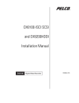
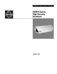
I N S T A L L A T I O N
FT8301A Miniature
Fiber Transmitter
Single-Channel Digitally Encoded Video
C1680M (1/06)
Contents
Important Safety Instructions . . . . . . . . . . . . . . . . . . . . . . . . . . . . . . . . . . . . . . . . . . . . . . 4
Regulatory Notices . . . . . . . . . . . . . . . . . . . . . . . . . . . . . . . . . . . . . . . . . . . . . . . . . . . . . . 6
Product Overview . . . . . . . . . . . . . . . . . . . . . . . . . . . . . . . . . . . . . . . . . . . . . . . . . . . . . . . .
Description . . . . . . . . . . . . . . . . . . . . . . . . . . . . . . . . . . . . . . . . . . . . . . . . . . . . . . . .
Models . . . . . . . . . . . . . . . . . . . . . . . . . . . . . . . . . . . . . . . . . . . . . . . . . . . . . . . . . . .
Front Panel . . . . . . . . . . . . . . . . . . . . . . . . . . . . . . . . . . . . . . . . . . . . . . . . . . . . . . . .
Installation . . . . . . . . . . . . . . . . . . . . . . . . . . . . . . . . . . . . . . . . . . . . . . . . . . . . . . . . . . . .
Package Contents . . . . . . . . . . . . . . . . . . . . . . . . . . . . . . . . . . . . . . . . . . . . . . . . . .
Connections . . . . . . . . . . . . . . . . . . . . . . . . . . . . . . . . . . . . . . . . . . . . . . . . . . . . . .
Mounting . . . . . . . . . . . . . . . . . . . . . . . . . . . . . . . . . . . . . . . . . . . . . . . . . . . . . . . . .
Mounting the Transmitter to a Wall . . . . . . . . . . . . . . . . . . . . . . . . . . . . . . .
Mounting the Transmitter into an EH2515 Series Enclosure . . . . . . . . . . . .
Mounting the Transmitter into an EH3512/EH3515 Series Enclosure . . . . .
Mounting the Transmitter into a DF5/DF8 Dome . . . . . . . . . . . . . . . . . . . . .
7
7
7
9
10
10
11
13
13
14
18
24
Troubleshooting . . . . . . . . . . . . . . . . . . . . . . . . . . . . . . . . . . . . . . . . . . . . . . . . . . . . . . . . 31
Specifications . . . . . . . . . . . . . . . . . . . . . . . . . . . . . . . . . . . . . . . . . . . . . . . . . . . . . . . . . 32
List of Illustrations
1
2
3
4
5
6
7
8
9
10
11
12
13
14
15
16
17
18
19
Single-Channel Video Transmission Using FT8301A Transmitter . . . . . . . . . . . . . 8
Front Panel of FT8301A Transmitter—Multimode and Single-Mode Models. . . 9
FT8301A Transmitter Connections. . . . . . . . . . . . . . . . . . . . . . . . . . . . . . . . . . . . 12
Mounting FT8301A Transmitter to a Wall (Top View of Transmitter) . . . . . . . . . 13
Attaching EH2500 Bracket to FT8301A Transmitter . . . . . . . . . . . . . . . . . . . . . . 15
Mounting FT8301A Transmitter into EH2515 Enclosure . . . . . . . . . . . . . . . . . . . 16
Routing Fiber Optic Cable in EH2515 Enclosure . . . . . . . . . . . . . . . . . . . . . . . . . 17
Attaching EH3500 Brackets to FT8301A Transmitter . . . . . . . . . . . . . . . . . . . . . 18
Attaching Replacement Gland and Plug to EH3512/EH3515 Enclosure. . . . . . . 19
Removing EH3512/EH3515 Enclosure Accessories . . . . . . . . . . . . . . . . . . . . . . 20
Mounting FT8301A Transmitter into EH3512/EH3515 Enclosure . . . . . . . . . . . . 21
Routing Fiber Optic Cable in EH3512/EH3515 Enclosure . . . . . . . . . . . . . . . . . . 22
Reinstalling EH3512/EH3515 Heater Bracket, Blower, and Heater . . . . . . . . . . 23
Reinstalling EH3512/EH3515 PC Board . . . . . . . . . . . . . . . . . . . . . . . . . . . . . . . 23
Attaching DF5/DF8 Bracket to FT8301A Transmitter . . . . . . . . . . . . . . . . . . . . . 24
Removing Tilt Bracket from DF5/DF8 In-Ceiling Dome . . . . . . . . . . . . . . . . . . . . 25
Mounting FT8301A Transmitter into DF5/DF8 In-Ceiling Dome . . . . . . . . . . . . . 26
Removing Tilt Bracket from DF5/DF8 Pendant Dome . . . . . . . . . . . . . . . . . . . . . 28
Mounting FT8301A Transmitter into DF5/DF8 Pendant Dome . . . . . . . . . . . . . . 29
List of Tables
A
C1680M (1/06)
Troubleshooting with Front-Panel Indicators . . . . . . . . . . . . . . . . . . . . . . . . . . . 31
3
Important Safety Instructions
1. Read these instructions.
2. Keep these instructions.
3. Heed all warnings.
4. Follow all instructions.
5. Do not use this apparatus near water.
6. Clean only with dry cloth.
7. Do not block any ventilation openings. Install in accordance with the manufacturer’s
instructions.
8. Do not install near any heat sources such as radiators, heat registers, stoves, or other
apparatus (including amplifiers) that produce heat.
9. Do not defeat the safety purpose of the polarized or grounding-type plug. A polarized plug has
two blades with one wider than the other. A grounding type plug has two blades and a third
grounding prong. The wide blade or the third prong are provided for your safety. If the provided
plug does not fit into your outlet consult an electrician for replacement of the obsolete outlet.
10. Protect the power cord from being walked on or pinched particularly at plugs, convenience
receptacles, and the points where they exit from the apparatus.
11. Only use attachments/accessories specified by the manufacturer.
12. Use only with the cart, stand, tripod, bracket, or table specified by the manufacturer, or sold
with the apparatus. When a cart is used, use caution when moving the cart/apparatus
combination to avoid injury from tip-over.
13. Refer all servicing to qualified service personnel. Servicing is required when the apparatus has
been damaged in any way, such as power-supply cord or plug is damaged, liquid has been
spilled or objects have fallen into the apparatus, the apparatus has been exposed to rain or
moisture, does not operate normally, or has been dropped.
14. Apparatus shall not be exposed to dripping or splashing and that no objects filled with liquids,
such as vases shall be placed on the apparatus.
15. WARNING: To reduce the risk of fire or electric shock, do not expose this apparatus to rain or
moisture.
16. Installation should be done only by qualified personnel and conform to all local codes.
17. Unless the unit is specifically marked as a NEMA Type 3, 3R, 3S, 4, 4X, 6, or 6P enclosure, it is
designed for indoor use only and it must not be installed where exposed to rain and moisture.
18. Use only installation methods and materials capable of supporting four times the maximum
specified load.
19. A CCC-approved power cord must be used to power this equipment when used in China.
20. CAUTION: These servicing instructions are for use by qualified service personnel only. To
reduce the risk of electric shock do not perform any servicing other than that contained in the
operating instructions unless you are qualified to do so.
4
C1680M (1/06)
The product and/or manual may bear the following marks:
This symbol indicates that dangerous voltage
constituting a risk of electric shock is present
within this unit.
This symbol indicates that there are important
operating and maintenance instructions in the
literature accompanying this unit.
C1680M (1/06)
CAUTION:
RISK OF ELECTRIC SHOCK.
DO NOT OPEN.
5
Regulatory Notices
This device complies with Part 15 of the FCC Rules. Operation is subject to the following two
conditions: (1) this device may not cause harmful interference, and (2) this device must accept any
interference received, including interference that may cause undesired operation.
RADIO AND TELEVISION INTERFERENCE
This equipment has been tested and found to comply with the limits of a Class A digital device,
pursuant to Part 15 of the FCC Rules. These limits are designed to provide reasonable protection
against harmful interference when the equipment is operated in a commercial environment. This
equipment generates, uses, and can radiate radio frequency energy and, if not installed and used in
accordance with the instruction manual, may cause harmful interference to radio communications.
Operation of this equipment in a residential area is likely to cause harmful interference in which case
the user will be required to correct the interference at his own expense.
Changes and Modifications not expressly approved by the manufacturer or registrant of this
equipment can void your authority to operate this equipment under Federal Communications
Commission’s rules.
This Class A digital apparatus complies with Canadian ICES-003.
Cet appareil numérique de la classe A est conforme à la norme NMB-003 du Canada.
6
C1680M (1/06)
Product Overview
DESCRIPTION
The FT8301A miniature fiber transmitter provides the ability to transmit one composite video channel
over one optical fiber. The FT8301A transmitter is compatible with the single-channel FR8301A and
dual-channel FR8302A receivers. In addition, the FT8301A transmitter is backward compatible with
the single-channel FR8301 receiver.
Specially designed for use in Pelco® EH2515/EH3512/EH3515 Series camera enclosures and DF5/DF8
Series fixed mount domes, the FT8301A transmitter can also be used as a standalone module (refer
to Figure 1).
Features of the FT8301A transmitter include the following:
•
8-bit digitally encoded video for high-quality video transmission over a single fiber
•
Multimode fiber support for distances up to 6 km (3.7 mi)
•
Single-mode fiber support for distances up to 46 km (28.6 mi)
•
Exceeds all requirements for the RS-250C Medium-Haul Transmission specification
•
Compatible with NTSC, PAL, and SECAM video standards
•
Designed to meet NEMA TS 2 and Caltrans traffic signal control equipment standards for
ambient operating temperature, mechanical shock and vibration, humidity with condensation,
high-line/low-line voltage conditions, and transient voltage protection
NOTE: Conformal coating is required for operation in environments with relative humidity
above 95% (condensing).
•
No performance adjustments required
•
12 VDC or 24 VAC power supply
•
LED indicators for monitoring of signal status and laser status
The FT8301A transmitter is a Class 1 laser product that complies with FDA radiation performance
standard 21CFR Subchapter J and with IEC 60825-1 Edition 1.2, 2001-08.
MODELS
The FT8301A transmitter consists of the following series of models:
Multimode Models:*
FT8301AMST
Single-channel fiber optic video transmitter; multimode, ST connector;
transmission distance up to 2 km
FT8301AMSTE
Single-channel fiber optic video transmitter; multimode, ST connector;
transmission distance up to 6 km (extended distance)
Single-Mode Models:*
FT8301ASST
Single-channel fiber optic video transmitter; single-mode, ST connector
FT8301ASFC
Single-channel fiber optic video transmitter; single-mode, FC connector
*For conformal coated models, replace the first letter F in the model number with the letter C. The
conformal coated version of FT8301AMST, for example, is CT8301AMST.
C1680M (1/06)
7
FT8301A
TRANSMITTER
ONE
FIBER
COMPATIBLE
RECEIVER
ONE
VIDEO
OUTPUT
EH2515
ENCLOSURE
FT8301A
TRANSMITTER
EH3512/EH3515
ENCLOSURE
ONE
FIBER
ONE
FIBER
COMPATIBLE
RECEIVER
COMPATIBLE
RECEIVER
ONE
VIDEO
OUTPUT
ONE
VIDEO
OUTPUT
FT8301A
TRANSMITTER
DF5/DF8
FIXED MOUNT DOME
ONE
VIDEO
INPUT
FT8301A
TRANSMITTER
ONE
FIBER
COMPATIBLE
RECEIVER
ONE
VIDEO
OUTPUT
STANDALONE
MODULE
Figure 1. Single-Channel Video Transmission Using FT8301A Transmitter
8
C1680M (1/06)
FRONT PANEL
The front panel of the FT8301A transmitter provides connectors and LED indicators (refer to Figure 2).
�
MULTIMODE
MODELS
� � � ��
�
SINGLE-MODE
MODELS
� � �
�
�
Figure 2. Front Panel of FT8301A Transmitter—Multimode and Single-Mode Models
� POWER CONNECTOR, 2-pin connector; removable mating connector with screw terminals (not
shown)
� VIDEO IN UTP (UNSHIELDED TWISTED PAIR) CONNECTOR, 100-ohm differential analog video
input; 2-pin connector; removable mating connector with spring-cage terminals (not shown)
� VIDEO IN BNC CONNECTOR, 75-ohm analog video input
� OPTIC FAULT LED, laser status indicator
� VIDEO PRESENT LED, video signal status indicator
� FIBER OPTIC CONNECTOR, ST (multimode and single-mode models) or FC (single-mode models
only)
NOTE: The FT8301A transmitter provides two video input connectors: one UTP connector and one
BNC connector. Only one of the connectors can be used at one time.
For additional information about front-panel connections, refer to the Installation section. For
additional information about the front-panel indicators, refer to the Troubleshooting section.
C1680M (1/06)
9
Installation
PACKAGE CONTENTS
The following items are supplied:
1
FT8301A transmitter with attached left and right wall-mounting brackets
1
Regulated switching power supply with four plug adapters (North American, Australian, U.K.,
and European configurations); 100-240 VAC, 50-60 Hz input, 12 VDC output
1
BNC-to-BNC RG179/U coaxial cable
1
EH2500 Series accessory kit, which contains the following:
1
2
1
EH2500 bracket
4-40 x 0.187-inch Phillips flat head screws
10-32 x 0.375-inch Phillips pan head screw and lock washer
The EH2500 Series accessory kit must be used when installing the FT8301A transmitter into an
EH2515 Series enclosure.
1
EH3500 Series accessory kit, which contains the following:
2
4
1
1
EH3500 brackets (one left, one right)
4-40 x 0.25-inch Phillips pan head screws and lock washers
Replacement gland
Rubber plug
The EH3500 Series accessory kit must be used when installing the FT8301A transmitter into an
EH3512/EH3515 Series enclosure.
1
DF5/DF8 Series accessory kit, which contains the following:
1
4
DF5/DF8 bracket
4-40 x 0.187-inch Phillips flat head screws
The DF5/DF8 Series accessory kit must be used when installing the FT8301A transmitter into a
DF5/DF8 fixed mount dome.
1
10
FT8301A Miniature Fiber Transmitter Installation manual (this manual)
C1680M (1/06)
CONNECTIONS
Before mounting the FT8301A transmitter, note the following transmitter connections (refer to
Figure 3):
•
Power connection
NOTES:
–
A 12 VDC or 24 VAC power supply can be used to power the transmitter. A 12 VDC
power supply is provided. If a 24 VAC power supply is used, the power supply must be a
Listed Direct Plug-In Power Unit marked as Class 2 and rated as 24 VAC, 200 mA
(minimum output).
–
In extreme temperature conditions, it is recommended that an industrial-rated outdoor
power supply such as the Pelco WCS1-4 power supply be used.
•
Fiber connection
•
Video input connection (UTP or BNC per channel)
NOTE: When connecting to the UTP connector, it is recommended that solid UTP wire rather
than stranded UTP wire be used. If stranded UTP wire is used, it is recommended that you tin
the stranded wire.
C1680M (1/06)
11
MULTIMODE
MODELS
OR
UTP
WIRES
POWER
CONNECTION
COAXIAL
CABLE
FIBER OPTIC
CABLE
SINGLE-MODE
MODELS
OR
UTP
WIRES
POWER
CONNECTION
COAXIAL
CABLE
FIBER OPTIC
CABLE
Figure 3. FT8301A Transmitter Connections
12
C1680M (1/06)
MOUNTING
This section provides information about the following:
•
Mounting the transmitter to a wall
•
Mounting the transmitter into an EH2515 Series enclosure
•
Mounting the transmitter into an EH3512/EH3515 Series enclosure
•
Mounting the transmitter into a DF5/DF8 fixed mount dome
Note that the transmitter can also be placed on a desktop.
MOUNTING THE TRANSMITTER TO A WALL
NOTE: Before mounting the transmitter to a wall, ensure that the positioning of the unit allows
viewing of the LEDs and provides space for making the various cable connections.
The transmitter is shipped with attached left and right wall-mounting brackets. To mount the
transmitter to a wall, attach the unit with two screws (not provided) using the wall-mounting keyholes
(refer to Figure 4).
WALL-MOUNTING
KEYHOLE
WALL-MOUNTING
KEYHOLE
Figure 4. Mounting FT8301A Transmitter to a Wall (Top View of Transmitter)
C1680M (1/06)
13
MOUNTING THE TRANSMITTER INTO AN EH2515 SERIES
ENCLOSURE
The following procedure provides instructions to mount the FT8301A transmitter into an existing
EH2515 Series enclosure installation.
To mount the transmitter into an EH2515 Series enclosure, do the following:
1. Using a small Phillips screwdriver, remove the left and right wall-mounting brackets that are
attached to the transmitter by loosening the four 4-40 x 0.25-inch Phillips pan head screws
(two screws each side).
2. Using the EH2500 bracket and the two 4-40 x 0.187-inch Phillips flat head screws supplied in
the EH2500 accessory kit, attach the bracket to the transmitter (refer to Figure 5). Note that
the transmitter must be positioned at an angle within the bracket.
3. Disconnect power to the enclosure.
4. Remove the camera sled from the enclosure by doing the following:
a.
Using a 5/64-inch hex wrench, loosen the screws on the back of the enclosure.
b.
Pull the “T” handle until heater wiring connectors, if present, are visible, and then
disconnect the heater wiring connectors.
WARNING: Damage to the heater wires can occur if the sled is pulled out too far
before the wiring connectors are separated.
c.
Slide the camera sled out of the enclosure.
5. Disconnect power wires and video cable from the connectors on the camera.
6. Mount the EH2500 bracket and attached transmitter into the enclosure by doing the following
(refer to Figure 6):
14
a.
Position the EH2500 bracket onto the camera sled so that the connectors on the
transmitter face the camera.
b.
Attach the EH2500 bracket to the camera sled using the 10-32 x 0.375-inch Phillips pan
head screw and lock washer supplied in the EH2500 accessory kit.
C1680M (1/06)
(2) SCREWS,
4-40 X 0.187-INCH,
PHILLIPS, FLAT HEAD
EH2500
BRACKET
SIDE VIEW OF EH2500
BRACKET WITH ATTACHED
FT8301A TRANSMITTER
Figure 5. Attaching EH2500 Bracket to FT8301A Transmitter
C1680M (1/06)
15
EH2500 BRACKET
WITH ATTACHED
FT8301A TRANSMITTER
LOCK WASHER, #10
SCREW, 10-32 X 0.375-INCH,
PHILLIPS, PAN HEAD
EH2515
ENCLOSURE
FT8301A TRANSMITTER
SIDE VIEW OF EH2515 ENCLOSURE
WITH FT8301A TRANSMITTER INSTALLED
Figure 6. Mounting FT8301A Transmitter into EH2515 Enclosure
16
C1680M (1/06)
7. Connect power, fiber optic, and video cables to the transmitter by doing the following:
a.
Insert the power cable through either of the two gland connectors on the enclosure,
route the cable underneath the transmitter toward the power connector on the
transmitter, and then connect the cable to the power connector.
b.
Insert the fiber optic cable through either of the two gland connectors on the enclosure,
and then do the following:
WARNING: When routing the fiber optic cable, be careful not to bend the fiber
at a sharp angle. Doing so breaks the fiber.
c.
(1)
Route the cable above the transmitter and then along one side of the camera until
you can loop the cable underneath the lens; then route the cable back along the
other side of the camera toward the fiber optic connector on the transmitter (refer
to Figure 7).
(2)
Connect the cable to the fiber optic connector on the transmitter.
Using the coaxial cable supplied with the transmitter, connect the cable to the BNC
connector on the transmitter and on the camera.
NOTE: For additional information about connections to the transmitter, refer to the Connections
section.
8. Reconnect power to the camera.
9. If applicable, reconnect the heater wires of the enclosure.
10. Carefully slide the camera sled back into the enclosure.
11. Reinstall the screws in the rear plate.
12. Reconnect power to the enclosure.
FIBER OPTIC CABLE
Figure 7. Routing Fiber Optic Cable in EH2515 Enclosure
C1680M (1/06)
17
MOUNTING THE TRANSMITTER INTO AN EH3512/EH3515 SERIES
ENCLOSURE
The following procedure provides instructions to mount the FT8301A transmitter into an existing
EH3512/EH3515 Series enclosure installation.
To mount the transmitter into an EH3512/EH3515 Series enclosure, do the following:
1. Using a small Phillips screwdriver, remove the left and right wall-mounting brackets that are
attached to the transmitter by loosening the four 4-40 x 0.25-inch Phillips pan head screws
(two screws each side).
2. Using the left- and right-mounting EH3500 brackets and the four 4-40 x 0.25-inch Phillips pan
head screws and lock washers supplied in the EH3500 Series accessory kit, attach the
brackets to the transmitter (refer to Figure 8). Note that the left- and right-mounting brackets
are marked L and R, respectively, to indicate the side of the transmitter to which each bracket
should be mounted.
R
(4) SCREWS, 4-40 X 0.25-INCH,
PHILLIPS, PAN HEAD WITH LOCK WASHER
Figure 8. Attaching EH3500 Brackets to FT8301A Transmitter
3. Disconnect power to the enclosure.
4. Unlatch and open the lid of the enclosure.
5. Disconnect power and video cables from the connectors on the camera.
If the enclosure is wired with conduit, skips steps 6-8 below and proceed to step 9. If the
enclosure is wired without conduit, proceed to step 6.
6. Pull the power and video cables out of the two glands at the bottom rear of the enclosure.
7. Remove the two glands at the bottom rear of the enclosure.
18
C1680M (1/06)
8. Do the following (refer to Figure 9):
a.
Using the replacement gland supplied in the EH3500 Series accessory kit, attach the
gland to either of the cable entry holes on the enclosure. Note that the replacement
gland is shorter than the two glands provided for the enclosure.
b.
Using the rubber plug supplied in the EH3500 Series accessory kit, attach the plug to the
remaining cable entry hole in the enclosure.
GLAND NUT
PLUG
REPLACEMENT
GLAND
Figure 9. Attaching Replacement Gland and Plug to EH3512/EH3515 Enclosure
9. If the enclosure contains the following accessory items, remove them from the enclosure
(refer to Figure 10):
a.
Remove the heater, blower, and rear heater bracket by loosening the two 6-32 x 1.5-inch
Phillips pan head screws and lock washers.
b.
Remove the PC board cover, cover bracket, PC board, and the associated four nylon
washers by loosening the two self-tapping screws. Note that you can discard the selftapping screws.
C1680M (1/06)
19
REAR HEATER BRACKET
BLOWER
HEATER
(2) SCREWS, 6-32 X 1.5-INCH,
PHILLIPS, PAN HEAD
WITH LOCK WASHER
SELF-TAPPING SCREW*
PC BOARD COVER
SELF-TAPPING SCREW*
COVER BRACKET
PC BOARD
(4) NYLON WASHERS
* DISCARD SELF-TAPPING SCREWS.
Figure 10. Removing EH3512/EH3515 Enclosure Accessories
10. Mount the transmitter into the enclosure by doing the following (refer to Figure 11):
20
a.
Position the transmitter at the rear of the enclosure with the connectors facing the
camera.
b.
Attach the transmitter to the enclosure by tightening the 6-32 captive screw on the leftand right-mounting EH3500 brackets.
C1680M (1/06)
6-32 CAPTIVE SCREW
(ONE SCREW EACH SIDE)
R
FT8301A
TRANSMITTER
SIDE VIEW OF EH3512/EH3515 ENCLOSURE
WITH FT8301A TRANSMITTER INSTALLED
Figure 11. Mounting FT8301A Transmitter into EH3512/EH3515 Enclosure
C1680M (1/06)
21
11. Connect power, fiber optic, and video cabling to the transmitter by doing the following:
a.
Insert the power cable through the gland or conduit on the bottom of the enclosure, and
then connect the cable to the power connector on the transmitter.
b.
Insert the fiber optic cable through the gland or conduit on the bottom of the enclosure,
and then do the following:
WARNING: When routing the fiber optic cable, be careful not to bend the fiber
at a sharp angle. Doing so breaks the fiber.
c.
(1)
Carefully loop the cable around the camera (refer to Figure 12).
(2)
Connect the cable to the fiber optic connector on the transmitter.
Using the coaxial cable supplied with the transmitter, connect the cable to the BNC
connector on the transmitter and on the camera.
NOTE: For additional information about connections to the transmitter, refer to the Connections
section.
FIBER OPTIC CABLE
Figure 12. Routing Fiber Optic Cable in EH3512/EH3515 Enclosure
12. Reinstall the enclosure accessories as follows:
a.
Reattach the rear heater bracket, blower, and heater to the enclosure using the two
6-32 x 1.5-inch Phillips pan head screws and lock washers (refer to Figure 13).
b.
Attach the PC board and related accessories as follows (refer to Figure 14):
(1)
Attach the PC board and the cover bracket to the left EH3500 bracket using one
6-32 x 0.5-inch Phillips pan head screw and lock washer and two nylon washers.
(2)
Attach the other side of the PC board to the right EH3500 bracket using one
6-32 x 0.5-inch Phillips pan head screw and lock washer and two nylon washers.
(3)
Snap the PC board cover into place.
13. Reconnect power to the camera.
14. Close the lid of the enclosure, and latch the lid.
15. Reconnect power to the enclosure.
22
C1680M (1/06)
(2) LOCK WASHERS, #6
(2) SCREWS, 6-32 X 1.5-INCH,
PHILLIPS, PAN HEAD
Figure 13. Reinstalling EH3512/EH3515 Heater Bracket, Blower, and Heater
(2) SCREWS,
6-32 X 0.5-INCH,
PHILLIPS, PAN HEAD
(2) LOCK WASHERS, #6
(4) NYLON WASHERS
Figure 14. Reinstalling EH3512/EH3515 PC Board
C1680M (1/06)
23
MOUNTING THE TRANSMITTER INTO A DF5/DF8 DOME
The FT8301A transmitter can be mounted into DF5 and DF8 in-ceiling and pendant fixed mount domes.
The following sections provide information about the following:
•
Mounting the DF5/DF8 bracket to the transmitter
•
Mounting the transmitter into a DF5/DF8 in-ceiling dome
•
Mounting the transmitter into a DF5/DF8 pendant dome
Mounting the DF5/DF8 Bracket to the Transmitter
The DF5/DF8 accessory kit, which is supplied with the transmitter, contains the DF5/DF8 bracket and
associated screws. The DF5/DF8 bracket must be mounted to the transmitter before the transmitter
is mounted into a DF5/DF8 fixed mount dome.
To mount the DF5/DF8 bracket to the transmitter, do the following:
1. Using a small Phillips screwdriver, remove the left and right wall-mounting brackets that are
attached to the transmitter by loosening the four 4-40 x 0.25-inch Phillips pan head screws
(two screws each side).
2. Using the four 4-40 x 0.187-inch Phillips flat head screws and DF5/DF8 bracket supplied in the
DF5/DF8 accessory kit, attach the bracket to the transmitter (refer to Figure 15).
(4) SCREWS, 4-40 X 0.187-INCH,
PHILLIPS, FLAT HEAD
DF5/DF8
BRACKET
Figure 15. Attaching DF5/DF8 Bracket to FT8301A Transmitter
24
C1680M (1/06)
Mounting the Transmitter into a DF5/DF8 In-Ceiling Dome
The following procedure provides instructions to mount the FT8301A transmitter into an existing DF5/
DF8 in-ceiling dome installation.
To mount the transmitter into a DF5/DF8 in-ceiling dome, do the following:
1. Mount the DF5/DF8 bracket to the transmitter (refer to the Mounting the DF5/DF8 Bracket to
the Transmitter section).
2. Disconnect power to the DF5/DF8 dome.
3. Feed fiber optic cable through the conduit fitting of the dome into the back box.
WARNING: When routing the fiber optic cable, be careful not to bend the fiber at a
sharp angle. Doing so breaks the fiber.
4. Feed the power cable for the transmitter through the conduit fitting of the dome into the back
box.
5. Remove the lower dome from the back box.
6. Disconnect the power wires and video cable from the connectors on the camera.
7. Using a 7/16-inch wrench, remove the tilt bracket and attached camera from the back box. To
do so, loosen the nut on the stud of the tilt bracket, and, while holding the camera securely,
remove the nut and associated flat washer and lock washer from the stud (refer to Figure 16).
NOTE: In Figure 16, the pan bracket is removed from the back box for illustration purposes only.
You do not need to remove the pan bracket from the back box.
PAN BRACKET
(REMOVED FROM
BACK BOX FOR
ILLUSTRATION
PURPOSES ONLY)
1/4-20 HEX NUT
3/16-INCH
FLAT WASHER
1/4-INCH SPLIT
LOCK WASHER
STUD
TILT BRACKET
Figure 16. Removing Tilt Bracket from DF5/DF8 In-Ceiling Dome
C1680M (1/06)
25
8. Mount the transmitter into the back box as follows (refer to Figure 17):
NOTE: In Figure 17, the pan bracket is removed from the back box for illustration purposes only.
You do not need to remove the pan bracket from the back box.
a.
Do either of the following:
•
•
If the dome is a DF5 dome, align the inner slot of the DF5/DF8 bracket with the slot
in the pan bracket of the back box.
If the dome is a DF8 dome, align the outer slot of the DF5/DF8 bracket with the
slot in the pan bracket of the back box.
b.
Place the camera into the back box at the desired viewing angle.
c.
Insert the stud on the tilt bracket into the aligned slots of the pan bracket and the DF5/
DF8 bracket.
d.
Reinstall the flat washer, lock washer, and nut on the stud of the tilt bracket but do not
tighten the nut.
e.
Adjust the viewing angle of the camera as necessary.
f.
Tighten the nut on the stud of the tilt bracket using the 7/16-inch wrench.
PAN BRACKET (REMOVED FROM BACK BOX
FOR ILLUSTRATION PURPOSES ONLY)
DF5/DF8 BRACKET
TILT BRACKET
INNER SLOT (DF5 ONLY)
OUTER SLOT (DF8 ONLY)
Figure 17. Mounting FT8301A Transmitter into DF5/DF8 In-Ceiling Dome
26
C1680M (1/06)
9. Connect the transmitter as follows:
a.
Connect power to the transmitter.
b.
Route the fiber optic cable around the inside of the back box toward the transmitter and
connect the cable to the fiber optic connector on the transmitter.
WARNING: When routing the fiber optic cable, be careful not to bend the fiber
at a sharp angle. Doing so breaks the fiber.
c.
Using the coaxial cable supplied with the transmitter, connect the cable to the BNC
connector on the transmitter and on the camera.
NOTE: For additional information about connections to the transmitter, refer to the Connections
section.
10. Reconnect power to the camera.
11. Reattach the lower dome to the back box.
12. Reconnect power to the DF5/DF8 dome.
C1680M (1/06)
27
Mounting the Transmitter into a DF5/DF8 Pendant Dome
The following procedure provides instructions to mount the FT8301A transmitter into an existing DF5/
DF8 pendant dome installation.
To mount the transmitter into a DF5/DF8 pendant dome, do the following:
1. Mount the DF5/DF8 bracket to the transmitter (refer to the Mounting the DF5/DF8 Bracket to
the Transmitter section).
2. Disconnect power to the DF5/DF8 dome.
3. Feed the fiber optic cable through the wiring entrance of the dome into the back box.
WARNING: When routing the fiber optic cable, be careful not to bend the fiber at a
sharp angle. Doing so breaks the fiber.
4. Feed the power cable for the transmitter through the wiring entrance of the dome into the
back box.
5. Remove the lower dome from the back box.
6. Disconnect the power wires and video cable from the connectors on the camera.
7. Using a 7/16-inch wrench, remove the tilt bracket and attached camera from the back box. To
do so, loosen the nut on the stud of the tilt bracket and, while holding the camera securely,
remove the nut and associated flat washer and lock washer from the stud (refer to Figure 18).
NOTE: In Figure 18, the pan bracket is removed from the back box for illustration purposes only.
You do not need to remove the pan bracket from the back box.
PAN BRACKET
(REMOVED FROM
BACK BOX FOR
ILLUSTRATION
PURPOSES ONLY)
1/4-INCH WASHER FENDER
1/4-INCH SPLIT LOCK WASHER
1/4-20 HEX NUT
STUD
TILT BRACKET
Figure 18. Removing Tilt Bracket from DF5/DF8 Pendant Dome
28
C1680M (1/06)
8. Mount the transmitter into the back box as follows (refer to Figure 19):
NOTE: In Figure 19, the pan bracket is removed from the back box for illustration purposes only.
You do not need to remove the pan bracket from the back box.
a.
Do either of the following:
•
•
If the dome is a DF5 dome, align the inner slot of the DF5/DF8 bracket with the slot
in the pan bracket of the back box.
If the dome is a DF8 dome, align the outer slot of the DF5/DF8 bracket with the
slot in the pan bracket of the back box.
b.
Place the camera into the back box at the desired viewing angle.
c.
Insert the stud on the tilt bracket into the aligned slots of the pan bracket and the DF5/
DF8 bracket.
d.
Reinstall the flat washer, lock washer, and nut on the stud of the tilt bracket but do not
tighten the nut.
e.
Adjust the viewing angle of the camera as necessary.
f.
Tighten the nut on the stud of the tilt bracket using the 7/16-inch wrench.
OUTER SLOT (DF8 ONLY)
INNER SLOT (DF5 ONLY)
DF5/DF8 BRACKET
PAN BRACKET
(REMOVED FROM
BACK BOX FOR
ILLUSTRATION
PURPOSES ONLY)
TILT
BRACKET
Figure 19. Mounting FT8301A Transmitter into DF5/DF8 Pendant Dome
C1680M (1/06)
29
9. Connect the transmitter as follows:
a.
Connect power to the transmitter.
b.
Route the fiber optic cable around the inside of the back box toward the transmitter and
connect the cable to the fiber optic connector on the transmitter.
WARNING: When routing the fiber optic cable, be careful not to bend the fiber
at a sharp angle. Doing so breaks the fiber.
c.
Using the coaxial cable supplied with the transmitter, connect the cable to the BNC
connector on the transmitter and on the camera.
10. Reconnect power to the camera.
11. Reattach the lower dome to the back box.
12. Reconnect power to the DF5/DF8 dome.
30
C1680M (1/06)
Troubleshooting
LED indicators on the FT8301A transmitter (refer to Figure 2) allow you to monitor signal status and
laser status. Table A provides information about the indicators and associated troubleshooting
guidelines.
NOTE: For troubleshooting information indicated by the LEDs on the associated receiver, refer to the
manual supplied with the receiver.
Table A. Troubleshooting with Front-Panel Indicators
Indicator Color
Meaning
Possible Cause
Corrective Action
Video Present LED
Green
Incoming video signal
is present on the
channel.
–
No action required.
Red
Incoming video signal
is not present on the
channel.
Video source is not
powered on.
Check power connection to
the video source.
Video source is not
connected to the
transmitter.
Check BNC connections.
Coaxial cable
connected to the
transmitter is
defective.
Replace cable.
Optic Fault LED
Not lit
Laser is operating
properly.
–
No action required.
Flashing red
Laser has shut down.
Transmitter is
operating in extreme
conditions; for
example, operating
temperature is below
or above recommended
range as stated in the
Specifications section.
Ensure that transmitter
operates according to
operating conditions stated in
the Specifications section,
and then cycle the power. If
problem persists, contact
Product Support.
C1680M (1/06)
31
Specifications
VIDEO
Number of Channels
Modulation Type
Video Input
Bandwidth
Gain
Differential Gain
Differential Phase
Tilt
Signal-to-Noise Ratio
GENERAL
Operating Temperature
Input Power Requirements
LED Indicators
Dimensions
Unit Weight
MECHANICAL
Connectors
Video
Power
Fiber Optic
32
1
Pulse code modulation, 8-bit resolution
BNC, 1.0 Vp-p, 75 ohms or UTP, 100 ohms;
NTSC, PAL, and SECAM
6.5 MHz
Unity
<2%
<1°
<1%
>60 dB (CCIR weighted)
-40° to 167°F (-40° to 75°C)
12 VDC or 24 VAC, 140 mA
Video Present
Optic Fault
2.25” D x 3.00” W x 1.08” H
(5.72 x 7.62 x 2.74 cm)
0.34 lb (0.15 kg)
BNC
UTP, 2-pin connector, spring-cage terminal
2-pin connector, screw terminal
ST for multimode fiber
ST or FC for single-mode fiber
C1680M (1/06)
OPTICAL POWER BUDGET, TRANSMISSION DISTANCE, AND LASER CLASS 1 LIMIT
FT8301A
Miniature
Transmitter
Compatible
Receivers
Wavelength
Optical
Power
Budget
Maximum
Transmission
Distance
Laser
Class 1
Limit*
Multimode (62.5/125 µm)
FT8301AMST
850 nm
20 dB†
2 km (1.2 mi)†† <0.78 mW
FR8301MSTR
850 nm
15 dB
†
2 km (1.2 mi)†† <0.78 mW
FR8302AMSTR-2
850 nm
20 dB†
2 km (1.2 mi)†† <0.78 mW
FR8301AMSTR
Multimode - Extended Distance (62.5/125 µm)
FT8301AMSTE
FR8301AMSTRE
1310 nm
26 dB†
6 km (3.7 mi)†† <15.6 mW
FR8301MSTRE
1310 nm
20 dB†
6 km (3.7 mi)†† <15.6 mW
1310 nm
†
6 km (3.7 mi)†† <15.6 mW
FR8302AMSTRE-2
26 dB
Single-Mode (9/125 µm)
FT8301ASST
FT8301ASFC
FR8301ASSTR
1310 nm
28 dB
46 km (28.6 mi)§ <15.6 mW
FR8301SSTR
1310 nm
20 dB
30 km (18.6 mi)§ <15.6 mW
FR8302ASSTR-2
1310 nm
28 dB
46 km (28.6 mi)§ <15.6 mW
FR8301ASFCR
1310 nm
28 dB
46 km (28.6 mi)§ <15.6 mW
FR8301SFCR
1310 nm
20 dB
30 km (18.6 mi)§ <15.6 mW
FR8302ASFCR-2
1310 nm
28 dB
46 km (28.6 mi)§ <15.6 mW
* The FT8301A transmitter and compatible receivers are classified by the FDA as Class 1 laser products.
†
††
§
When using 50/125 µm multimode fiber, subtract 3 dB from the optical power budget.
Maximum transmission distance is limited by fiber bandwidth.
Maximum transmission distance is based on attenuation of 0.5 dB/km plus a 5 dB buffer for connector
and splice losses.
NOTES:
•
For conformal coated models, replace the first letter F in the model number with the letter C.
The conformal coated version of FT8301AMST, for example, is CT8301AMST.
•
For models with higher optical power budgets, contact the factory.
C1680M (1/06)
33
This equipment contains electrical or electronic components that must be recycled properly to
comply with Directive 2002/96/EC of the European Union regarding the disposal of waste
electrical and electronic equipment (WEEE). Contact your local dealer for procedures for recycling
this equipment.
34
C1680M (1/06)
PRODUCT WARRANTY AND RETURN INFORMATION
WARRANTY
Pelco will repair or replace, without charge, any merchandise proved defective in material or workmanship for a period of one year after the date of
shipment.
Exceptions to this warranty are as noted below:
• Five years on FT/FR8000 Series fiber optic products.
• Three years on Genex® Series products (multiplexers, server, and keyboard).
• Three years on Camclosure® and fixed camera models, except the CC3701H-2, CC3701H-2X, CC3751H-2, CC3651H-2X, MC3651H-2, and
MC3651H-2X camera models, which have a five-year warranty.
• Three years on PMCL 200/300/400 Series LCD monitors.
• Two years on standard motorized or fixed focal length lenses.
• Two years on Legacy®, CM6700/CM6800/CM9700 Series matrix, and DF5/DF8 Series fixed dome products.
• Two years on Spectra®, Esprit®, ExSite™, and PS20 scanners, including when used in continuous motion applications.
• Two years on Esprit® and WW5700 Series window wiper (excluding wiper blades).
• Two years (except lamp and color wheel) on Digital Light Processing (DLP®) displays. The lamp and color wheel will be covered for a period of
90 days. The air filter is not covered under warranty.
• Eighteen months on DX Series digital video recorders, NVR300 Series network video recorders, and Endura™ Series distributed network-based video
products.
• One year (except video heads) on video cassette recorders (VCRs). Video heads will be covered for a period of six months.
• Six months on all pan and tilts, scanners or preset lenses used in continuous motion applications (that is, preset scan, tour and auto scan modes).
Pelco will warrant all replacement parts and repairs for 90 days from the date of Pelco shipment. All goods requiring warranty repair shall be sent freight
prepaid to Pelco, Clovis, California. Repairs made necessary by reason of misuse, alteration, normal wear, or accident are not covered under this
warranty.
Pelco assumes no risk and shall be subject to no liability for damages or loss resulting from the specific use or application made of the Products. Pelco’s
liability for any claim, whether based on breach of contract, negligence, infringement of any rights of any party or product liability, relating to the Products
shall not exceed the price paid by the Dealer to Pelco for such Products. In no event will Pelco be liable for any special, incidental or consequential
damages (including loss of use, loss of profit and claims of third parties) however caused, whether by the negligence of Pelco or otherwise.
The above warranty provides the Dealer with specific legal rights. The Dealer may also have additional rights, which are subject to variation from state
to state.
If a warranty repair is required, the Dealer must contact Pelco at (800)þ289-9100 or (559) 292-1981 to obtain a Repair Authorization number (RA), and
provide the following information:
1. Model and serial number
2. Date of shipment, P.O. number, Sales Order number, or Pelco invoice number
3. Details of the defect or problem
If there is a dispute regarding the warranty of a product which does not fall under the warranty conditions stated above, please include a written
explanation with the product when returned.
Method of return shipment shall be the same or equal to the method by which the item was received by Pelco.
RETURNS
In order to expedite parts returned to the factory for repair or credit, please call the factory at (800) 289-9100 or (559) 292-1981 to obtain an authorization
number (CA number if returned for credit, and RA number if returned for repair).
All merchandise returned for credit may be subject to a 20% restocking and refurbishing charge.
Goods returned for repair or credit should be clearly identified with the assigned CA or RA number and freight should be prepaid. Ship to the appropriate
address below.
If you are located within the continental U.S., Alaska, Hawaii or Puerto Rico, send goods to:
Service Department
Pelco
3500 Pelco Way
Clovis, CA 93612-5699
If you are located outside the continental U.S., Alaska, Hawaii or Puerto Rico and are instructed to return goods to the USA, you may do one of the
following:
If the goods are to be sent by a COURIER SERVICE, send the goods to:
Pelco
3500 Pelco Way
Clovis, CA 93612-5699 USA
If the goods are to be sent by a FREIGHT FORWARDER, send the goods to:
Pelco c/o Expeditors
473 Eccles Avenue
South San Francisco, CA 94080 USA
Phone: 650-737-1700
Fax: 650-737-0933
REVISION HISTORY
Manual #
C1680M
Date
1/06
Comments
Original version.
Pelco, the Pelco logo, Camclosure, Esprit, Genex, Legacy, and Spectra are registered trademarks of Pelco.
Endura and ExSite are trademarks of Pelco.
DLP is a registered trademark of Texas Instruments, Inc.
©Copyright 2006, Pelco.
All rights reserved.
Worldwide Headquarters
3500 Pelco Way
Clovis, California 93612 USA
USA & Canada
Tel: 800/289-9100
Fax: 800/289-9150
International
Tel: 1-559/292-1981
Fax: 1-559/348-1120
www.pelco.com
ISO9001
United States | Canada | United Kingdom | The Netherlands | Singapore | Spain | Scandinavia | France | Middle East