1
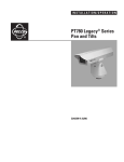
INSTALLATION/OPERATION
®
EH8106L Legacy®
Pressurized Enclosure
C1420M-G (12/04)
Contents
Important Safeguards and Warnings . . . . . . . . . . . . . . . . . . . . . . . . . . . . . . . . . . . . . . . . . . . . . . . . . . . . . . . . . . . . . . . . . . . . . . . . . . . . . . . . . . . . . .3
Description . . . . . . . . . . . . . . . . . . . . . . . . . . . . . . . . . . . . . . . . . . . . . . . . . . . . . . . . . . . . . . . . . . . . . . . . . . . . . . . . . . . . . . . . . . . . . . . . . . . . . . . . . .3
Installation . . . . . . . . . . . . . . . . . . . . . . . . . . . . . . . . . . . . . . . . . . . . . . . . . . . . . . . . . . . . . . . . . . . . . . . . . . . . . . . . . . . . . . . . . . . . . . . . . . . . . . . . . .4
Mounting . . . . . . . . . . . . . . . . . . . . . . . . . . . . . . . . . . . . . . . . . . . . . . . . . . . . . . . . . . . . . . . . . . . . . . . . . . . . . . . . . . . . . . . . . . . . . . . . . . . . . . .4
Camera and Lens Installation . . . . . . . . . . . . . . . . . . . . . . . . . . . . . . . . . . . . . . . . . . . . . . . . . . . . . . . . . . . . . . . . . . . . . . . . . . . . . . . . . . . . . . .4
Mating Connector Assembly . . . . . . . . . . . . . . . . . . . . . . . . . . . . . . . . . . . . . . . . . . . . . . . . . . . . . . . . . . . . . . . . . . . . . . . . . . . . . . . . . . . . . . . .6
Recharging the Enclosure . . . . . . . . . . . . . . . . . . . . . . . . . . . . . . . . . . . . . . . . . . . . . . . . . . . . . . . . . . . . . . . . . . . . . . . . . . . . . . . . . . . . . . . . . .7
Power Connection . . . . . . . . . . . . . . . . . . . . . . . . . . . . . . . . . . . . . . . . . . . . . . . . . . . . . . . . . . . . . . . . . . . . . . . . . . . . . . . . . . . . . . . . . . . . . . . .7
Operation . . . . . . . . . . . . . . . . . . . . . . . . . . . . . . . . . . . . . . . . . . . . . . . . . . . . . . . . . . . . . . . . . . . . . . . . . . . . . . . . . . . . . . . . . . . . . . . . . . . . . . . . . . .7
Maintenance . . . . . . . . . . . . . . . . . . . . . . . . . . . . . . . . . . . . . . . . . . . . . . . . . . . . . . . . . . . . . . . . . . . . . . . . . . . . . . . . . . . . . . . . . . . . . . . . . . . . . . . . .7
Servicing . . . . . . . . . . . . . . . . . . . . . . . . . . . . . . . . . . . . . . . . . . . . . . . . . . . . . . . . . . . . . . . . . . . . . . . . . . . . . . . . . . . . . . . . . . . . . . . . . . . . . . . . . . . .8
Disassembly . . . . . . . . . . . . . . . . . . . . . . . . . . . . . . . . . . . . . . . . . . . . . . . . . . . . . . . . . . . . . . . . . . . . . . . . . . . . . . . . . . . . . . . . . . . . . . . . . . . . .8
Recharging and Reassembly . . . . . . . . . . . . . . . . . . . . . . . . . . . . . . . . . . . . . . . . . . . . . . . . . . . . . . . . . . . . . . . . . . . . . . . . . . . . . . . . . . . . . . . .8
Specifications . . . . . . . . . . . . . . . . . . . . . . . . . . . . . . . . . . . . . . . . . . . . . . . . . . . . . . . . . . . . . . . . . . . . . . . . . . . . . . . . . . . . . . . . . . . . . . . . . . . . . . . .9
List of Illustrations
1
2
3
2
EH8106L Enclosure - Rear View . . . . . . . . . . . . . . . . . . . . . . . . . . . . . . . . . . . . . . . . . . . . . . . . . . . . . . . . . . . . . . . . . . . . . . . . . . . . . . . . . . . . . .5
EH8106L Enclosure - Wiring Diagram . . . . . . . . . . . . . . . . . . . . . . . . . . . . . . . . . . . . . . . . . . . . . . . . . . . . . . . . . . . . . . . . . . . . . . . . . . . . . . . . .5
EH8106L Enclosure Dimension Drawing . . . . . . . . . . . . . . . . . . . . . . . . . . . . . . . . . . . . . . . . . . . . . . . . . . . . . . . . . . . . . . . . . . . . . . . . . . . . . .10
C1420M-G (12/04)
Important Safety Instructions
Prior to installation and use of this product, the following WARNINGS should be observed.
1. Installation and servicing should be done only by qualified service personnel and conform to all local codes.
2. Unless the unit is specifically marked as a NEMA Type 3, 3R, 3S, 4, 4X, 6, or 6P enclosure, it is designed for indoor use only and it must not
be installed where exposed to rain and moisture.
3. Only use replacement parts recommended by Pelco.
4. After replacement/repair of this unit’s electrical components, conduct a resistance measurement between line and exposed parts to verify
the exposed parts have not been connected to line circuitry.
5. The installation method and materials should be capable of supporting four times the weight of the enclosure, pan and tilt, camera and lens
combination.
The product and/or manual may bear the following marks:
This symbol indicates that dangerous voltage constituting a risk of electric
shock is present within this unit.
This symbol indicates that there are important operating and maintenance
instructions in the literature accompanying this unit.
CAUTION:
RISK OF ELECTRIC SHOCK.
DO NOT OPEN.
Please thoroughly familiarize yourself with the information in this manual prior to installation and operation.
Description
The EH8106L is a sealed and pressurized camera enclosure designed for use with PT780 Series Legacy® pan and tilts. The enclosure has lens
preset capabilities and is designed for cameras with fixed focal length or motorized zoom lenses. Two 40-watt heaters are also standard with the
enclosure.
The EH8106L makes use of the Legacy Series system of integral CCTV components. Legacy components make the installation of the pan and tilt
and enclosure fast and easy. The RediLINK® connector is a feature that attaches the enclosure mechanically and electrically to the pan and tilt in
one easy step.
C1420M-G (12/04)
3
Installation
MOUNTING
To attach the enclosure to the pan and tilt unit, perform the following installation steps.
1. Make sure the tilt shaft on the pan and tilt unit is near horizontal so that the connector in the tilt shaft is pointing upward.
2. Lift the housing over the pan and tilt unit, and align the connector in the bottom of the enclosure to the mating connector in the top of the
pan and tilt unit.
3. Place the enclosure down onto the pan and tilt unit. Move the enclosure side-to-side and back and forth as required to mate the two
connectors. Once the two units are mated, apply firm pressure downward and to the back of the enclosure to fully seat the enclosure to the
pan and tilt unit.
4. Balance the enclosure on the pan and tilt. Tighten the two screws in the back of the RediLINK clamp with a 3/32-inch Allen wrench.
CAMERA AND LENS INSTALLATION
To install the camera and lens, perform the following steps:
1. Remove the rear plate of the enclosure. Refer to Figure 1 and do the following:
a.
Remove the spiral retaining ring from the back of the enclosure. Use a screwdriver to pry the end of the spiral retaining ring from the
retaining ring groove.
b.
Pull on the T-handle to remove the rear plate from the housing.
2. Slide the sled out of the enclosure.
3. Remove the desiccant bag from the camera sled. Do not discard the bag.
4. Mount the camera and lens onto the sled:
a.
Extend the lens to the maximum length before positioning the camera and lens.
b.
Position the camera and lens so that they do not extend beyond the track.
c.
Fasten the camera and lens to the sled. Fastener is not supplied.
5. Connect wiring for camera power, lens functions, and video. Refer to Figure 2.
6. Unwrap and install the desiccant bag inside the enclosure.
7. Reinstall the camera sled by sliding it back into the enclosure body. Secure with the spiral retaining ring.
8. Pressurize the inside of the enclosure and assemble the mating connector. Refer to the sections Recharging the Enclosure and Mating
Connector Assembly.
4
C1420M-G (12/04)
SCHRAEDER
VALVE
PRESSURE
RELIEF VALVE
RETAINING
SPRING
END
GROUND STUD
SPIRAL
RETAINING
SPRING
T-HANDLE
HTR
AC LINE
AC NEUT
Figure 1. EH8106L Enclosure - Rear View
GROUND
HTR
THERMOSTAT
A
B
C
L
K
M
N
P
D
E
S
J
R
F G
PP ZOOM
PP FOCUS
PP COM
IRIS
FOCUS
ZOOM
COLOR
COAX CORE
COAX SHIELD
BLK/WHT
RED/WHT
BLU
VIO
GRN/WHT
BLK
WHT/GRN
BRN
RED
ORG
COM YEL
WHT
YEL/WHT
GRY/WHT
LENS
COM
PP +5V
TABLE A
PIN NO.
FUNCTION
A
VIDEO
B
VIDEO
C
PP +5V
D
PP COM
E
CAMERA AC LINE
F
CAMERA AC NEUT
G
PS SWITCH
H
AC LINE
J
PS SWITCH
K
IRIS
L
FOCUS
M
ZOOM
N
LENS
P
AC NEUTRAL
R
PP FOCUS
S
PP ZOOM
Figure 2. EH8106L Enclosure - Wiring Diagram
C1420M-G (12/04)
5
MATING CONNECTOR ASSEMBLY
To assemble the 16-pin mating connector, perform the following
steps:
1. Discard the white plastic sleeve that is included with the
connector assembly. Thread the cable through the
compression nut/strain relief and connector shell.
4. Solder the individual conductors to the appropriate pins in
the back of the connector (refer to Figure 2). Push the
rubber grommet into the back of the connector.
BACK OF CONNECTOR
CONNECTOR
SHELL
GROMMET
COMPRESSION NUT
AND STRAIN RELIEF
2. Prepare the cabling by doing the following:
Control Cable
a.
Strip the outer jacket back 2 inches (5 cm).
b.
Strip the individual conductors back 1/4-inch (6 mm)
and thread them into the appropriate holes through
the rubber grommet. Refer to Figure 2.
5. Screw the connector shell to the back of the connector
and tighten. Tighten the compression nut/strain relief as
far as possible to compress the sealing ring inside the
shell. Attach the cable clamps to the compression nut/
strain relief.
RUBBER
GROMMET
THREADED END
COMPRESSION NUT
AND STRAIN RELIEF
CONNECTOR
SHELL
CABLE CLAMP
THREADED END
3. Assemble the back of the connector.
6
C1420M-G (12/04)
RECHARGING THE ENCLOSURE
You may use your own charging equipment or Pelco’s EH8000RKIT to recharge the enclosure. If you are using your own equipment, adjust the
regulator for an output pressure of 12 psi (83 kPa). If you are using the EH8000RKIT, it uses a regulator with a fixed, nonadjustable output pressure of 12 psi (83 kPa). The gauge reads the tank pressure only.
Refer to Figure 1 and do the following to pressurize the inside of the enclosure with nitrogen:
1. Open the tank valve of the charging kit.
2. Remove the cap from the enclosure’s Schraeder valve and then attach the air chuck from the charging equipment to the valve.
3. To reduce the purge time necessary to remove air from the enclosure, position the enclosure so that the window is pointing up.
4. Remove the plastic cap on the pressure relief valve on the rear of the enclosure. Use a small screwdriver and hold the valve open. Allow the
nitrogen to flow through the enclosure until the humidity indicator registers the lowest humidity level, changing color from pink to blue.
(The humidity indicator can be viewed through the front window of the enclosure looking at the inside top of the enclosure.) Once the
humidity indicator registers the lowest level, remove the screwdriver and allow nitrogen to continue to flow into the enclosure until you no
longer hear the flow of nitrogen from the tank to the enclosure.
5. Remove the charging equipment air chuck from the Schraeder valve. Replace the Schraeder valve and pressure relief valve caps.
POWER CONNECTION
1. Connect ground wire to the ground stud on the back of the enclosure.
2. Connect the mating connector to the rear of the enclosure.
Operation
The heaters are thermostatically controlled to come on at 40°F (4°C) and go off at 60°F (16°C).
Maintenance
At a minimum, the enclosure should be recharged once a year. Also, recharge the enclosure after opening for servicing. Refer to the Servicing
section for instructions on how to disassemble, reassemble, and charge the enclosure.
C1420M-G (12/04)
7
Servicing
DISASSEMBLY
CAUTION: Pressure must be released prior to opening the enclosure or personal injury may result.
1. Disconnect the power from the enclosure.
2. Remove the mating connector from the rear of the enclosure by turning the outer ring counterclockwise until a click is felt; then pull the
mating portion of the connector off. You may elect to remove the enclosure from its mount, which will make the disassembly process much
easier.
3. Remove the center cap from the Schraeder valve. Refer to Figure 1.
4. Relieve internal enclosure pressure by depressing and holding down the center stem of the Schraeder valve.
5. Remove the rear plate of the enclosure. Refer to Figure 1 and do the following:
a.
Remove the spiral retaining ring from the back of the enclosure. Use a screwdriver to pry the end of the spiral retaining ring from the
retaining ring groove.
b.
Pull on the T-handle to remove the rear plate from the housing.
RECHARGING AND REASSEMBLY
Whenever the enclosure is disassembled for servicing, it should be recharged after reassembly and prior to installation. Recharging requires the
use of a Pelco EH8000RKIT recharge kit (or equivalent) and O-ring kit, part number EH8006ORKIT.
To prepare the enclosure for recharging, follow the steps below.
1. Once the enclosure has been disassembled, remove the O-ring from the rear plate and install a new O-ring in the O-ring groove in the rear
plate.
2. When the new O-ring has been installed in the rear plate, smear a liberal amount of the O-ring lubricant provided with the kit on the
exterior surface of the O-ring and rear plate. Replace the desiccant bag in the enclosure with a new one provided with the kit.
3. Slide the camera sled back into the body making sure the front lip of the sled is under the retaining bracket of the enclosure. When fully
installed, the rear plate will fit firmly into the rear opening of the housing and the retaining groove will be fully visible.
4. Reinstall the spiral retaining ring in the retaining groove in the rear of the enclosure.
5. Recharge the enclosure. Refer to the section Recharging and Reassembly for instructions.
8
C1420M-G (12/04)
Specifications
Electrical
Input Voltage
120 VAC (230 VAC optional) for heaters
Power Requirements
160 watts
Connector
16-pin jam nut receptacle
Maximum Cable Distances
12 AWG
14 AWG
16 AWG
18 AWG
20 AWG
Heater
Two 40 watt, 120 VAC. Heaters are thermostatically controlled to activate ON at 40°F (4°C) and OFF at
60°F (16°C)
2,640 ft (804 m)
1,660 ft (505 m)
1,040 ft (316 m)
650 ft (198 m)
410 ft (124 m)
General
Construction
Aluminum 6061 T6
Finish
Outside
Inside
Polyester powder coat
Black anodized
Dimensions
See Figure 3
Front Window
6-inch diameter tempered glass, 0.225-inch thick
Maximum Camera/Lens Size
5” diameter x 18” long (12.7 x 45.72 cm)
or
18” L x 4.0” W x 4.0” H inches (45.72 x 10.16 x 10.16 cm)
Enclosure Mounting
Adjustable cradle secured with stainless steel bands
Purge Fitting
Standard Schraeder valve to allow enclosure to be filled with dry nitrogen
Purge Relief Fitting
Prevents over-pressurization of enclosure
Weight
16 lb (7.25 kg)
Ratings
Meets NEMA Type 6 and IP 67 standards
C1420M-G (12/04)
9
ENVIRONMENTAL
Ambient Operating Temperature
-40° to 122°F (-40° to 50°C) (with heater)
Vibration
5 to 60 Hz with 0.082 inch total travel (15 g’s at 60 Hz). From 60 to 1,000 Hz, 5 g’s rms with
random vibration.
Altitude
Sea level to equivalent of 10,000 feet (32,800 m)
Acoustic Noise
Operates in 150 dB acoustic noise environments
Humidity
Up to 100% relative humidity. Equipped with standard Schraeder and pressure relief valves provide positive internal pressure with dry nitrogen.
(Design and product specifications subject to change without notice.)
Figure 3. EH8106L Enclosure Dimension Drawing
10
C1420M-G (12/04)
PRODUCT WARRANTY AND RETURN INFORMATION
WARRANTY
Pelco will repair or replace, without charge, any merchandise proved defective in material or
workmanship for a period of one year after the date of shipment.
Exceptions to this warranty are as noted below:
• Five years on FT/FR8000 Series fiber optic products and the following fixed camera models:
CC3701H-2, CC3701H-2X, CC3751H-2, CC3651H-2X, MC3651H-2, and CC3651H-2X.
• Three years on all other fixed camera models (including Camclosure® Integrated Camera
Systems) and Genex® Series (multiplexers, server, and keyboard).
• Two years on all standard motorized or fixed focal length lenses.
If a warranty repair is required, the Dealer must contact Pelco at (800) 289-9100 or
(559) 292-1981 to obtain a Repair Authorization number (RA), and provide the following
information:
1. Model and serial number
2. Date of shipment, P.O. number, Sales Order number, or Pelco invoice number
3. Details of the defect or problem
If there is a dispute regarding the warranty of a product which does not fall under the
warranty conditions stated above, please include a written explanation with the product
when returned.
Method of return shipment shall be the same or equal to the method by which the item was
received by Pelco.
®
• Two years on Legacy , CM6700/CM6800/CM8500/CM9500/CM9700 Series Matrix, DF5
and DF8 Series Fixed Dome products.
®
®
• Two years on Spectra , Esprit , and PS20 Scanners, including when used in continuous
motion applications.
• Two years on Esprit® and WW5700 Series window wiper (excluding wiper blades).
• Eighteen months on DX Series digital video recorders and NVR300 Series network video
recorders.
• One year (except video heads) on video cassette recorders (VCRs). Video heads will be
covered for a period of six months.
• Six months on all pan and tilts, scanners or preset lenses used in continuous motion
applications (that is, preset scan, tour and auto scan modes).
Pelco will warrant all replacement parts and repairs for 90 days from the date of Pelco
shipment. All goods requiring warranty repair shall be sent freight prepaid to Pelco, Clovis,
California. Repairs made necessary by reason of misuse, alteration, normal wear, or accident
are not covered under this warranty.
Pelco assumes no risk and shall be subject to no liability for damages or loss resulting from
the specific use or application made of the Products. Pelco’s liability for any claim, whether
based on breach of contract, negligence, infringement of any rights of any party or product
liability, relating to the Products shall not exceed the price paid by the Dealer to Pelco for
such Products. In no event will Pelco be liable for any special, incidental or consequential
damages (including loss of use, loss of profit and claims of third parties) however caused,
whether by the negligence of Pelco or otherwise.
The above warranty provides the Dealer with specific legal rights. The Dealer may also have
additional rights, which are subject to variation from state to state.
RETURNS
In order to expedite parts returned to the factory for repair or credit, please call the factory at
(800) 289-9100 or (559) 292-1981 to obtain an authorization number (CA number if returned
for credit, and RA number if returned for repair).
All merchandise returned for credit may be subject to a 20% restocking and refurbishing
charge.
Goods returned for repair or credit should be clearly identified with the assigned CA or RA
number and freight should be prepaid. Ship to the appropriate address below.
If you are located within the continental U.S., Alaska, Hawaii or Puerto Rico, send goods to:
Service Department
Pelco
3500 Pelco Way
Clovis, CA 93612-5699
If you are located outside the continental U.S., Alaska, Hawaii or Puerto Rico and are
instructed to return goods to the USA, you may do one of the following:
If the goods are to be sent by a COURIER SERVICE, send the goods to:
Pelco
3500 Pelco Way
Clovis, CA 93612-5699 USA
If the goods are to be sent by a FREIGHT FORWARDER, send the goods to:
Pelco c/o Expeditors
473 Eccles Avenue
South San Francisco, CA 94080 USA
Phone: 650-737-1700
Fax: 650-737-0933
REVISION HISTORY
Manual #
C1420M
C1420M-A
C1420M-B
Date
1/95
4/95
5/96
C1420M-C
C1420M-D
5/96
7/97
6/98
11/98
7/00
C1420M-E
C1420M-F
C1420M-G
1/04
12/04
12/04
Comments
Original version.
Rev. A. Incorporates changes in Section 4.0 and Figure 1 for unit weights and dimensions and maximum camera/lens dimensions per ECO #95-042.
Rev. B. Incorporates changes in heater blankets and brackets per ECO #96-147. Part references updated accordingly and Figure 3 redone. Pressure switch
information added per ECO # 95-220.
Rev. C. Figure 3 reused to remove pressure sensor switch. Refer to manual C1445M for switch wiring. Figure 5 and Section 8.2 revised to include grounding lug.
Section 7.3, step 4 revised (color: pink to blue). Added new Section 3.2 for CE and UL compliance.
Removed references to UL compliance. Changed format.
Revised Figure 4. Editing changes.
Revised manual to include grounding stud on rear plate. Revised mating connector assembly instructions and diagram. Moved exploded assembly diagram and parts
lists to new maintenance/service manual (C1420SM). Removed installation instructions for sun shroud, which has separate manual. Updated manual to new format.
Revised enclosure pressure from 5 psi to 8 psi.
Factory preset for regulator changed to 12 psi per ECO# 04-9807. Updated layout.
Revised instructions and artwork for mating connector assembly per ECO #04-10254.
Pelco, the Pelco logo, Spectra, Genex, Legacy, Esprit, and
Camclosure are registered trademarks of Pelco.
© Copyright 2004, Pelco.
All rights reserved.
®
Worldwide Headquarters
3500 Pelco Way
Clovis, California 93612 USA
USA & Canada
Tel: 800/289-9100
Fax: 800/289-9150
International
Tel: 1-559/292-1981
Fax: 1-559/348-1120
www.pelco.com
ISO9001
United States
|
Canada
|
United Kingdom
|
The Netherlands
|
Singapore
|
Spain
|
Scandinavia
|
France
|
Middle East