1
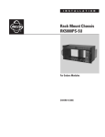
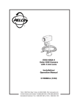
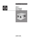
®
MLZ6DT
Motorized Zoom Lens Control
Installation/Operation Manual
C517M Rev C (6/92)
1.0 WARNINGS
CAUTION:
RISH OF ELECTRIC SHOCK.
DO NOT OPEN.
Prior to installation and use of this product, the following
WARNINGS should be observed.
1.
Installation and servicing should only be done by
Qualified Service Personnel and conform to all
Local codes.
2.
Unless the unit is specifically marked as a NEMA
Type 3, 3R, 3S, 4, 4X, 6, or 6P enclosure, it is
designed for indoor use only and it must not be
installed where exposed to rain and moisture.
3.
The product bears the following marks:
This symbol indiates that dangerous
voltage constituting a risk of electric
shock is present within this unit.
This symbol indicates that there are
important operating and maintenance instructions in the literature
accompanying this unit.
4.
Only use replacement parts recommended by Pelco.
5.
After replacement/repair of this unit’s electrial
components, conduct resistance measurements
between line and exposed parts to verify the exposed
parts have not been connected to line circuitry.
Please thoroughly familiarize yourself with the information in this manual prior to installation and operation.
CAUTION:
TO REDUCED THE RISK OF ELECTRIAL SHOCK,
DO NOT REMOVE COVER. NO USER-SERVICEABLE PARTS INSIDE. REFER SERVICING TO
QUALIFIED SERVICE PERSONNEL.
Pelco • 3500 Pelco Way, Clovis, CA 93612-5699 • USA • www.pelco.com
(800) 289-9100 or (1-559) 292-1981 • FAX (800) 289-9150 or (1-559) 292-3827
International customers call (1-559) 292-1981 or FAX (1-559) 348-1120
2.0 SCOPE
3.1 OPTIONS
The information contained within this manual covers
the MLZ6DT Motorized Zoom Lens Control with the
24 VAC wall mount transformer power supply.
AI701
Auto-iris servo for motorized zoom
lenses with “ND” and “MS” in suffix.
Allows for fully automatic iris operation with manual override when used
with MLZ6DT lens control.
C06HWC
Pre-wired, 6 foot (1.82 m) interconnecting with 14-pin control connector and butt splices on mating end.
(Compatible only when not used with
the AI701.)
(UL)
DT200
Dual desk top mount kit; two units
can be mounted side-by-side in one
desk top chassis.
R300
Rack mount kit for up to three (3)
control modules.
3.0 DESCRIPTION
The MLZ6DT is a desk top zoom lens control which
provides remote control of zoom, focus, and iris functions for all Pelco motorized zoom lenses.
The MLZ6DT can also be used with lenses equipped
with the AI700/AI701 auto iris servo assembly.
The servo in the AI700/AI701 detects the slightest
change in video level and drives the iris motor to open
or close the iris to maintain proper faceplate illumination. The MLZ6DT control allows for manual override
of the auto iris functions for scenes requiring manual
iris adjustment.
Front panel switches provide control of zoom and focus functions, with optional manual control of the iris.
Speed is adjustable through the front panel knob control.
2
Pelco Manual C517M Rev C (6/92)
4.0 INSTALLATION
4.
The contact pins supplied with the mating connector are the “crimp” type which may also be soldered if you so desired (item 4).
5.
After crimping or soldering the contact pins to the
conductors, push them into the proper holes in the
connector until they snap in place.
4.1 CONNECTOR ASSEMBLY
Installation and/or testing will require you to assemble
the connector parts provided. Fabricate the interconnecting cable according to the following steps (reference Figure 1).
NOTE: Contacts cannot be removed from the
connector without the use of the appropriate
AMP extraction tool which is available from
Pelco.
1.
Slide part A of the cable clamp (item 1) over the end
of the cable (item 1, part C) with the threaded end
of the cable clamp facing the connector (item 5).
2.
If the cable has a diameter less than 1/2 inch (1.3
cm), slide the rubber boot (item 2) over the end of
the cable and pull through the cable clamp to so that
the boot encases the cable and forms a good seal.
6.
Slide part A of the cable clamp toward the connector and screw the parts together. Attach part B (item
1) onto part A and connect both parts with the
screws provided.
3.
Strip back the cable jacket approximately 1-1/4
inches (3.2 cm) and separate the individual conductors (item 3).
7.
Connect the cable assembly to the unit and seat
the connector by twisting the locking collar until it
snaps into position.
Refer to Figure 2 for wiring diagram.
5
1
threaded end of
cable clamp
A
B
C
STEP 1
5
1
FLEXIBLE RUBBER BOOT
A
B
STEP 2
C
2
5 **
3
4
1
A
STRIP 1/8"
B
C
STEPS 3-7
CRIMP
INSULATION
CRIMP
WIRE
OUTSIDE
JACKET
OF CABLE
STRIP 1"
**
ITEM 5 DETAIL
4
1
9
10
2
1
3
5
15
4
8
23
33
37
34
FRONT VIEW
37-PIN CONNECTOR
29
3
9
14
16
22
28
15
20
25
21
28
3
10
1
7
14
26
FRONT VIEW
28-PIN CONNECTOR
11
16
15
FRONT VIEW
16-PIN CONNECTOR
3
1
4
7
4
6
THE MOST COMMONLY USED
CONNECTOR PIN-OUT CONFIGURATIONS ARE SHOWN HERE.
REFERENCE THE CONNECTOR
DRAWING APPLICABLE TO
YOUR SITUATION.
1
6
11
8
14
9
7
12
FRONT VIEW
14-PIN CONNECTOR
FRONT VIEW
9-PIN CONNECTOR
Figure 1. Connector Assembly
Pelco Manual C517M Rev C (6/92)
3
1
3
1
12
14
2
6
3
5
4
10
IRIS
1
RED
2
MANUAL IRIS*
5
BLUE
13
LENS COM
4
BLK
12
ZOOM
2
WHT
8
GND
G
YEL
11
FOCUS
3
GRN
CONTROL
OUTPUT
P3
LENS INPUT
*NO CONNECTION REQUIRED EXCEPT WHEN USED WITH A1700.
ALLOWS MANUAL IRIS CONTROL.
Figure 2. Wiring Diagram for Output Pin Assignments
4
Pelco Manual C517M Rev C (6/92)
5.0 OPERATION AND SYSTEM TEST
1.
Hook up the control cable between the output connector on MLZ6DT and the input connector on the
lens (see Figure 3).
2.
Check that the video is connected from the camera
to the monitor.
3.
Plug the mating connector of the wall mount transformer into the back of the MLZ6DT and plug the
transformer into a 120 VAC source. The power indicator LED will light when power is applied.
4.
For manual operation, put the switch in the
MANUAL position. Observing the monitor, test
for proper operation of zoom, focus, and iris functions with related switches on the front panel.
5.
NOTE: AUTO operation only works in conjunction with AI700 or AI701 auto iris servo
units. If the lens is equipped with AI700 or
AI701, use the following guidelines to test auto
operation (see Figure 4).
6.
Connect the AI700 or AI701 as shown in Figure 4.
Put the power switch in the AUTO/ON position. The
IRIS switch should not operate; ZOOM and FOCUS switches should operate normally. Observing
the monitor, test operation of ZOOM and FOCUS
switches. Next, turn the lens toward a dark area, and
observing the monitor, check that the iris opens.
Move the lens back toward a lighter area, and observing the monitor, check that the iris closes.
6.0 MAINTENANCE
Under normal operating conditions and usage, maintenance of this equipment is not necessary. However, if
maintenance should be required, consult Pelco or a
qualified service technician.
Test for fast and slow speeds of all functions by
observing their operation as the LENS SPEED
knob on the front panel is adjusted.
COAX CABLE
WALL MOUNT
TRANSFORMER
CONTROL CABLE
MLZ6
Figure 3. Basic System Configuration
COAX CABLE
AI700
A1700
WALL MOUNT
TRANSFORMER
CONTROL CABLE
MLZ6
(A1700REQUIRES
REQUIRESEXTERNAL
EXTERNAL
(AI700
POWERSUPPLY)
SUPPLY)
POWER
Figure 4. System Configuration Using AI700 or AI701 Auto Iris Servo
Pelco Manual C517M Rev C (6/92)
5
7.0 SCHEMATIC
Figure 5. MLZ6DT Schematic
6
Pelco Manual C517M Rev C (6/92)
8.0 SPECIFICATIONS
CONTROLS
Zoom:
Focus:
Manual Iris:
Auto-Iris:
Video Level:
Speed:
On/Off:
Pilot Lamp:
Paddle switch TELE/WIDE
Paddle switch NEAR/FAR
Paddle switch OPEN/CLOSE
Paddle switch AUTO/MANUAL
Knob adjustment (MLZA6DT only)
Knob adjustment
Rocker switch
Light emitting diode (LED)
(MLZ6DT)
Long life neon (MLZA6DT)
Cable Distances: The following distances are approximate maximum recommended under
the following conditions:
— Based on a 35mA load @ 9 VDC
— Single lens function activation
— Single common conductor in lens
cable
— 10% loss in voltage
22 Awg
797 feet (243 m)
20 Awg 1,267 feet (386 m)
18 Awg 2,015 feet (614 m)
NOTE: Video is limited to 500 feet on RG59 coax cable without equalization amplifier.
ELECTRICAL
GENERAL
Input Voltage:
Output Voltage:
Power
Consumption:
Power Supply:
Output
Connector:
Circuit:
Cable
Requirements:
120 or 230 VAC, 50/60 Hz
±2-12 VDC
3-6 watts
24 VAC, CT 400 mA wall mount
transformer (MLZ6DT)
Construction:
Cover
Chassis
Panel
Dimensions
AMP CPC type, 14-pin (mate supplied)
Full wave power supply with solidstate drive
Four (4) conductors plus ground; one
(1) additional conductor for manual
override
Steel, black polyester powder coat
Steel, zinc plated
Aluminum, black polyester powder
coat with white silkscreen
See Figure 6
Weight
MLZ6DT Series
MLZA6DT Series
Rating:
Unit
3 lbs (1.35 kg)
4 lbs (1.8 kg)
Shipping
5 lbs (2.25 kg)
6 lbs (2.7 kg)
NEMA 1
Figure 6. MLZ6DT Dimension Drawing
Pelco Manual C517M Rev C (6/92)
7
9.0 WARRANTY AND RETURN
INFORMATION
WARRANTY
RETURNS
Pelco will repair or replace, without charge, any merchandise proved
defective in material or workmanship for a period of one year after the date
of shipment.
Exceptions to this warranty are as noted below:
In order to expedite parts returned to the factory for repair or credit, please
call the factory at (800) 289-9100 or (559) 292-1981 to obtain an
authorization number (CA number if returned for credit, and RA number
if returned for repair).
• Five years on FT/FR8000 Series fiber optic products.
All merchandise returned for credit may be subject to a 20% restocking
and refurbishing charge.
• Three years on Genex® Series products (multiplexers, server, and
keyboard).
• Three years on Camclosure® and fixed camera models, except the
CC3701H-2, CC3701H-2X, CC3751H-2, CC3651H-2X, MC3651H-2,
and MC3651H-2X camera models, which have a five-year warranty.
• Two years on standard motorized or fixed focal length lenses.
• Two years on Legacy®, CM6700/CM6800/CM9700 Series matrix, and
DF5/DF8 Series fixed dome products.
• Two years on Spectra®, Esprit®, ExSite™, and PS20 scanners, including when used in continuous motion applications.
• Two years on Esprit® and WW5700 Series window wiper (excluding
wiper blades).
• Eighteen months on DX Series digital video recorders, NVR300
Series network video recorders, and Endura ™ Series distributed
network-based video products.
• One year (except video heads) on video cassette recorders (VCRs).
Video heads will be covered for a period of six months.
• Six months on all pan and tilts, scanners or preset lenses used in
continuous motion applications (that is, preset scan, tour and auto scan
modes).
Pelco will warrant all replacement parts and repairs for 90 days from the
date of Pelco shipment. All goods requiring warranty repair shall be sent
freight prepaid to Pelco, Clovis, California. Repairs made necessary by
reason of misuse, alteration, normal wear, or accident are not covered
under this warranty.
Pelco assumes no risk and shall be subject to no liability for damages or
loss resulting from the specific use or application made of the Products.
Pelco’s liability for any claim, whether based on breach of contract,
negligence, infringement of any rights of any party or product liability,
relating to the Products shall not exceed the price paid by the Dealer to
Pelco for such Products. In no event will Pelco be liable for any special,
incidental or consequential damages (including loss of use, loss of profit
and claims of third parties) however caused, whether by the negligence
of Pelco or otherwise.
The above warranty provides the Dealer with specific legal rights. The
Dealer may also have additional rights, which are subject to variation from
state to state.
If a warranty repair is required, the Dealer must contact Pelco at (800)
289-9100 or (559) 292-1981 to obtain a Repair Authorization number
(RA), and provide the following information:
Goods returned for repair or credit should be clearly identified with the
assigned CA or RA number and freight should be prepaid. Ship to the
appropriate address below.
If you are located within the continental U.S., Alaska, Hawaii or Puerto
Rico, send goods to:
Service Department
Pelco
3500 Pelco Way
Clovis, CA 93612-5699
If you are located outside the continental U.S., Alaska, Hawaii or Puerto
Rico and are instructed to return goods to the USA, you may do one of the
following:
If the goods are to be sent by a COURIER SERVICE, send the goods to:
Pelco
3500 Pelco Way
Clovis, CA 93612-5699 USA
If the goods are to be sent by a FREIGHT FORWARDER, send the goods
to:
Pelco c/o Expeditors
473 Eccles Avenue
South San Francisco, CA 94080 USA
Phone: 650-737-1700
Fax: 650-737-0933
1. Model and serial number
2. Date of shipment, P.O. number, Sales Order number, or Pelco invoice
number
3. Details of the defect or problem If there is a dispute regarding the
warranty of a product which does not fall under the warranty conditions
stated above, please include a written explanation with the product
when returned.
Method of return shipment shall be the same or equal to the method by
which the item was received by Pelco.
This equipment contains electrical or electronic components that must be recycled properly to comply with Directive 2002/96/EC of the European Union
regarding the disposal of waste electrical and electronic equipment (WEEE). Contact your local dealer for procedures for recycling this equipment.
8
Pelco Manual C517M Rev C (6/92)