1
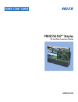
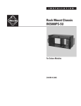
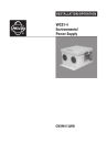
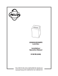
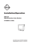
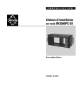
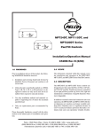
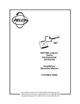
®
MPT9008PZ/CZ
Coaxitron Switcher/Controller
Installation/Operation Manual
C558M (3/96)
Pelco • 3500 Pelco Way, Clovis, CA 93612-5699 • USA • www.pelco.com
(800) 289-9100 or (1-559) 292-1981 • FAX (800) 289-9150 or (1-559) 292-3827
International Customers: Tel (1-559) 292-1981 or FAX (1-559) 348-1120
TABLE OF CONTENTS
Section
Page
1.0
WARNINGS ...................................................................................................................................... 1
2.0
SCOPE ............................................................................................................................................. 2
3.0
DESCRIPTION ................................................................................................................................. 2
4.0
INSTALLATION ................................................................................................................................. 3
4.1 TERMINATING CONFIGURATION ........................................................................................... 3
4.2 NONTERMINATING LOOP-THROUGH CONFIGURATION ..................................................... 3
5.0
OPERATION ..................................................................................................................................... 5
5.1 SWITCHER/CONTROLLER ...................................................................................................... 5
5.1.1 Controls ........................................................................................................................... 5
6.0
MODELS .......................................................................................................................................... 6
7.0
SPECIFICATIONS ............................................................................................................................ 6
8.0
WARRANTY AND RETURN INFORMATION ................................................................................... 7
Pelco, the Pelco Logo, Camclosure, Esprit, Genex, Legacy, and Spectra are registered trademarks of Pelco.
© Copyright 1996, Pelco. All rights reserved.
Endura and ExSite are trademarks of Pelco.
ii
Pelco Manual C558M (3/96)
LIST OF ILLUSTRATIONS
Figure
1
2
3
4
5
Page
MPT9008CZ–Front View ................................................................................................................... 2
MPT9008CZ–Rear View .................................................................................................................... 3
MPT9008PZ/CZ–Configuring for Loop-Through Operation ............................................................... 4
MPT9008PZ/CZ–Homing/Terminating Configuration ........................................................................ 4
MPT9008PZ/CZ–Homing/Looping Configuration .............................................................................. 5
REVISION HISTORY
Manual #
C558M
Date
3/96
Pelco Manual C558M (3/96)
Comments
Original version
iii
(This page intentionally left blank.)
iv
Pelco Manual C558M (3/96)
INSTALLATION/OPERATION MANUAL
MPT9008PZ/CZ
COAXITRON SWITCHER/CONTROLLER
1.0 WARNINGS
Prior to installation and use of this product, the following
WARNINGS should be observed.
1.
Installation and servicing should only be done by
Qualified Service Personnel and conform to all
Local codes.
2.
Unless the unit is specifically marked as a NEMA
Type 3, 3R, 3S, 4, 4X, 6, or 6P enclosure, it is
designed for indoor use only and it must not be
installed where exposed to rain and moisture.
3.
Only use replacement parts recommended by
PELCO.
4.
After replacement/repair of this unit’s electrical
components, conduct a resistance measurement
between line and exposed parts to verify the exposed
parts have not been connected to line circuitry.
This product may bear the following marks:
This symbol indicates that dangerous voltage
constituting a risk of electric shock is present
within this unit.
This symbol indicates that there are important
operating and maintenance instructions in the
literature accompanying this unit.
CAUTION:
TO REDUCE THE RISK OF ELECTRICAL
SHOCK, DO NOT REMOVE COVER. NO
USER-SERVICEABLE PARTS INSIDE.
REFER SERVICING TO QUALIFIED
SERVICE PERSONNEL.
CAUTION:
RISK OF ELECTRIC SHOCK.
DO NOT OPEN.
Please thoroughly familiarize yourself with the information in this manual
prior to installation and operation.
Pelco Manual C558M (3/96)
1
CAMERA/LENS FUNCTIONS
2.0 SCOPE
The information contained within this manual covers
the installation and operation of the MPT9008PZ/CZ
Coaxitron Switcher/Controller.
Please thoroughly familiarize yourself with the information in this manual prior to installation and operation.
3.0 DESCRIPTION
As the name implies, the MPT9008PZ/CZ Coaxitron
Switcher/Controller is a unit that provides both a Controller and Switcher in the same electronics package.
(Reference Figure 1.) The integration of these dual
functions into one package combines the functionality
of the Coaxitron transmitter/controller and the convenience of an 8-input passive switcher with loop-through
capabilities. The transmitter/controller provides up to
16 remote control functions without the need for control
cables other than for a dedicated video cable for the
normal transmission of a remote camera signal to the
local monitoring and control position. The MPT9008PZ/
CZ lends itself to application in situations where shortto-medium distances are involved.
Typically, these 16 transmitter/control functions can
be grouped as follows:
PTZ FUNCTIONS
1.
2.
3.
4.
Pan Left
Pan Right
Tilt Up
Tilt Down
5.
6.
7.
8.
Zoom In
Zoom Out
Focus Near
Focus Far
9. Iris Open
10. Iris Close
11. Camera Power On/Off
12. Auto/Manual Scan
AUXILIARY FUNCTIONS
13. AUX 1 (Manual Iris)
14. AUX 2 (Auto Iris)
15. AUX 3
16. AUX 4
Functions 1 through 10, 15 and 16 are momentary; that
is, they are only actuated while the associated control
switch located on the Coaxitron Switcher/Controller
front panel is operated. Functions 11, 12, 13 and 14 are
latching; that is, camera power, auto scan, and auto/
manual iris are latching functions and remain on until
turned off. The latching iris function is not dedicated,
and with proper interfacing, it can be used for some
other latching function. Alternately, AUX 1, 2, 3 and 4
may be used as momentary functions to control such
things as lights or gates with proper external interfacing.
Up to ten functions can be operated simultaneously.
Functions 11 through 16 must be used individually;
although any one of these functions may be used simultaneously with functions 1 through 10. These control
functions are active and control only the camera position that is currently selected by the push buttons (1-8)
on the front panel of the unit.
The switcher portion of the MPT9008CZ/PZ provides
a convenient, inexpensive and reliable method of switching up to 8 video inputs, one at a time, to a single monitor
output. All switching is accomplished utilizing interlocked manual push buttons. The number on each push
button corresponds to the video input BNC on the rear
of the unit; i.e., push button #1 corresponds to video
input #1, etc. When any push button is depressed, the
corresponding video input is displayed on the monitor
and coax control functions are enabled for that camera
position.
Figure 1. MPT9008CZ–Front View
2
Pelco Manual C558M (3/96)
The MPT9008PZ/CZ is shipped with terminated BNC
inputs; however, the user can configure the unit for
loop-through operation. See Section 4.2 and Figure 3.
This makes it possible to loop signals through the
MPT9008PZ/CZ switcher/controller to an additional
switcher/controller and monitor at a remote location
where the signal is terminated. Any switcher can be
used at the second location and operate completely
independent of the first location.
4.2 NONTERMINATING LOOP-THROUGH
CONFIGURATION
To configure the MPT9008PZ/CZ for loop-through
operation reference Figure 3 and perform the following
steps:
1.
Remove power from the unit if not already done.
2.
Remove the cover from the unit to expose the BNC
inputs located in the left, rear, back panel area.
3.
Each BNC’s video input has a corresponding, like
numbered, front panel push button. Associated
with each BNC is a resistor as illustrated in Figure
3. Clip only the leads of those resistors whose video
input you wish to configure as being loop-through.
Figure 3, for example, shows the resistor lead for
video input #1 being clipped.
4.
After making the desired changes, replace the cover
and resume operation.
4.0 INSTALLATION
MPT9008PZ/CZ Switcher/Controllers can be installed
in a number of configurations depending on your system requirements. The two basic types of configuration
possibilities are shown in Figures 4 and 5, respectively,
depending on whether or not the unit is configured as
terminating or as loop-through.
4.1 TERMINATING CONFIGURATION
Both models of the switcher/controller are shipped from
the factory as homing, terminated units. See section 4.2
for configuring the MPT9008PZ/CZ for loop-through
operation.
NOTE: Looping switcher/controllers do not have
internal termination. Inputs must be terminated
with 75 ohms by other equipment in the system.
Figure 2. MPT9008CZ–Rear View
Pelco Manual C558M (3/96)
3
Figure 3. MPT9008PZ/CZ–Configuring for Loop-Through Operation
Figure 4. MPT9008PZ/CZ–Homing/Terminating Configuration
4
Pelco Manual C558M (3/96)
Figure 5. MPT9008PZ/CZ–Homing/Looping Configuration
5.0 OPERATION
5.1.1 Controls
In general, all operating controls on the transmitter are
self explanatory. With the exception of the ON/OFF
power switch and the 8-position joystick, all controls
are center-off, spring return paddle switches (momentary on-off-on).
Power ON/OFF
Pan/Tilt
Zoom
Focus
Iris
Aux 1,2
5.1 SWITCHER/CONTROLLER
The transmitter switcher/controller is housed in a 1-3/4"
high enclosure, supplied as either a desk top unit (CZ
suffix) or as a rack mount unit (PZ suffix). Up to eight
video BNC connector inputs are available on the rear of
the unit. Any of these video inputs are switch selectable,
one at a time, to the available monitor and, while
selected, coax control functions for the pan/tilt and
camera are enabled.
Pelco Manual C558M (3/96)
Camera Power
Pan Auto/Man
Aux 3, 4
Rocker switch
8-position joystick
Paddle switch Tele/Wide
Paddle switch Near/Far
Paddle switch Open/Close
Paddle switch Auto/Manual
Iris (latching function)
Paddle switch On/Off (latching
function)
Paddle switch Manual/Auto
(latching function)*
Paddle switch (momentary
functions)*
*External requirements are needed for operation
5
Operating
Distance:
6.0 MODELS
MPT9008CZ
Coaxitron Switcher/Controller
capable of handling and/or
controlling 8 video inputs, one
at a time. 120 VAC input.
MPT9008CZ/220
Same as MPT9008CZ except
230 VAC input.
MPT9008PZ
Same as MPT9008CZ except
rack-mount.
MPT9008PZ/220
Same as MPT9008PZ except
230 VAC input.
Cable distances are approximate
according to cable type used. 75
ohm coax required.
Cable
Type
Distance
Distance
Using EA2000
RG59U
RG6
RG11
RG15
750 ft 9229 m)
1,500 ft (457 m)
1,800 ft (549 m)
—
3,000 ft (914.4 m)
4,500 ft (1,371.6 m)
6,000 ft (1,828.8 m)
8,000 ft (2,438.4 m)
GENERAL
7.0 SPECIFICATIONS
Ambient
Temperature:
ELECTRICAL
Input Voltage:
Power
Consumption:
Control Method:
Pulse Amplitude:
120 VAC, 60 Hz or 230 VAC,
50 Hz
Transmitter 2.5vA
15-pulse train (pulse width
modulated) superimposed on the
video signal during the vertical
blanking interval by the control
transmitter. Pulse train occupies
1 TV line period
-32°F to +120°F
(0°C to +48.89°C)
VIDEO
Inputs:
8 video signal inputs
Video
Connectors:
BNC
Termination:
Input—75 ohm internal termination. Loop-through capability via
clipped leads
Approximately 1V p-p added to
video signal, 333 kHz nominal
Connectors:
Control/
Transmitter
Monitor
16 BNC connectors; 8 for video
inputs, 8 for looping outputs
1 BNC connector
Input Video Level:
1V p-p nominal; 2V p-p maximum at less than 75% APL;
1.5V p-p maximum at 90% APL
Fuse Protection:
3 AG type:
120VAC, 2/10A, SB
230VAC, 1/10A, SB
Power Cord:
6
3-wire grounded #18 AWG
Pelco Manual C558M (3/96)
8.0 WARRANTY AND RETURN
INFORMATION
WARRANTY
RETURNS
Pelco will repair or replace, without charge, any merchandise proved
defective in material or workmanship for a period of one year after the date
of shipment.
Exceptions to this warranty are as noted below:
In order to expedite parts returned to the factory for repair or credit, please
call the factory at (800) 289-9100 or (559) 292-1981 to obtain an
authorization number (CA number if returned for credit, and RA number
if returned for repair).
• Five years on FT/FR8000 Series fiber optic products.
All merchandise returned for credit may be subject to a 20% restocking
and refurbishing charge.
• Three years on Genex® Series products (multiplexers, server, and
keyboard).
• Three years on Camclosure® and fixed camera models, except the
CC3701H-2, CC3701H-2X, CC3751H-2, CC3651H-2X, MC3651H-2,
and MC3651H-2X camera models, which have a five-year warranty.
• Two years on standard motorized or fixed focal length lenses.
• Two years on Legacy®, CM6700/CM6800/CM9700 Series matrix, and
DF5/DF8 Series fixed dome products.
• Two years on Spectra®, Esprit®, ExSite™, and PS20 scanners, including when used in continuous motion applications.
• Two years on Esprit® and WW5700 Series window wiper (excluding
wiper blades).
• Eighteen months on DX Series digital video recorders, NVR300
Series network video recorders, and Endura ™ Series distributed
network-based video products.
• One year (except video heads) on video cassette recorders (VCRs).
Video heads will be covered for a period of six months.
• Six months on all pan and tilts, scanners or preset lenses used in
continuous motion applications (that is, preset scan, tour and auto scan
modes).
Pelco will warrant all replacement parts and repairs for 90 days from the
date of Pelco shipment. All goods requiring warranty repair shall be sent
freight prepaid to Pelco, Clovis, California. Repairs made necessary by
reason of misuse, alteration, normal wear, or accident are not covered
under this warranty.
Pelco assumes no risk and shall be subject to no liability for damages or
loss resulting from the specific use or application made of the Products.
Pelco’s liability for any claim, whether based on breach of contract,
negligence, infringement of any rights of any party or product liability,
relating to the Products shall not exceed the price paid by the Dealer to
Pelco for such Products. In no event will Pelco be liable for any special,
incidental or consequential damages (including loss of use, loss of profit
and claims of third parties) however caused, whether by the negligence
of Pelco or otherwise.
The above warranty provides the Dealer with specific legal rights. The
Dealer may also have additional rights, which are subject to variation from
state to state.
If a warranty repair is required, the Dealer must contact Pelco at (800)
289-9100 or (559) 292-1981 to obtain a Repair Authorization number
(RA), and provide the following information:
Goods returned for repair or credit should be clearly identified with the
assigned CA or RA number and freight should be prepaid. Ship to the
appropriate address below.
If you are located within the continental U.S., Alaska, Hawaii or Puerto
Rico, send goods to:
Service Department
Pelco
3500 Pelco Way
Clovis, CA 93612-5699
If you are located outside the continental U.S., Alaska, Hawaii or Puerto
Rico and are instructed to return goods to the USA, you may do one of the
following:
If the goods are to be sent by a COURIER SERVICE, send the goods to:
Pelco
3500 Pelco Way
Clovis, CA 93612-5699 USA
If the goods are to be sent by a FREIGHT FORWARDER, send the goods
to:
Pelco c/o Expeditors
473 Eccles Avenue
South San Francisco, CA 94080 USA
Phone: 650-737-1700
Fax: 650-737-0933
1. Model and serial number
2. Date of shipment, P.O. number, Sales Order number, or Pelco invoice
number
3. Details of the defect or problem If there is a dispute regarding the
warranty of a product which does not fall under the warranty conditions
stated above, please include a written explanation with the product
when returned.
Method of return shipment shall be the same or equal to the method by
which the item was received by Pelco.
This equipment contains electrical or electronic components that must be recycled properly to comply with Directive 2002/96/EC of the European Union
regarding the disposal of waste electrical and electronic equipment (WEEE). Contact your local dealer for procedures for recycling this equipment.
Pelco Manual C558M (3/96)
7
®
Pelco
3500 Pelco Way, Clovis, CA 93612-5699
(559) 292-1981 • (800) 289-9100
FAX (800) 289-9150 or (559) 292-3827
(Product specifications subject to change without notice.)
C558M
8
Pelco Manual C558M (3/96)