1
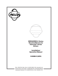
®
IOP08 Series
Intercept®
Camera and Lens
Installation/
Operation Manual
C1441M-D (1/98)
Pelco • 3500 Pelco Way, Clovis • CA 93612-5699 USA • www.pelco.com
In North America and Canada: Tel (800) 289-9100 or FAX (800) 289-9150
International Customers: Tel (1-559) 292-1981 or FAX (1-559) 348-1120
CONTENTS
Section
Page
1.0 GENERAL3
1.1 IMPORTANT SAFEGUARDS AND WARNINGS ............................... 3
2.0 DESCRIPTION .......................................................................................... 4
2.1 MODELS ............................................................................................ 4
3.0 INSTALLATION .......................................................................................... 5
3.1 ADJUSTMENTS ............................................................................... 5
3.1.1 Back Focus ............................................................................. 6
3.1.2 Shutter Speed ......................................................................... 6
3.1.3 Auto Gain Control ................................................................... 6
3.1.4 White Balance (ATW/AWB Switch) ......................................... 6
3.1.5 V-Phase (Vertical Phase) ........................................................ 7
3.1.6 Auto Iris ................................................................................... 7
4.0 SERVICE ................................................................................................... 9
5.0 WIRING DIAGRAM ................................................................................... 10
6.0 SPECIFICATIONS .................................................................................... 11
7.0 WARRANTY AND RETURN INFORMATION ........................................... 12
LIST OF ILLUSTRATIONS
Figure
1
2
3
4
5
Page
Back Focus Adjustment ..................................................................... 5
Color Camera Adjustments ................................................................ 8
Black and White Camera Adjustments ............................................... 8
Camera/Lens Removal and Installation ............................................. 9
Schematic Diagram for Color Camera/Lens ..................................... 10
LIST OF TABLES
Table
A
Page
Shutter Speeds .................................................................................. 8
REVISION HISTORY
Manual #
2
Date
Comments
C1441M
9/95
Original version.
C1441M-A
10/95
Part number changes incorporated. IOP08SXX and
IOP08SXX-PAL changed to IOP083X and IOP084X,
respectively. Sections 6.4 and 6.5 updated with
adjustment instructions. Figures 6 and 7 updated.
C1441M-B
11/96
Added IOP08B3X/IOP08B4X Series. Replaced Figure 7
with new art for black and white cameras and lenses.
Moved shutter speed settings from Figure 7 to Table A.
Revised dimensions in Figures 1 and 2.
C1441M-C
1/98
Revised manual to reduce the number of models.
Changed to new format.
C1441M-D
1/98
Changed model numbers, revised Figure 1, and
removed exploded assembly diagram. Changed manual
pagination.
Pelco Manual C1441M-D (1/98)
1.0 GENERAL
1.1 IMPORTANT SAFEGUARDS AND WARNINGS
Prior to installation and use of this product, the following WARNINGS should be
observed.
1.
Installation and servicing should only be done by Qualified Service Personnel
and conform to all Local codes.
2.
Unless the unit is specifically marked as a NEMA Type 3, 3R, 3S, 4, 4X, 6, or
6P enclosure, it is designed for indoor use only and it must not be installed
where exposed to rain and moisture.
3.
Only use replacement parts recommended by Pelco.
4.
After replacement/repair of this unit’s electrical components, conduct a resistance measurement between line and exposed parts to verify the exposed
parts have not been connected to line circuitry.
5.
The installation method and materials should be capable of supporting four
(4) times the weight of the enclosure, pan/tilt, camera and lens combination.
The product and/or manual may bear the following marks:
This symbol indicates that dangerous voltage constituting a
risk of electric shock is present within this unit.
This symbol indicates that there are important operating and
maintenance instructions in the literature accompanying this
unit.
CAUTION:
RISK OF
ELECTRIC SHOCK.
DO NOT OPEN.
CAUTION:
TO REDUCE THE RISK OF ELECTRICAL SHOCK,
DO NOT REMOVE COVER. NO USERSERVICEABLE PARTS INSIDE. REFER SERVICING
TO QUALIFIED SERVICE PERSONNEL.
Please thoroughly familiarize yourself with the information
in this manual prior to installation and operation.
Pelco Manual C1441M-D (1/98)
3
2.0 DESCRIPTION
The IOP08 Series of cameras and lenses is part of the IDS08 Intercept® Series of
domes. The IDS08 Series is an integral system that includes a back box (BB08),
dome drive (DD08), dome receiver/driver (DRD08), and imager/optics package
(IOP08).
For installation and operation instructions for the back box, refer to manual C456M-D;
for the dome drive, refer to C416M-C; and for the dome receiver/driver, refer to
manual C466M-E.
2.1 MODELS
The following cameras with integral lens are for use in IDS08 Intercept® series domes.
4
IOP08B3ZM10
High resolution monochrome (EIA) camera with 10X zoom lens
(UL)
IOP08B3ZM10P
Same as IOP08B3ZM10 except with presets
IOP08B3ZM6
High resolution monochrome (EIA) camera with 6X zoom lens
(UL)
IOP08B3ZM6P
Same as IOP08B3ZM6 except with presets
IOP08B3ZV10
High resolution monochrome (EIA) camera with 10X zoom lens
with auto iris. (UL)
IOP08B3ZV10P
Same as IOP08B3ZV10 except with presets. (UL)
IOP08B3ZV6
High resolution monochrome (EIA) camera with 6X zoom lens
with auto iris. (UL)
IOP08B3ZV6P
Same as IOP08B3ZV6 except with presets. (UL)
IOP08C3ZM10
High resolution color (NTSC) camera with 10X zoom lens
IOP08C3ZM10P
Same as IOP08C3ZM10 except with presets
IOP08C3ZM6
High resolution color (NTSC) camera with 6X zoom lens
IOP08C3ZM6P
Same as IOP08C3ZM6 except with presets
IOP08C3ZV10
High resolution color (NTSC) camera with 10X zoom lens with
auto iris
IOP08C3ZV10P
Same as IOP08C3ZV10 except with presets
IOP08C3ZV6
High resolution color (NTSC) camera with 6X zoom lens with
auto iris
IOP08C3ZV6P
Same as IOP08C3ZV6 except with presets
Pelco Manual C1441M-D (1/98)
3.0 INSTALLATION
The camera and lens package are installed at the factory.
3.1 ADJUSTMENTS
Your optics package comes from the factory adjusted for a broad range of lighting
conditions. For this reason, you may find it necessary to adjust your optics package
to tailor the picture to your specific viewing environment. The following adjustments
can be made to the Pelco optics package.
•
•
•
Back focus
Shutter speed
AGC
•
•
•
White balance (color only)
V-Phase (Vertical Phase)
Auto iris level (certain models only)
The factory adjustments for the above controls are set as follows:
➤
Back Focus
Adjusted with focus far/zoom wide looking at an object 55 feet (16.76 m) from
the lens. The results are a clear, in-focus picture through the entire zoom range
(reference Figure 1 for back focus adjustment location).
➤
Shutter Speed
Factory set to the slowest speed available: 1/60 second.
➤
Auto Gain Control
AGC ON/OFF set to ON.
➤
White Balance
White balance has two positions; one is ATW (Automatic Tracing White), which
is a feature that continuously adjusts the camera for optimum color reproduction. AWB (Automatic White Balance) is a feature that retains current settings
in memory even when the power is off.
➤
V-Phase (Vertical Phase)
See section 3.1.5.
BACK FOCUS ADJUSTMENT
Figure 1. Back Focus Adjustment
Pelco Manual C1441M-D (1/98)
5
➤
Auto Iris
Level is adjusted using a video meter to provide a video signal output of between 130 and 142 IRE (Institute of Radio Engineers; 1V p–p = 100 IRE’s)
when lighting from skylights, low pressure sodium lights and fluorescent lights
are present. ALC is adjusted to the midpoint between Peak and Average.
The location for the controls of the above features, except for back focusing, are
shown in Figures 2 and 3. Back focusing is addressed in Figure 1. The following
sections will define the above features and specify how to adjust them to gain the
best system performance in your environment.
3.1.1 Back Focus
Back focusing involves controlling the distance between the focal point of the lens
and the image head. If the lens is focused on the imaging head properly, a clear
picture is maintained through the entire zoom range. The optics package has been
back focused at the factory. In some cases, additional back focusing may be required. Should this be the case, back focus is adjusted by moving the lens positions
to zoom wide and focus far. Once this is done, the camera is positioned on an
object with clean lines such as a window seal, shelf, etc., at a minimum distance of
55 feet (16.76 m). The back focus adjustment screw location is shown in Figure 1. It
can be adjusted with a small standard straight slotted screwdriver. The screw itself
is recessed a bit from the camera housing as indicated in the figure. The mechanical movement of the screw as the screwdriver is turned is about three “clicks” or
indents in either direction. As you move the back focus set screw back and forth, the
distance between the lens and image head moves in and out. You will be able to see
the clean line come in and out of focus. Continue to adjust the screw back and forth
until the optimum focus is obtained.
3.1.2 Shutter Speed
This optics package is provided with adjustable shutter speeds. This feature allows
minimal streaking when a very fast moving object passes in front of the non-moving
optics package. The shutter speed is factory set to 1/60 second. Shutter speed
selection does not affect the auto iris video feedback loop. It only changes the imaging head sampling rate. You can select one of eight shutter speeds (refer to Table
A).
3.1.3 Auto Gain Control
Set the AGC control in the “ON” position.
3.1.4 White Balance (ATW/AWB Switch)
White balance is a feature available on the color optics packages. In the ATW (Automatic Tracing White Balance) position, the white balance is continuously adjusted
to take into account variations in the incident light conditions. In the AWB (Automatic White Balance) position, when the “LOCK” button is pressed, the white balance is automatically adjusted, and the setting is stored in memory. When the switch
is set to this position the white balance always takes the previously stored value.
White balance is factory set to the AWB position and it is recommended that the
optics package be used in the mode just described.
6
Pelco Manual C1441M-D (1/98)
3.1.5 V-Phase (Vertical Phase)
V-Phase (Vertical Phase) is valuable when multiple optic packages are switched by
a sequential or matrix switcher. The vertical phase +/- buttons are used to compensate for vertical phase discrepancies which will occur in a multiple camera environment. In this type of environment, each cameras output is synchronized by the
frequency of the power supply and phase. The “+” and “-” buttons referenced in
Figure 2 can be used to obtain a synchronized picture. The user can adjust them by
placing one person at the optics package location and another at the control room
looking at a monitor viewing switching video signals from the optics packages. The
V-phase adjustment is ±90°. Use the tip of a ballpoint pen or similar instrument to
press these recessed buttons. The phase change is linear. Pressing a button will
activate a phase change in the direction indicated. The phase change will begin
after about 1/2 second, but the switch must be held down for a total of 5 or 6 seconds for the phase change to occur. An equal amount of time is required to go in the
opposite direction. Each optics package should be adjusted so that as the switchers switch from one optics package to the next, the monitor does not “roll” or show
partial frames of the video picture.
3.1.6 Auto Iris
As an option, this optics package may have an “active” auto iris lens. An active auto
iris lens is fed back information from the camera imaging head to the auto iris circuitry of the lens. The lens processes this information and tries to maintain a constant light level to the image head at all times. The auto iris lens has two (2) controls
which may be field adjusted. These controls are “LEVEL” and “ALC”. From the factory, the optics package is set to handle a general wide range of lighting conditions.
To set the optics package in the field for your specific lighting condition, you must
first determine if the picture on the viewing monitor is too bright or too dim. Before
adjusting the Iris controls, the monitor controls must be set at their “detente” (or
notched) factory recommended positions (not having all controls for contrast, picture, color, tint, etc. adjusted for maximum intensity). If a very dim picture is present,
this would indicate that the iris could be opened a little more to allow additional light
to be imposed on the image head. To brighten the picture, the “LEVEL” control
should be rotated clockwise to allow more light to be shown on the image head. If
the picture is too bright, rotating the “LEVEL” control counterclockwise will allow
less light to be shown on the image head and the picture on the monitor will become dimmer. If the installation site has varying light conditions due to storefront
windows, several adjustments may be necessary to ensure adequate overall performance. As an alternate (more objective) method of adjusting the iris, an oscilloscope or video meter may be connected to the output of the optics package and the
“LEVEL” control adjusted for a 1 volt peak-to-peak video signal out. Lastly, the “ALC”
control can be adjusted to either Peak or Average sampling levels. Peak levels are
obtained by rotating the “ALC” control clockwise. Counterclockwise rotation of the
“ALC” control results in more average levels. Peak levels may be necessary if you
want to view dark objects in a bright setting. This condition is commonly known as
backlight compensation. Peak settings tend to open the iris a little more and average
levels tend to close the iris a little given the light sampling rate of the lens.
Pelco Manual C1441M-D (1/98)
7
V-PHASE BUTTONS (MOMENTARY
PUSH-BUTTON) ADVANCE AND
RETARD THE PHASE INTERVAL
WITH RESPECT TO ZERO
CROSSOVER OF AC LINE ±90°
AGC (AUTOMATIC
GAIN CONTROL) IS
SET IN THE ON
POSITION (SHOWN)
AWB LOCK
AWB
ATW
AGC
OFF
+
V PHASE
SHUTTER
SHUTTER SPEED
ADJUSTMENTS MAY BE
PERFORMED BY USING
A SMALL STANDARD
SCREWDRIVER
AND MOVING THE
ROTARY SWITCH AS
SHOWN. “0” POSITION
IS FACTORY DEFAULT.
SEE TABLE A FOR
SETTING VALUES
THIS MOMENTARY
BUTTON LOCKS AWB
Figure 2. Color Camera Adjustments
Table A. Shutter Speeds
LOCK
USED IN CONJUNCTION
WITH AWB POSITION
OF WHITE BALANCE
SWITCH. WHEN PRESSED
WHITE BALANCE IS
AUTOMATICALLY
ADJUSTED AND SETTING
IS STORED IN MEMORY
WHT BAL SW
AUTO IRIS LEVEL CONTROL
F
AUTO IRIS ALC CONTROL G
SHUTTER POSITION
Shutter
Position
Shutter Speed
(in seconds)
ON
V PHASE
V-PHASE BUTTONS
AWB
AGC ON/OFF
SWITCH
SHUTTER
AWB AGC
ATW
OFF
SHUTTER SPEED CONTROL
(YOU CAN SELECT ONE OF EIGHT SHUTTER SPEEDS; SEE TABLE BELOW)
SHUTTER SPEED (IN SECONDS)
NTSC
PAL
0
1/60
1
1/100
1/100
2
1/250
1/250
3
1/500
1/500
4
1/1000
1/1000
5
1/2000
1/2000
6
1/4000
7
1/10000
8
NOT USED
NOT USED
9
NOT USED
NOT USED
1
/50
0
1
2
3
4
5
6
7
8
9
1/60
1/100
1/250
1/500
1/1000
1/2000
1/4000
1/10,000
Not Used
Not Used
1/4000
1
/10000
Figure 3. Black and White Camera Adjustments
8
Pelco Manual C1441M-D (1/98)
4.0 SERVICE
CAUTION: Make certain
not to drop or jar the camera/
lens combination or damage
will result to the unit.
WARNING: Ensure main
electrical power is disabled by
switching off the main power
switch located under the trim
ring up inside the back box.
Should it become necessary to remove the camera/lens for service or replacement,
follow the steps outlined below. Refer to Figure 4, if necessary.
1.
Remove main electrical power by switching off main power switch located up
inside the back box.
2.
Rotate the tilt table so that it is level with the horizon.
3.
Disconnect the camera power plug, lens connector, and BNC coax plug located on the drive unit backplane board located at the top of the drive unit.
4.
Loosen the screws on the bottom of the mounting bracket.
5.
Lift up on camera/lens package and lower through dome drive frame.
6.
Reinstall in the reverse order.
Figure 4. Camera/Lens Removal and Installation
Pelco Manual C1441M-D (1/98)
9
5.0 WIRING DIAGRAM
RED
(3) OUTPUT AUTO IRIS 10V
BLACK
(5) GROUND
WHITE
(4) AUTO IRIS VIDEO SIGNAL
(1) VIDEO OUTPUT CORE
VIDEO
PROCESSING
BOARD
(2) VIDEO OUTPUT SHIELD
(7) 24 VAC INPUT
(8) 24 VAC INPUT
RIGHT ANGLE COAX CONN
J1
1
P1
LENS
ORG/WHT
GRN/WHT
WHT/BLK
WHT/RED
4
1
1
12
RED
YELLOW
GREEN
BLUE
GREEN
NOT
USED
YELLOW
BROWN
BLACK
BLACK/RED
GRAY
GRAY
BLUE
WHITE
WHITE
BROWN
BNC1
INTERCONNECT
8
P2
CABLE
RED
BLUE
VIOLET
YELLOW
BLACK
1
1
BROWN
WHITE
GRAY
BLACK
YELLOW
GRAY
WHITE
BROWN
VIOLET
BLUE
RED
WHT/RED
WHT/BLK
10
J7
1
ZOOM
FOCUS
IRIS
V.REF
TO
PCB8500150
BOARD
OF
DOME
DRIVE
LENS COM.
PRESET ZOOM
PRESET FOCUS
PP COMM
8
J6 CAMERA POWER
WHT/RED
WHT/BLK
24 VAC
24 VAC
10
PCB8500200ASSY
Figure 5. Schematic Diagram for Color Camera/Lens
10
Pelco Manual C1441M-D (1/98)
6.0 SPECIFICATIONS
MECHANICAL
Housing
Construction:
0.050" aluminum
Dimensions:
6.25" L x 4.25" H x 4.10" W (15.88 x 10.80 x 10.41 cm)
ELECTRICAL
Black/White (EIA) Camera Module
Input Voltage:
24 VAC, 60 Hz
Power Required:
Less than 3 watts, plus auto iris of lens
Video output:
1 V p–p, 75 ohms, negative sync
Operating
Temperature:
14° to 131°F (-10° to 55°C)
Imaging Device:
1/2" CCD
Illumination:
0.3 Lux @ f1.2
Scanning System: 525 lines, interlaced/60 Hz
Horizontal
Resolution:
Approximately 570 TV lines at center of screen
Shutter Speed:
Adjustable, 1/60 to 1/10,000 second, 8 steps
Automatic Gain
Control:
On/off switchable
Synchronization:
AC line lock
Signal/Noise Ratio: 48 dB
Color (NTSC) Camera Module
Input Voltage:
24 VAC, 60 Hz
Power Required:
Less than 5 watts, plus auto iris of lens
Video Output:
1 V p–p composite video into 75 ohms
Operating
Temperature:
14° to 131°F (-10° to 55°C)
Imaging Device:
1/2" CCD
Illumination:
2.5 Lux @ f1.2
Scanning System: 525 lines, interlaced/60 Hz
Pelco Manual C1441M-D (1/98)
Horizontal
Resolution:
470 TVL
Shutter Speed:
Adjustable, 1/60 to 1/10,000 second, 8 steps
Automatic Gain
Control:
Present in auto mode only
11
7.0 WARRANTY AND RETURN INFORMATION
WARRANTY
Pelco will repair or replace, without charge, any merchandise proved defective in material or
workmanship for a period of one year after the date of shipment.
Exceptions to this warranty are as noted below:
• Five years on FT/FR8000 Series fiber optic products.
• Three years on Genex® Series products (multiplexers, server, and keyboard).
• Three years on Camclosure® and fixed camera models, except the CC3701H-2, CC3701H-2X,
CC3751H-2, CC3651H-2X, MC3651H-2, and MC3651H-2X camera models, which have a fiveyear warranty.
• Two years on standard motorized or fixed focal length lenses.
• Two years on Legacy®, CM6700/CM6800/CM9700 Series matrix, and DF5/DF8 Series fixed
dome products.
• Two years on Spectra®, Esprit®, ExSite™, and PS20 scanners, including when used in
continuous motion applications.
• Two years on Esprit® and WW5700 Series window wiper (excluding wiper blades).
• Eighteen months on DX Series digital video recorders, NVR300 Series network video
recorders, and Endura ™ Series distributed network-based video products.
• One year (except video heads) on video cassette recorders (VCRs). Video heads will be
covered for a period of six months.
• Six months on all pan and tilts, scanners or preset lenses used in continuous motion applications
(that is, preset scan, tour and auto scan modes).
Pelco will warrant all replacement parts and repairs for 90 days from the date of Pelco shipment.
All goods requiring warranty repair shall be sent freight prepaid to Pelco, Clovis, California. Repairs
made necessary by reason of misuse, alteration, normal wear, or accident are not covered under
this warranty.
Pelco assumes no risk and shall be subject to no liability for damages or loss resulting from the
specific use or application made of the Products. Pelco’s liability for any claim, whether based on
breach of contract, negligence, infringement of any rights of any party or product liability, relating
to the Products shall not exceed the price paid by the Dealer to Pelco for such Products. In no event
will Pelco be liable for any special, incidental or consequential damages (including loss of use, loss
of profit and claims of third parties) however caused, whether by the negligence of Pelco or
otherwise.
The above warranty provides the Dealer with specific legal rights. The Dealer may also have
additional rights, which are subject to variation from state to state.
If a warranty repair is required, the Dealer must contact Pelco at (800) 289-9100 or (559) 292-1981
to obtain a Repair Authorization number (RA), and provide the following information:
1. Model and serial number
2. Date of shipment, P.O. number, Sales Order number, or Pelco invoice number
3. Details of the defect or problem
If there is a dispute regarding the warranty of a product which does not fall under the warranty
conditions stated above, please include a written explanation with the product when returned.
Method of return shipment shall be the same or equal to the method by which the item was received
by Pelco.
RETURNS
Pelco, the Pelco logo, Camclosure, Esprit,
Genex, Legacy, and Spectra are registered
trademarks of Pelco.
Endura and ExSite are trademarks of Pelco.
© Copyright 1998, Pelco. All rights reserved.
12
In order to expedite parts returned to the factory for repair or credit, please call the factory at (800)
289-9100 or (559) 292-1981 to obtain an authorization number (CA number if returned for credit,
and RA number if returned for repair).
All merchandise returned for credit may be subject to a 20% restocking and refurbishing charge.
Goods returned for repair or credit should be clearly identified with the assigned CA or RA number
and freight should be prepaid. Ship to the appropriate address below.
If you are located within the continental U.S., Alaska, Hawaii or Puerto Rico, send goods to:
Service Department
Pelco
3500 Pelco Way
Clovis, CA 93612-5699
If you are located outside the continental U.S., Alaska, Hawaii or Puerto Rico and are instructed
to return goods to the USA, you may do one of the following:
If the goods are to be sent by a COURIER SERVICE, send the goods to:
Pelco
3500 Pelco Way
Clovis, CA 93612-5699 USA
If the goods are to be sent by a FREIGHT FORWARDER, send the goods to:
Pelco c/o Expeditors
473 Eccles Avenue
South San Francisco, CA 94080 USA
Phone: 650-737-1700
Fax: 650-737-0933
Pelco Manual C1441M-D (1/98)