1
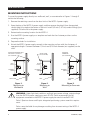
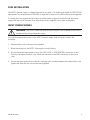
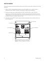
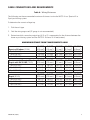
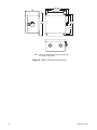
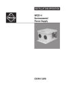
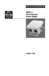
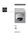
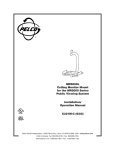
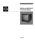
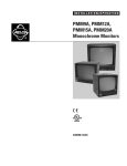
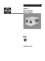
INSTALLATION/OPERATION
®
WCS1-4
Environmental
Power Supply
C561M-D (11/03)
IMPORTANT SAFEGUARDS AND WARNINGS
1. Read these instructions.
2. Keep these instructions.
3. Heed all warnings.
4. Follow all instructions.
5. Installation should be done only by qualified service personnel and conform to all local codes.
6. Use only installation methods and materials capable of supporting four times the maximum
specified load.
7. Do not install near any heat sources such as radiators, heat registers, stoves, or other
apparatus (including amplifiers) that produce heat.
8. Only use attachments/accessories specified by Pelco.
9. Use only with the cart, stand, tripod, bracket, or table specified by Pelco, or sold with the
apparatus. When a cart is used, use caution when moving the cart/apparatus combination to
avoid injury from tip-over.
10. Refer all servicing to qualified service personnel. Servicing is required when the apparatus has
been damaged in any way, such as liquid has been spilled or objects have fallen into the
apparatus, the apparatus does not operate normally, or has been dropped.
11. Only use parts recommended by Pelco.
12. Use stainless steel hardware to fasten the enclosure to outdoor surfaces.
13. AN ALL-POLE MAINS SWITCH with a contact separation of at least 3 mm in each pole shall be
incorporated in the electrical installation of the building (permanent 230 VAC product only).
2
C561M-D (11/03)
DESCRIPTION
The WCS1-4 is a mutliple power supply designed for indoor or outdoor applications and is ideal for
use with cameras, domes, and integrated positioning systems such as Spectra® and Esprit®. The
WCS1-4 is capable of powering up to four units and can handle pan/tilt, heater, blower, and camera
operation.
The WCS1-4 power supply has one fused output and is capable of handling up to 4 amps (100 VA)
of total load. The unit features selectable 100/120/230 VAC input power, selectable 24/26/28 VAC
output power, and a stainless steel link-lock latch that can be secured with padlock (padlock not
provided).
C561M-D (11/03)
3
INSTALLATION
MOUNTING INSTRUCTIONS
To mount the power supply directly to a wallboard, wall, or concrete refer to Figures 1 through 3
and do the following:
1. Remove the retaining screw from the door latch of the WCS1-4 power supply.
2. Open the door of the WCS1-4 power supply, and then remove the plug(s) from the required
conduit hole(s) located on the bottom of the unit. Install 3/4-inch (1.91 cm) conduit fitting(s) (not
supplied). Close the lid to the power supply.
3. Determine the mounting location for the WCS1-4.
4. Use the WCS1-4 power supply as a template and mark the four fastener positions on the
mounting surface.
5. Prepare the holes for installation.
6. Attach the WCS1-4 power supply securely to the mounting surface with four fasteners of
appropriate length. Fasteners between 1/4-inch and 5/16-inch diameter (not supplied) can be
used.
MOUNTING HARDWARE WITH
ANCHOR OR TOGGLE BOLT
(NOT SUPPLIED)
WOOD SCREW
(NOT SUPPLIED)
DOOR
LATCH
DOOR
LATCH
RETAINING
SCREW
RETAINING
SCREW
WALL
WALLBOARD
Figure 1.
Mounting to
Wallboard
Figure 2.
Mounting to
Wall
MOUNTING
HARDWARE
(NOT SUPPLIED)
DOOR
LATCH
RETAINING
SCREW
CONCRETE
WALL
Figure 3.
Mounting to Concrete
WARNING: Under light load conditions and high input power voltage, output voltage
from the WCS1-4 power supply may reach 32 VAC. Pelco recommends that all
equipment connected to the WCS1-4 power supply be rated to handle 32 VAC.
Pelco’s Spectra® domes and Esprit® integrated positioning systems meet this requirement.
Pelco cannot be liable for any damages resulting from incorrect wiring of the WCS1-4
power supply.
4
C561M-D (11/03)
FUSE INSTALLATION
The WCS1-4 power supply is shipped from the factory with a 1.6-amp fuse installed for 100/120 VAC
input power. To use input power of 230 VAC, change the 1.6-amp fuse to a 500-milliamp fuse (supplied).
To change the fuse remove the lid to the fuse holder (refer to figure 4) located inside the power
supply and then install the new fuse. Store extra fuses (supplied) in the spare fuse holders.
INPUT POWER WIRING
WARNING: The WCS1-4 does not have an on/off switch. Turn off power at the circuit
breaker before wiring the power supply.
To install the input power wires to the WCS1-4 power supply, refer to Figure 4 and do the
following:
1. Determine the size of the input wire needed.
2. Bring the wiring into the WCS1-4 through the conduit fitting.
3. Attach the neutral input power wire to the 100V, 120V, or 230V NEUTRAL connection on the
Primary Line Input connector strip. Attach the hot wire to the LINE connection on the same
strip.
4. Attach the input ground wire to the No. 6 ground stud, located between the conduit holes, and
tighten the wire with the nut and washer (supplied).
C561M-D (11/03)
5
OUTPUT WIRING
To install the output wiring to the camera, dome, or positioning system, refer to Figure 4 and do the
following:
1. Refer to Table A and determine the output connection needed for your camera, dome, or
positioning system. Refer to Figure 4, for the proper connector strip connections.
2. Attach one output wire to either the Tap A (24 VAC), Tap B (26 VAC), or Tap C (28 VAC)
connections on the Secondary Output Tap’s connector strip and attach the second wire to the
COM connection on the same strip. Be sure that you have the proper wiring size and distances
installed if you plan to change connections later.
3. Close the lid to the WCS1-4 power supply, replace the retaining screw to the door latch, and
then turn power on.
SPARE FUSES
FUSE HOLDER
120V-1.6A, 250V
220V-0.5A, 250V
OUTPUT TERMINALS
GROUND STUD
Line
Neutral
100V
120V
230V
Primary Line Input
COM
INPUT TERMINALS
A
B
C
Secondary Output Taps
Figure 4. Wiring Connector Diagram
6
C561M-D (11/03)
CABLE CONNECTIONS AND REQUIREMENTS
Table A. Wiring Distances
The following are the recommended maximum distances to wire the WCS1-4 to a Spectra III or
Esprit positioning system.
To determine the correct voltage tap:
1. Pick the unit type.
2. Find the wire gauge used (22 gauge is not recommended).
3. Determine which secondary output tap (A, B, or C) is appropriate for the distance between the
dome or positioning system and the WCS1-4. Distance is in feet (meters).
MAXIMUM DISTANCE FROM TRANSFORMER TO LOAD
Spectra III Indoor (25 VA)
Tap A (24 VAC)
Tap B (26 VAC)
Tap C (28 VAC)
20 AWG
(0.5 mm2)
113 (34)
133 (40)
155 (47)
18 AWG
(1.0 mm2)
180 (55)
212 (64)
246 (75)
16 AWG
(1.5 mm2)
287 (87)
337 (103)
392 (119)
14 AWG
(2.5 mm2)
455 (139)
536 (163)
623 (190)
12 AWG
(4.0 mm2)
725 (221)
852 (260)
990 (302)
Environmental Spectra III and
Esprit with IOC & IOP (70 VA)
Tap A (24 VAC)
Tap B (26 VAC)
Tap C (28 VAC)
20 AWG
(0.5 mm2)
41 (12)
49 (15)
55 (17)
18 AWG
(1.0 mm2)
64 (19)
78 (24)
88 (27)
16 AWG
(1.5 mm2)
102 (31)
124 (38)
135 (41)
14 AWG
(2.5 mm2)
163 (50)
198 (60)
222 (68)
12 AWG
(4.0 mm2)
259 (79)
315 (96)
353 (107)
Esprit (50 VA)
Tap A (24 VAC)
Tap B (26 VAC)
Tap C (28 VAC)
20 AWG
(0.5 mm2)
56 (17)
66 (20)
77 (23)
18 AWG
(1.0 mm2)
90 (27)
105 (32)
122 (37)
16 AWG
(1.5 mm2)
143 (43)
168 (51)
195 (59)
14 AWG
(2.5 mm2)
228 (69)
268 (81)
311 (94)
12 AWG
(4.0 mm2)
362 (110)
425 (129)
493 (150)
C561M-D (11/03)
7
MAINTENANCE
There are no user-serviceable parts except for the fuse. If the transformer in the WCS1-4 does not
work properly, the entire environmental power supply needs to be returned to the factory for repair.
Refer to the Warranty and Return Information for instructions on returning the WCS1-4.
Clean the outer surface of the WCS1-4 box with a nonabrasive cleaning cloth and antistatic
cleaner. Do not use kerosene or similar substances that may damage the surface.
8
C561M-D (11/03)
SPECIFICATIONS
ELECTRICAL
Input Voltage:
Output
Voltage/Power:
Fusing:
Spare Fuse
Holder:
Selectable 100, 120, 230 VAC, 50/60 Hz via the Primary Line Input connector
strip
Selectable 24 VAC (Tap A), 26 VAC (Tap B), or 28 VAC (Tap C) at 100 VA via
the Secondary Output Tap’s connector strip
One fuse. Select from one of the following supplied fuses:
Three 1.6 A fast-acting fuses (100 VAC or 120 VAC)
Three 500 mA fast-acting fuses (230 VAC)
Two spare fuse holders (attached to transformer cover)
MECHANICAL
Construction:
Aluminum
Finish:
Gray polyester powder coat
Cable Entry:
Two hole plugs will accommodate 3/4-inch (1.91 cm) conduit fittings (not
provided) that meet NEMA Type 4X standards.
Mount Method:
Four 0.375-inch (0.95 cm) holes on mounting plate
Latch:
One stainless steel link-lock latch secured with screw; latch also can be
secured with padlock (not supplied)
GENERAL
Environment:
Indoor/outdoor
Operating Range:
-50°F to 122°F (-45.56°C to 50°C)
Weight:
6.5 lb (2.95 kg)
Dimensions:
See Figure 5
(Design and product specifications subject to change without notice.)
C561M-D (11/03)
9
6.50 (16.51)
5.63 (14.30)
4.50 (11.43)
4.00
(10.16)
7.88
(20.02)
6.44
(16.36)
5.88
(14.94)
NOTE: VALUES IN PARENTHESES ARE CENTIMETERS;
ALL OTHERS ARE INCHES.
Figure 5. WCS1-4 Dimension Drawing
10
C561M-D (11/03)
WARRANTY AND RETURN INFORMATION
WARRANTY
Pelco will repair or replace, without charge, any merchandise proved defective in material or workmanship for a period of one year after the date of
shipment. Exceptions to this warranty are as noted below:
•
•
•
•
•
•
•
•
•
•
Five years on Pelco manufactured cameras (CC3500/CC3600/CC3700 and MC3500/MC3600 Series); two years on all other cameras.
Three years on Genex® Series (multiplexers, server, and keyboard) and 090 Series Camclosure® Camera System.
Two years on 100/150, 200 and 300 Series Camclosure® Camera Systems.
Two years on all standard motorized or fixed focal length lenses.
Two years on Legacy®, CM6700/CM6800/CM8500/CM9500/CM9740/CM9760 Matrix, DF5 and DF8 Series Fixed Dome products.
Two years on Spectra®, Esprit®, and PS20 Scanners, including when used in continuous motion applications.
Two years on Esprit and WW5700 series window wiper (excluding wiper blades).
Eighteen months on DX Series digital video recorders.
One year (except video heads) on video cassette recorders (VCRs). Video heads will be covered for a period of six months.
Six months on all pan and tilts, scanners or preset lenses used in continuous motion applications (that is, preset scan, tour and auto scan modes).
Pelco will warrant all replacement parts and repairs for 90 days from the date of Pelco shipment. All goods requiring warranty repair shall be sent
freight prepaid to Pelco, Clovis, California. Repairs made necessary by reason of misuse, alteration, normal wear, or accident are not covered under
this warranty.
Pelco assumes no risk and shall be subject to no liability for damages or loss resulting from the specific use or application made of the Products.
Pelco’s liability for any claim, whether based on breach of contract, negligence, infringement of any rights of any party or product liability, relating to
the Products shall not exceed the price paid by the Dealer to Pelco for such Products. In no event will Pelco be liable for any special, incidental or
consequential damages (including loss of use, loss of profit and claims of third parties) however caused, whether by the negligence of Pelco or
otherwise.
The above warranty provides the Dealer with specific legal rights. The Dealer may also have additional rights, which are subject to variation from
state to state.
If a warranty repair is required, the Dealer must contact Pelco at (800) 289-9100 or (559) 292-1981 to obtain a Repair Authorization number (RA), and
provide the following information:
1. Model and serial number
2. Date of shipment, P.O. number, Sales Order number, or Pelco invoice number
3. Details of the defect or problem
If there is a dispute regarding the warranty of a product which does not fall under the warranty conditions stated above, please include a written
explanation with the product when returned.
Method of return shipment shall be the same or equal to the method by which the item was received by Pelco.
RETURNS
In order to expedite parts returned to the factory for repair or credit, please call the factory at (800) 289-9100 or (559) 292-1981 to obtain an
authorization number (CA number if returned for credit, and RA number if returned for repair).
All merchandise returned for credit may be subject to a 20% restocking and refurbishing charge.
Goods returned for repair or credit should be clearly identified with the assigned CA or RA number and freight should be prepaid. Ship to the
appropriate address below.
If you are located within the continental U.S., Alaska, Hawaii or
Puerto Rico:
Service Department
Pelco
3500 Pelco Way
Clovis, CA 93612-5699
If you are located outside the continental U.S., Alaska, Hawaii or Puerto Rico:
Intermediate Consignee
Ultimate Consignee
American Overseas Air Freight
Pelco
320 Beach Road
3500 Pelco Way
Burlingame, CA 94010
Clovis, CA 93612-5699
USA
USA
® Pelco, the Pelco logo, Spectra, Genex, Coaxitron, Legacy, Esprit, Camclosure, Spectra III, and Spectra III SE are registered trademarks of Pelco.
© Copyright 2003, Pelco. All rights reserved.
REVISION HISTORY
Manual #
C561M
C561M-A
C561M-B
C561M-C
Date
11/97
12/98
5/00
6/00
5/03
C561M-D
11/03
C561M-D (11/03)
Comments
Original version.
Changed model number. Revised Table A to update vA ratings for Spectra.
Changed model number.
Revised manual to support changes required for UL listing.
Revised Wiring Distance section to include Spectra III and Esprit information. Updated manual to
new format.
Revised cover photo and Figure 5 to show new conduit hole plug per ECO #01-6947.
11
®
World Headquarters
3500 Pelco Way
Clovis, California 93612 USA
USA & Canada
Tel: 800/289-9100
Fax: 800/289-9150
International
Tel: 1-559/292-1981
Fax: 1-559/348-1120
www.pelco.com
ISO9001
Orangeburg, New York Las Vegas, Nevada Eindhoven, The Netherlands Wokingham, United Kingdom Montreal, Canada
Singapore