1
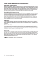
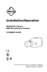
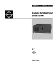
®
Installation/Operation
CC3751H-2
DSP Color Camera
C1988M-B (4/03)
Pelco World Headquarters • 3500 Pelco Way, Clovis, CA 93612-5699 USA • www.pelco.com
USA & Canada: Tel: 800/289-9100 • Fax: 800/289-9150
International: Tel: 1-559/292-1981 • Fax: 1-559/348-1120
IMPORTANT SAFEGUARDS AND WARNINGS
Prior to installation and use of this product, the following WARNINGS should be observed.
1. Installation and servicing should be done only by qualified service and installation personnel.
2. Installation shall be done in accordance with all local and national electrical and mechanical codes
utilizing only approved materials.
3. Use only installation methods and materials capable of supporting four times the maximum specified
load.
4. Use only UL listed class 2 power supply.
5. To prevent fire or shock hazard, do not expose this appliance to rain or moisture.
REGULATORY NOTICES
This equipment has been tested and found to comply with the limits of a Class B digital device, pursuant
to part 15 of the FCC rules. These limits are designed to provide reasonable protection against harmful
interference in a residential installation. This equipment generates, uses, and can radiate radio frequency
energy and, if not installed and used in accordance with the instructions, may cause harmful interference
to radio communications. However there is no guarantee that the interference will not occur in a particular
installation. If this equipment does cause harmful interference to radio or television reception, which can
be determined by turning the equipment off and on, the user is encouraged to try and correct the interference by one or more of the following measures:
•
•
•
•
Reorient or relocate the receiving antenna.
Increase the separation between the equipment and the receiver.
Connect the equipment into an outlet on a circuit different from that to which the receiver is connected.
Consult the dealer or an experienced radio/TV technician for help.
DESCRIPTION
The CC3751H-2 is a high resolution, color video camera with a 1/3-inch CCD imager. The camera features
a digital slow shutter (DSS) mode, a direct drive/auto iris lens connector, adjustable back focus, backlight
compensation, automatic gain control, and an adjustable C/CS lens mount.
Models
CC3751H-2
[2]
High resolution, 480 TV lines, HyperHAD™ CCD, minimum illumination of 0.017 lux at
f1.2 and 50 IRE, NTSC format
Pelco Manual C1988M-B (4/03)
CAMERA LAYOUT
BACK FOCUS
ADJUSTMENT
MOUNT ADAPTER
LOCKING
SCREW
PHASE ADJUSTMENT
LENS LEVEL ADJUSTMENT
POWER CONNECTOR
COSMETIC TRIM
RING
BACK FOCUS
ADJUSTMENT
RING
BNC VIDEO CONNECTOR
LED
LENS CONNECTOR
20156
DIP SWITCHES
(COVER REMOVED)
NOTE: The cosmetic
trim ring conceals the
LED light for more
discreet surveillance
operations. The trim
ring also hides the
power connectors and
protects the DIP
switches.
Figure 1. Camera Layout
INSTALLATION
Lens Mounting
The camera can use a fixed iris, manual iris, or auto iris lens. The camera is factory set for a CS-mount
lens, but is easily adjusted for a C-mount lens.
1. C-Mount Lens Only - Rotate the back focus adjustment fully counterclockwise before installing the C-mount lens (refer to the section on Back Focus Adjustment ).
2. Remove the cosmetic trim ring from the back of the camera (refer to Figure 1). Set the lens mode selector switch on the side of the camera to AIV (auto iris video drive lens) or AID (auto iris DC drive
lens). Refer to the Switch Settings section. Switch setting is determined by the type of lens used.
3. Screw the lens onto the lens mount. Be careful to prevent dust from entering the space between the
lens and the CCD element. If necessary, use clean, compressed air to remove any foreign matter.
4. Thread the lens cable through the cosmetic trim ring.
5. Connect the auto iris lens to the four-pin connector located on the side of the camera. Pin connections for the iris drive connector are as follows:
3
4
1
2
PIN
1
2
3
4
DC AUTO IRIS LENS
Control coil negative (-)
Control coil positive (+)
Drive coil positive (+)
Drive coil negative (-)
VIDEO AUTO IRIS LENS
Lens positive supply
Not used
Video drive signal
Ground
Figure 2. Lens Connections
Pelco Manual C1988M-B (4/03)
[3]
Camera Mounting
Use a standard 1/4-20 screw (provided) with a maximum thread length of 3/8-inch (10 mm) for top or bottom camera mounting. The mount adapter may be fitted to the top or bottom of the camera. The camera
is shipped with the mount adapter located on the top of the camera.
1
To change the mount adapter position:
2
Remove the four screws from the mount adapter located
on the top of the camera.
Remove the trim cover from the bottom of the camera by
prying it loose. Place the trim cover on the top of the camera where the mount adapter was removed. Press into
place.
Install the mount adapter to the bottom of the camera. Secure with the four screws removed in step 1.
3
Figure 3. Camera Mounting
Power and Video Connections
The camera is designed to operate from a 12 VDC or 24 VAC power supply. The power supply connections are shown in Figure 4. The LED on the back panel of the camera indicates that power is connected.
Use only a Class 2 isolated power supply. See Specifications for power consumption.
CLASS 2
ISOLATED
POWER
SUPPLY
CLASS 2
ISOLATED
POWER
SUPPLY
24 VAC
12 VDC
20155
Figure 4. Power Supply Connections
To connect the camera power and video:
1. Remove the cosmetic trim ring from the camera (refer to Figure 1). Thread cabling through the rear cover.
2. Connect the power cable to the two-pin power connector on the back of the camera using the terminal
block connector (provided). Refer to Table A for the recommended wire gauge and wiring distances.
3. Connect a video cable to the SIGNAL OUT connector (BNC) on the back of the camera. Refer to
Table B for the type of video coaxial cable to use.
4. Reattach the cosmetic trim ring to the back of the camera.
[4]
Pelco Manual C1988M-B (4/03)
AC Operation Only - If you are wiring more than one camera to the same transformer, connect one side of
the transformer to the same terminal on all cameras, and connect the other side of the transformer to the remaining terminal on all cameras. Failure to connect all of the cameras the same way will cause the cameras
to be out of phase with each other and may produce a vertical roll when switching between cameras.
Table A. Recommended Wire Gauge and Wiring Distances
The following are the recommended maximum distances for 24 VAC applications and are calculated with a 10percent voltage drop. (Ten percent is generally the maximum allowable voltage drop for AC-powered devices.)
Wire Gauge
Total
VA
10
20
(0.5 mm2)
283
(86)
18
(1.0 mm2)
451
(137)
16
(1.5 mm2)
716
(218)
14
(2.5 mm2)
1142
(348)
12
(4.0 mm2)
1811
(551)
10
(6.0 mm2)
2880
(877)
Example: A camera that requires 10 VA and is installed 283 feet (86 m) from the transformer would
require a minimum wire gauge of 20 AWG.
NOTE: Wire gauges are standard AWG or metric sizes. Distances are calculated in feet; values in parentheses are meters.
Table B. Video Coaxial Cable Requirements
Cable Type*
RG59/U
RG6/U
RG11/U
Maximum Distance
750 ft (229 m)
1,000 ft (305 m)
1,500 ft (457 m)
* Minimum cable requirements:
75 ohms impedance
All-copper center conductor
All-copper braided shield with 95% braid coverage
Pelco Manual C1988M-B (4/03)
[5]
LENS SETUP AND FOCUS PROCEDURES
Video Drive Auto Iris Lens
Set the lens mode selector switch to AIV. Switch the ESC OFF. Refer to the lens instructions and adjust the
lens for the optimum picture (video output level of 1V peak-to-peak). To focus, fully open the iris by covering
the lens with a suitable neutral density (ND*) filter. If the viewed scene is 6.5 feet (2 m) away or farther, set
the lens focus to infinity (far). Use the back focus adjustment ring (refer to the Back Focus Adjustment section) to focus on the selected scene. Remove the ND filter and set the lens focus as required.
Direct Drive (DC) Auto Iris Lens
Set the lens mode selector switch to AID. Switch the ESC ON. Use an appropriate screwdriver to turn the
lens level potentiometer (refer to Figure 1) fully clockwise. Next, slowly adjust the potentiometer counterclockwise until the optimum picture is obtained (video output level of 1V peak-to-peak). To focus, fully
open the iris by covering the lens with a suitable neutral density (ND*) filter. Select the scene to be
viewed. If the viewed scene is 6.5 feet (2 m) away or farther, set the lens focus to infinity (far). Use the
back focus adjustment ring (refer to the Back Focus Adjustment section) to focus on the selected scene.
Remove the ND filter and set the lens focus as required.
Fixed Lens
To focus, set the lens focus to infinity and view an image greater than 6.5 feet (2 m) away. Focus the image with the back focus adjustment ring (refer to the Back Focus Adjustment section). Set the lens focus
as required.
Manual Iris Lens
To focus, open the iris fully and set the lens focus to infinity. View an image greater than 6.5 feet (2 m)
away. Focus the image with the back focus adjustment ring (refer to the Back Focus Adjustment section).
Adjust the lens focus, and set the iris for the best picture quality. The largest aperture gives the best light
sensitivity, the smallest aperture the greatest depth of field.
Zoom Lens
Set the lens focus to infinity (far) and fully open the iris by covering the lens with a suitable neutral density
(ND*) filter. Zoom out to the widest field of vision and view a distant object. Adjust the back focus adjustment ring until the object is in focus (refer to the Back Focus Adjustment section). Next, zoom fully in and
adjust the lens focus until the object is again focused. Repeat these steps until the full zoom range may
be viewed with the minimum loss of focus.
* NOTE: For best results, outdoors, use an ND3 filter.
[6]
Pelco Manual C1988M-B (4/03)
BACK FOCUS ADJUSTMENT
The back focus adjustment is located at the front of the camera and is accessible from either side of the
case.
To adjust the back focus:
1. Loosen the two back focus locking screws (one on each side).
2. Turn the back focus ring until the object is in focus.
3. When the back focus adjustment is satisfactory, tighten the locking screws. Do not over tighten the
locking screw or force the back focus adjustment ring.
ISE
KW
OC
RCL
TE
UN
CO
BACK FOCUS
ADJUSTMENT
RING
BACK FOCUS
ADJUSTMENT
LOCKING SCREW
ISE
CKW
CLO
Figure 5. Back Focus Adjustment
Pelco Manual C1988M-B (4/03)
[7]
SWITCH SETTINGS
-
+
PHASE
H
LEVEL
ON
OFF
OFF
L
BLC
OPT
1
3
AW1
ESC
AW2
AIV
AID
5
INT
LL
OFF
NOR
2
4
Note: White indicates
switch setting.
6
7
OFF
SHP
LC
OFF
DS1
9
OFF
DS2
8
10
00152
Figure 6. DIP Switch Default Settings
BLC - Backlight Compensation
OFF (Default setting) - Disables the BLC mode.
BLC - Enables the BLC mode. If a bright backlight is present, the subjects in the picture may appear
dark or as a silhouette. BLC enhances objects in the center of the picture.
OPT - Optimal Video
OFF (Default setting)
OPT - Boosts the video by 3 dB.
ESC - Electronic Shutter Control
OFF - Disables the ESC mode.
ESC (Default setting) - Enables the ESC mode. The ESC function automatically changes the sensitivity of the camera by varying the electronic shutter speed according to the amount of incident light.
Electronic shutter speed range is 1/60 to 1/100,000.
AW1/AW2 - Automatic White Balance
AW1 (Default setting) - Automatically processes the viewed image to retain color balance over a
wide color temperature range.
AW2 - Processes the viewed image to retain color balance in a restricted color temperature range.
AIV/AID - Auto Iris Lens Mode Selector
The switch setting is determined by the type of lens used:
AIV - Video-controlled auto iris lens.
AID (Default setting) - DC-controlled auto iris lens.
INT/LL - Internal/Line Lock
Line Lock (LL) (Default setting) - Locks the frame rate to the power supply frequency. Eliminates
vertical roll caused by multiple cameras connected to the same switching device.
Internal - Locks the frame rate to the internal oscillator. Use with DC or unstable AC.
NOR/SHP - Sharpness
NOR (Default setting) - Sets the camera to normal sharpness mode.
SHP - Enables the Sharpness mode. Enhances picture detail by increasing the aperture gain of the
camera, sharpening the edges in the picture.
[8]
Pelco Manual C1988M-B (4/03)
LC - Long Line Compensation
OFF (Default setting) - Disables the Long Line Compensation mode.
LC - Enables the Long Line Compensation mode. Boosts the video drive level to 1.25 Vp-p for long
line transmission.
DS1 and DS2 - Digital Slow Shutter
Digital slow shutter slows the picture frame rate and increases the camera sensitivity under low light
conditions. Depending on the number of fields of integration, the picture will develop a granular appearance and motion may show some lag, resulting in a stereoscopic effect or streaking on fast-moving
objects. These effects increase as the number of fields of integration increases.
For the DSS mode to operate correctly, set the OPT switch to OFF. The camera has four DSS settings:
9 OFF
DS1
10 OFF
DS2
9 OFF
DS1
10 OFF
DS2
9 OFF
DS1
10 OFF
DS2
9 OFF
DS1
10 OFF
DS2
OFF - Disables the DSS mode.
4 Fields of Integration Maximum - 1/15-second scene update rate.
16 Fields of Integration Maximum - 1/4-second scene update rate.
30 Fields of Integration Maximum (Default setting) - 1/2-second scene
update rate.
00028
NOTE: White represents switch postion.
Digital slow shutter automatically adjusts the number of fields of integration depending on the light
level of the viewed scene, up to the maximum determined by the settings of switches (9) and (10).
Pelco Manual C1988M-B (4/03)
[9]
CAMERA SYNCHRONIZATION (AC OPERATION ONLY)
When using more than one camera power supply, a brief vertical roll may occur on the monitor when a
camera view is switched. To eliminate vertical roll, adjust the phase control by synchronizing, or line-locking, the cameras to one another. Use the phase potentiometer located on the side of the camera (refer to
Figure 1) to make adjustments.
It may be necessary to have two people in communication when synchronizing the cameras: one person
at the camera and another person at the monitor to observe the vertical roll and the effect of any adjustments made at the camera.
To synchronize the cameras do the following:
1. Choose a reference camera to which all other cameras will be phased.
2. Select a camera and synchronize it to the reference camera by turning the phase adjustment control
clockwise and/or counterclockwise.
3. Each time an adjustment is made, switch back and forth between the camera you are adjusting and
the reference camera. Repeat this process as many times as necessary, until the roll between the
cameras is no longer noticeable.
4. Adjust the phase of all other cameras by repeating steps 2 through 3. Always adjust to the reference
camera selected in step 1.
NOTE: The preferred method for camera phase adjustment is to use a dual trace oscilloscope to align
the vertical sync pulses of the reference camera to the selected camera(s).
[ 10 ]
Pelco Manual C1988M-B (4/03)
SPECIFICATIONS
GENERAL
CCD Sensor:
Picture Elements:
Sensing Area:
Synchronization System:
Horizontal Resolution:
Iris Control:
Minimum Illumination:
ESC:
Signal-to-Noise Ratio:
Gain Control:
Vertical Phase:
Backlight Compensation:
Scanning System:
Signal Processing:
Auto Iris Lens Type:
Video Output:
ELECTRICAL
Power Requirements
24 VAC:
12 VDC:
Power Consumption:
1/3-inch interline transfer
768 (H) x 494 (V)
6 mm diagonally
INT/AC line lock
480 TV lines
Electronic/passive
0.013 lux at f1.2, 50 IRE
0.008 lux at f1.2, 35 IRE
1/60-1/100,000 second
50 dB (AGC off)
Automatic
Adjustable 340° range
Selectable by DIP switch setting
525 lines, 2:1 interlace
DSP with microprocessor control
DC/video control, selectable by DIP switch setting
1 Vp-p, 75 ohms
1.2 Vp-p for long line transmission
Power Connector:
Video Connector:
Lens Jack:
18-30 VAC
10-36 VDC
3.3 watts maximum
5.4 VA maximum
2-pin terminal strip, push-in type
BNC
4-pin connector (miniature square with screw lock)
MECHANICAL
Lens Mount
Camera Mount
C/CS mount (adjustable)
Use 1/4-20 screw, top or bottom of camera housing
ENVIRONMENTAL
Operating Temperature:
Storage Temperature:
14° to 122°F (-10° to 50°C)
14° to 158°F (-10° to 70°C)
PHYSICAL
Dimensions:
Weight (without lens):
2.48 (W) x 2.67 (H) x 4.33 (D) inches (6.3 x 6.8 x 11 cm)
0.77 lb (0.35 kg)
(Design and product specifications subject to change without notice.)
Pelco Manual C1988M-B (4/03)
[ 11 ]
WARRANTY AND RETURN INFORMATION
WARRANTY
Pelco will repair or replace, without charge, any merchandise proved defective in material or workmanship for a period of one year after the
date of shipment. Exceptions to this warranty are as noted below:
•
•
•
•
•
•
•
•
•
•
Five years on Pelco manufactured cameras (CC3500/CC3600/CC3700 and MC3500/MC3600 Series); two years on all other cameras.
Three years on Genex® Series (multiplexers, server, and keyboard) and 090 Series Camclosure® Camera System.
Two years on 100/150, 200, and 300 Series Camclosure Camera Systems.
Two years on all standard motorized or fixed focal length lenses.
Two years on Legacy®, CM6700/CM6800/CM6800E/CM8500/CM9500/CM9740/CM9760 Matrix, DF5 and DF8 Series Fixed Dome
products.
Two years on Spectra®, Esprit®, and PS20 Scanners, including when used in continuous motion applications.
Two years on Esprit and WW5700 series window wiper (excluding wiper blades).
Eighteen months on DX Series digital video recorders.
One year (except video heads) on video cassette recorders (VCRs). Video heads will be covered for a period of six months.
Six months on all pan and tilts, scanners or preset lenses used in continuous motion applications (that is, preset scan, tour and auto
scan modes).
Pelco will warrant all replacement parts and repairs for 90 days from the date of Pelco shipment. All goods requiring warranty repair shall be
sent freight prepaid to Pelco, Clovis, California. Repairs made necessary by reason of misuse, alteration, normal wear, or accident are not
covered under this warranty.
Pelco assumes no risk and shall be subject to no liability for damages or loss resulting from the specific use or application made of the
Products. Pelco’s liability for any claim, whether based on breach of contract, negligence, infringement of any rights of any party or product
liability, relating to the Products shall not exceed the price paid by the Dealer to Pelco for such Products. In no event will Pelco be liable for
any special, incidental or consequential damages (including loss of use, loss of profit and claims of third parties) however caused, whether
by the negligence of Pelco or otherwise.
The above warranty provides the Dealer with specific legal rights. The Dealer may also have additional rights, which are subject to variation
from state to state.
If a warranty repair is required, the Dealer must contact Pelco at (800) 289-9100 or (559) 292-1981 to obtain a Repair Authorization number
(RA), and provide the following information:
1. Model and serial number
2. Date of shipment, P.O. number, Sales Order number, or Pelco invoice number
3. Details of the defect or problem
If there is a dispute regarding the warranty of a product which does not fall under the warranty conditions stated above, please include a
written explanation with the product when returned.
Method of return shipment shall be the same or equal to the method by which the item was received by Pelco.
RETURNS
In order to expedite parts returned to the factory for repair or credit, please call the factory at (800) 289-9100 or (559) 292-1981 to obtain an
authorization number (CA number if returned for credit, and RA number if returned for repair).
All merchandise returned for credit may be subject to a 20% restocking and refurbishing charge.
Goods returned for repair or credit should be clearly identified with the assigned CA or RA number and freight should be prepaid. Ship to the
appropriate address below.
If you are located within the continental U.S., Alaska, Hawaii or
Puerto Rico:
Service Department
Pelco
3500 Pelco Way
Clovis, CA 93612-5699
If you are located outside the continental U.S., Alaska, Hawaii or
Puerto Rico:
Intermediate Consignee
Ultimate Consignee
American Overseas Air Freight
Pelco
320 Beach Road
3500 Pelco Way
Burlingame, CA 94010
Clovis, CA 93612-5699
USA
USA
® Pelco, the Pelco logo, Spectra, Genex, Legacy, Esprit, and Camclosure are registered trademarks of Pelco.
™ HyperHAD and EXviewHAD are trademarks of Sony Corporation.
© Copyright 2003, Pelco. All rights reserved.
REVISION HISTORY
Manual #
C1988M
C1988M-A
C1988M-B
[ 12 ]
Date
5/02
6/02
4/03
Comments
Original version.
Revised the lens connector wiring chart.
Added S-mark certification.
Pelco Manual C1988M-B (4/03)