1
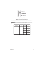
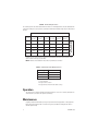
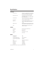
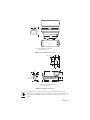
I N S T A L L A T I O N
EU3512-3X
Environmental
Enclosure and Light
Duty Wall Mount
C2428M-B (1/06)
Important Safety Instructions
Prior to installation and use of this product, the following WARNINGS should be observed.
1. Read these instructions.
2. Keep these instructions.
3. Heed all warnings.
4. Follow all instructions.
5. Only use attachments/accessories specified by the manufacturer.
6. Use only with the cart, stand, tripod, bracket, or table specified by the manufacturer, or sold
with the apparatus. When a cart is used, use caution when moving the cart/apparatus
combination to avoid injury from tip-over.
7. Refer all servicing to qualified service personnel. Servicing is required when the apparatus
has been damaged in any way, such as power-supply cord or plug is damaged, liquid has been
spilled or objects have fallen into the apparatus, the apparatus has been exposed to rain or
moisture, does not operate normally, or has been dropped.
8. Installation should be done only by qualified personnel and conform to all local codes.
9. Unless the unit is specifically marked as a NEMA Type 3, 3R, 3S, 4, 4X, 6, or 6P enclosure, it is
designed for indoor use only and it must not be installed where exposed to rain and moisture.
10. Use only installation methods and materials capable of supporting four times the maximum
specified load.
11. Use stainless steel hardware to fasten the mount to outdoor surfaces.
12. AN ALL POLE MAINS SWITCH with a contact separation of at least 3 mm in each pole shall be
incorporated in the electrical installation of the building.
13. Only use replacement parts recommended by Pelco.
14. CAUTION: These servicing instructions are for use by qualified service personnel only.
To reduce the risk of electric shock, do not perform any servicing other than contained in the
operating instructions unless you are qualified to do so.
The product and/or manual may bear the following marks:
This symbol indicates that
dangerous voltage constituting
a risk of electric shock is present
within this unit.
This symbol indicates that there
are important operating and
maintenance instructions in the
literature accompanying this
unit.
CAUTION:
RISK OF ELECTRIC SHOCK.
DO NOT OPEN.
Please thoroughly familiarize yourself with the information in this manual prior to installation and
operation.
C2428M-B (1/06)
3
Description
The EU3512-3X is an indoor/outdoor light-duty camera enclosure and light-duty wall mount. The
enclosure includes a sun shroud and 230 VAC heater and defroster. The wall mount has an adjustable
tilt table allowing for mechanical positioning of the enclosure.
Install the EU3512-3X to any wall or vertical surface capable of supporting up to 20 lbs (9 kg).
4
C2428M-B (1/06)
Installation
INSTALL WALL MOUNT
1. Drill holes in mounting surface using the mount as a template and attach the mount securely
with the recommended fasteners.
•
•
If you are attaching the mount to a solid surface, use the two top outside holes and the
bottom center hole. Secure with three 0.25-inch diameter fasteners (not supplied).
If you are attaching the mount to a wall stud, use the top and bottom center fastener
holes. Secure with one 0.3125-inch fastener and one 0.25-inch fastener (not supplied).
2. If you install the mount outdoors, seal the fastener holes with an appropriate sealant to
prevent water damage. Apply the sealant between the mount and the mounting surface.
ENCLOSURE INSTALLATION
The following items are supplied to mount the enclosure:
2 1/4-20 x 0.500-inch hex head screws
2 Flat washers
2 Split washers
The following items are supplied to mount the camera:
2 1/4-20 x 0.375-inch Phillips screws
Perform the following steps to install the enclosure:
1. Unlatch and open the lid of the enclosure.
2. Remove the camera sled from the rail of the enclosure.
a.
Loosen the screws that hold the camera sled in place.
b.
Slide the sled forward so it can be lifted out over the screws.
c.
Remove the sled.
d.
Remove the parts bag tied to the sled. This includes the hex head screws, flat washers,
split washers, glands, and nuts.
3. If you are wiring the enclosure with cable, remove the glands and nuts from the parts bag and
install them in the bottom of the enclosure. If you are wiring the enclosure with conduit, do
not install the glands.
4. Attach the base of the enclosure to the mount tilt table through the two threaded mounting
holes in the bottom of the enclosure. Use the 1/4-20 x 0.500-inch screws, the split washers,
and the flat washers provided (in the parts bag). Completely tighten the screws to attach the
enclosure to the mount tilt table.
5. Loosen the cap nut located on the support bracket of the tilt table and adjust the tilt table to
the desired direction. Tighten the cap nut. Loosen the two screws on the tilt table and adjust it
for the desired angle. Tighten the screws.
C2428M-B (1/06)
5
CAMERA AND LENS INSTALLATION
1. To install the camera and lens onto the enclosure sled:
a.
Extend the lens to the maximum length.
b.
Position the camera and lens so that they do not extend beyond the track.
c.
Fasten the camera and lens to the sled with the two, 1/4-20 x 0.375 Phillips screws
(supplied).
The edges of the sled are bent, one side up and the other side down. One side of the sled has
a wide lip and the other side has a narrow lip. In a typical installation, you mount the camera
so that the holes in the wide lip of the sled fit over the sled mounting screws. However, you can
elevate the sled if you are installing a camera with a low optical centerline or a camera with a
large diameter lens. To elevate the sled, flip the sled over so that the holes in the narrow lip of
the sled fit over the sled mounting screws.
2. Install the sled and camera assembly into the enclosure. Slide the sled over the mounting
screws and lightly tighten the screws.
3. Pull the power wires and cables through the glands or conduit into the enclosure. Refer to
Tables A and B to determine the size of the power wire to use. Refer to Table C for the type of
video coaxial cable to use.
NOTE: Be sure to route wiring to maintain separation between 120/230 VAC, 24 VAC, and video
wiring.
4. Connect the cables for power and video to the camera.
5. You will need to access the PC board to wire the heater and defroster to power. To remove the
cover, insert a screwdriver into the slot on top of the cover and lift the cover off.
To connect the heater and defroster to power, refer to Figure 1 for wiring information. Connect
ground to the stud on the bottom of the enclosure just in front of the PC board.
Replace the PC board cover, making sure it snaps securely back into place.
6. If the camera lens is adjustable, extend the lens to its maximum length; verify that the end of
the lens is a minimum of 0.500-inch from the enclosure window.
7. Tighten the screws that secure the sled to the enclosure.
8. Adjust the glands for a tight fit around the cables.
9. Close the enclosure lid, and latch.
10. Adjust the camera focus and iris if necessary. If you need to adjust the focus and iris manually,
open the enclosure lid, adjust the focus and iris, and close the enclosure lid.
6
C2428M-B (1/06)
INPUT, AC HIGH
INPUT, AC LOW (NEUTRAL)
1
2
3
4
5
6
7
8
9
10
DEFROSTER
HEATER
Figure 1. Wiring Diagram
Table A. Heater and Defroster Wiring Distances
The following cable sizes are the minimum recommended for use with the heater and defroster.
WARNING: When using a single power source for both camera and accessories, consider
the camera power consumption when determining the wire gauge.
C2428M-B (1/06)
Input Voltage
Power
Consumption
230 VAC at 50 Hz
43 watts
Cable Size
Cable
Distance
20 AWG
(0.5 mm2)
6,473 ft
(1,973 m)
18 AWG
(1.0 mm2)
10,291 ft
(2,137 m)
16 AWG
(1.5 mm2)
16,365 ft
(4,988 m)
14 AWG
(2.5 mm2)
26,019 ft
(7,931 m)
7
Table B. 24 VAC Wiring Distances
The following are the recommended maximum distances for 24 VAC applications and are calculated with
a 10 percent voltage drop. (Ten percent is generally the maximum allowable voltage drop for AC-powered
devices.)
Wire Gauge
Total VA
20 AWG
(0.5 mm2)
18 AWG
(1.0 mm2)
16 AWG
(1.5 mm2)
14 AWG
(2.5 mm2)
10
283 (86)
451 (137
716 (218)
1142 (348) 1811 (551) 2880 (877)
20
141 (42)
225 (68)
358 (109)
571 (174)
905 (275)
1440 (438)
30
94 (28)
150 (45)
238 (72)
380 (115)
603 (183)
960 (292)
40
70 (21)
112 (34)
179 (54)
285 (86)
452 (137)
720 (219)
50
56 (17)
90 (27)
143 (43)
228 (69)
362 (110)
576 (175)
10 AWG
(6.0 mm2)
Maximum distance from
transformer to load
12 AWG
(4.0 mm2)
Example: An enclosure that requires 30 VA and is installed 94 feet (28 m) from the transformer would
require a minimum wire gauge of 20 AWG.
NOTE: Distances are calculated in feet; values in parentheses are meters.
Table C. Video Coaxial Cable Wiring Distances
Cable Type*
Maximum Distance
RG59/U
750 ft (229 m)
RG6/U
1,000 ft (305 m)
RG11/U
1,500 ft (457 m)
*Minimum cable requirements:
75 ohms impedance
All-copper center conductor
All-copper braided shield with 95% braid coverage
Operation
The enclosure has a thermostatically controlled heater that is set to turn on at 50°F (10°C) and turn
off at 80°F (27°C). The defroster operates continuously.
Maintenance
Regularly scheduled maintenance prolongs the operational life and appearance of the equipment.
Clean the window regularly with a soft cloth using a mild, nonabrasive detergent and water to
maintain picture clarity.
8
C2428M-B (1/06)
Specifications
ENCLOSURE
Camera Mounting
Multiple holes on adjustable camera sled; camera
sled mounts in threaded strip for easier removal and
can be inverted for additional camera elevation
Camera and Lens Size
Accommodates camera and lens combinations
(including BNC connector) 2.87” W x 3.00” H x 9.00” L
(7.28 x 7.62 x 22.86 cm)
Viewing Window
Lexan®, 0.187-inch (4.75 mm) thick, optically clear,
impact-resistant, MR5 coated (U.L. 94HB rated)
Viewing Area
2.25” H x 2.63” W (5.71 x 6.68 cm)
Cable Entry
Two PG13.5 compression glands on the bottom of the
enclosure; maximum cable diameter 0.47-inch
(1.19 cm)
Cable Entry Holes
0.875-inch diameter; will accept 0.50-inch (1.27 cm)
conduit fitting when compression gland is removed
Latch
Link-lock, stainless steel, can be secured with
padlock (not supplied)
GENERAL
Construction
Extruded and die-cast aluminum body
Dimensions
Refer to Figure 2
Ratings
NEMA 4, IP 66
Environment
10° to 120°F (-23° to 49°C)
Weight
4 lb (1.75 kg)
Pan Adjustment
360°
Tilt Adjustment
± 75°
Construction Mounting Arm
Die cast aluminum
Tilt Table and Support Bracket
Aluminum
Finish
Gray polyester powder coat
Maximum Load
20 lb (9 kg)
Dimensions
See Figure 3
Unit Weight
2 lb (0.91 kg)
Environment
Indoor/outdoor
MOUNT
(Design and product specifications subject to change without notice.)
C2428M-B (1/06)
9
5.1
(13.0)
14.75
(37.47)
3.8
(9.86)
11.25
(28.57)
12.75
(32.38)
2.0
(5.08)
NOTE: VALUES IN PARENTHESES ARE CENTIMETERS;
ALL OTHERS ARE IN INCHES.
Figure 2. Enclosure Dimension Drawing
2.00
(5.08)
Ø 0.272 (0.69), 3X
3.28
(8.33)
1.64
(4.17)
1.40
(3.56)
2.80
(7.11)
1.50
(3.81)
11.08
(28.14)
2.75
(6.99)
2.95
(7.49)
2.86
(7.26)
Ø 0.281 (0.713), 3X
5.43
(13.79)
3.48
(8.84)
Ø 0.343 (0.87), 1X
1.25
(3.18)
10.53
(26.75)
NOTE: VALUES IN PARENTHESES ARE CENTIMETERS;
ALL OTHERS ARE IN INCHES.
Figure 3. Mount Dimension Drawing
This equipment contains electrical or electronic components that must be recycled properly to
comply with Directive 2002/96/EC of the European Union regarding the disposal of waste electrical
and electronic equipment (WEEE). Contact your local dealer for procedures for recycling this
equipment.
10
C2428M-B (1/06)
PRODUCT WARRANTY AND RETURN INFORMATION
WARRANTY
Pelco will repair or replace, without charge, any merchandise proved defective in material or workmanship for a period of one year after the date of
shipment.
Exceptions to this warranty are as noted below:
• Five years on FT/FR8000 Series fiber optic products.
• Three years on Genex® Series products (multiplexers, server, and keyboard).
• Three years on Camclosure® and fixed camera models, except the CC3701H-2, CC3701H-2X, CC3751H-2, CC3651H-2X, MC3651H-2, and
MC3651H-2X camera models, which have a five-year warranty.
• Three years on PMCL 200/300/400 Series LCD monitors.
• Two years on standard motorized or fixed focal length lenses.
• Two years on Legacy®, CM6700/CM6800/CM9700 Series matrix, and DF5/DF8 Series fixed dome products.
• Two years on Spectra®, Esprit®, ExSite™, and PS20 scanners, including when used in continuous motion applications.
• Two years on Esprit® and WW5700 Series window wiper (excluding wiper blades).
• Two years (except lamp and color wheel) on Digital Light Processing (DLP®) displays. The lamp and color wheel will be covered for a period of
90 days. The air filter is not covered under warranty.
• Eighteen months on DX Series digital video recorders, NVR300 Series network video recorders, Endura™ Series distributed network-based video
products, and TW3000 Series twisted pair transmission products.
• One year (except video heads) on video cassette recorders (VCRs). Video heads will be covered for a period of six months.
• Six months on all pan and tilts, scanners or preset lenses used in continuous motion applications (that is, preset scan, tour and auto scan modes).
Pelco will warrant all replacement parts and repairs for 90 days from the date of Pelco shipment. All goods requiring warranty repair shall be sent freight
prepaid to Pelco, Clovis, California. Repairs made necessary by reason of misuse, alteration, normal wear, or accident are not covered under this
warranty.
Pelco assumes no risk and shall be subject to no liability for damages or loss resulting from the specific use or application made of the Products. Pelco’s
liability for any claim, whether based on breach of contract, negligence, infringement of any rights of any party or product liability, relating to the Products
shall not exceed the price paid by the Dealer to Pelco for such Products. In no event will Pelco be liable for any special, incidental or consequential
damages (including loss of use, loss of profit and claims of third parties) however caused, whether by the negligence of Pelco or otherwise.
The above warranty provides the Dealer with specific legal rights. The Dealer may also have additional rights, which are subject to variation from state
to state.
If a warranty repair is required, the Dealer must contact Pelco at (800) 289-9100 or (559) 292-1981 to obtain a Repair Authorization number (RA), and
provide the following information:
1. Model and serial number
2. Date of shipment, P.O. number, Sales Order number, or Pelco invoice number
3. Details of the defect or problem
If there is a dispute regarding the warranty of a product which does not fall under the warranty conditions stated above, please include a written
explanation with the product when returned.
Method of return shipment shall be the same or equal to the method by which the item was received by Pelco.
RETURNS
In order to expedite parts returned to the factory for repair or credit, please call the factory at (800) 289-9100 or (559) 292-1981 to obtain an authorization
number (CA number if returned for credit, and RA number if returned for repair).
All merchandise returned for credit may be subject to a 20% restocking and refurbishing charge.
Goods returned for repair or credit should be clearly identified with the assigned CA or RA number and freight should be prepaid. Ship to the appropriate
address below.
If you are located within the continental U.S., Alaska, Hawaii or Puerto Rico, send goods to:
Service Department
Pelco
3500 Pelco Way
Clovis, CA 93612-5699
If you are located outside the continental U.S., Alaska, Hawaii or Puerto Rico and are instructed to return goods to the USA, you may do one of the
following:
If the goods are to be sent by a COURIER SERVICE, send the goods to:
Pelco
3500 Pelco Way
Clovis, CA 93612-5699 USA
REVISION HISTORY
Manual #
C2428M
C2428M-A
C2428M-B
Date
1/01
2/01
1/06
If the goods are to be sent by a FREIGHT FORWARDER, send the goods to:
Pelco c/o Expeditors
473 Eccles Avenue
South San Francisco, CA 94080 USA
Phone: 650-737-1700
Fax: 650-737-0933
Comments
Original version.
Removed reference to 120 VAC.
Revised to new format. Modified per ECO 05-10784, which added a PCB cover and a grounding stud.
Updated Important Safety Instructions. Added wiring note.
Pelco, the Pelco logo, Camclosure, Esprit, Genex, Legacy, and Spectra are registered trademarks of Pelco.
Endura and ExSite are trademarks of Pelco.
DLP is a registered trademark of Texas Instruments, Inc.
Lexan is a registered trademark of the General Electric Company.
©Copyright 2006, Pelco.
All rights reserved.
Worldwide Headquarters
3500 Pelco Way
Clovis, California 93612 USA
USA & Canada
Tel: 800/289-9100
Fax: 800/289-9150
International
Tel: 1-559/292-1981
Fax: 1-559/348-1120
www.pelco.com
ISO9001
United States | Canada | United Kingdom | The Netherlands | Singapore | Spain | Scandinavia | France | Middle East