1
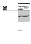
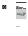
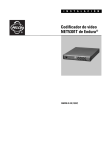
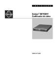
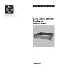
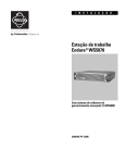
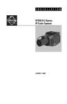
I I NN SS TT AA LL L A T I OO NN
Endura® Workstation
C1619M-I (11/07)
List of Illustrations
1
2
3
4
5
6
7
8
9
10
11
12
13
14
15
4
Major Package Components. . . . . . . . . . . . . . . . . . . . . . . . . . . . . . . . . . . . . . . . . . . . . . . . . . . . . . . . . . . . . . . . . . . . . . . . . . . . . . . . . . . . . . . . . 8
Accessories Box . . . . . . . . . . . . . . . . . . . . . . . . . . . . . . . . . . . . . . . . . . . . . . . . . . . . . . . . . . . . . . . . . . . . . . . . . . . . . . . . . . . . . . . . . . . . . . . . . . 8
Rack Mount Kit . . . . . . . . . . . . . . . . . . . . . . . . . . . . . . . . . . . . . . . . . . . . . . . . . . . . . . . . . . . . . . . . . . . . . . . . . . . . . . . . . . . . . . . . . . . . . . . . . . . 9
Extra Product Serial Number Label. . . . . . . . . . . . . . . . . . . . . . . . . . . . . . . . . . . . . . . . . . . . . . . . . . . . . . . . . . . . . . . . . . . . . . . . . . . . . . . . . . . . 9
Chassis Brackets and Rubber Feet . . . . . . . . . . . . . . . . . . . . . . . . . . . . . . . . . . . . . . . . . . . . . . . . . . . . . . . . . . . . . . . . . . . . . . . . . . . . . . . . . . . 10
Assembling a Support Rail . . . . . . . . . . . . . . . . . . . . . . . . . . . . . . . . . . . . . . . . . . . . . . . . . . . . . . . . . . . . . . . . . . . . . . . . . . . . . . . . . . . . . . . . . 11
Inserting Cage Nuts . . . . . . . . . . . . . . . . . . . . . . . . . . . . . . . . . . . . . . . . . . . . . . . . . . . . . . . . . . . . . . . . . . . . . . . . . . . . . . . . . . . . . . . . . . . . . . 12
Attaching Support Rails . . . . . . . . . . . . . . . . . . . . . . . . . . . . . . . . . . . . . . . . . . . . . . . . . . . . . . . . . . . . . . . . . . . . . . . . . . . . . . . . . . . . . . . . . . . 13
Mounting the Endura Workstation into the Rack. . . . . . . . . . . . . . . . . . . . . . . . . . . . . . . . . . . . . . . . . . . . . . . . . . . . . . . . . . . . . . . . . . . . . . . . 14
Tightening the Thumbscrews . . . . . . . . . . . . . . . . . . . . . . . . . . . . . . . . . . . . . . . . . . . . . . . . . . . . . . . . . . . . . . . . . . . . . . . . . . . . . . . . . . . . . . . 14
Rear Panel of Endura Workstation . . . . . . . . . . . . . . . . . . . . . . . . . . . . . . . . . . . . . . . . . . . . . . . . . . . . . . . . . . . . . . . . . . . . . . . . . . . . . . . . . . . 15
Front Panel of Endura Workstation (Bezel Open) . . . . . . . . . . . . . . . . . . . . . . . . . . . . . . . . . . . . . . . . . . . . . . . . . . . . . . . . . . . . . . . . . . . . . . . . 16
Endura Workstation Front Panel Indicators . . . . . . . . . . . . . . . . . . . . . . . . . . . . . . . . . . . . . . . . . . . . . . . . . . . . . . . . . . . . . . . . . . . . . . . . . . . . 17
Locating and Starting the Installation Program . . . . . . . . . . . . . . . . . . . . . . . . . . . . . . . . . . . . . . . . . . . . . . . . . . . . . . . . . . . . . . . . . . . . . . . . . 18
Installation Welcome Screen . . . . . . . . . . . . . . . . . . . . . . . . . . . . . . . . . . . . . . . . . . . . . . . . . . . . . . . . . . . . . . . . . . . . . . . . . . . . . . . . . . . . . . . 18
C1619M-I (11/07)
Contents
Regulatory Notices . . . . . . . . . . . . . . . . . . . . . . . . . . . . . . . . . . . . . . . . . . . . . . . . . . . . . . . . . . . . . . . . . . . . . . . . . . . . . . . . . . . . . . . . . . . . . . . . . . . . 5
Description . . . . . . . . . . . . . . . . . . . . . . . . . . . . . . . . . . . . . . . . . . . . . . . . . . . . . . . . . . . . . . . . . . . . . . . . . . . . . . . . . . . . . . . . . . . . . . . . . . . . . . . . . . 6
Before You Begin . . . . . . . . . . . . . . . . . . . . . . . . . . . . . . . . . . . . . . . . . . . . . . . . . . . . . . . . . . . . . . . . . . . . . . . . . . . . . . . . . . . . . . . . . . . . . . . . . . . . . 7
Parts List . . . . . . . . . . . . . . . . . . . . . . . . . . . . . . . . . . . . . . . . . . . . . . . . . . . . . . . . . . . . . . . . . . . . . . . . . . . . . . . . . . . . . . . . . . . . . . . . . . . . . . . 7
Package Contents . . . . . . . . . . . . . . . . . . . . . . . . . . . . . . . . . . . . . . . . . . . . . . . . . . . . . . . . . . . . . . . . . . . . . . . . . . . . . . . . . . . . . . . . . . . . . . . . 8
Product Serial Number Label Placement . . . . . . . . . . . . . . . . . . . . . . . . . . . . . . . . . . . . . . . . . . . . . . . . . . . . . . . . . . . . . . . . . . . . . . . . . . . . . . . 9
Equipment Placement and Rack Mounting . . . . . . . . . . . . . . . . . . . . . . . . . . . . . . . . . . . . . . . . . . . . . . . . . . . . . . . . . . . . . . . . . . . . . . . . . . . . . . . . . 10
Desktop Mounting . . . . . . . . . . . . . . . . . . . . . . . . . . . . . . . . . . . . . . . . . . . . . . . . . . . . . . . . . . . . . . . . . . . . . . . . . . . . . . . . . . . . . . . . . . . . . . . 10
Rack Mounting . . . . . . . . . . . . . . . . . . . . . . . . . . . . . . . . . . . . . . . . . . . . . . . . . . . . . . . . . . . . . . . . . . . . . . . . . . . . . . . . . . . . . . . . . . . . . . . . . . 11
Connections . . . . . . . . . . . . . . . . . . . . . . . . . . . . . . . . . . . . . . . . . . . . . . . . . . . . . . . . . . . . . . . . . . . . . . . . . . . . . . . . . . . . . . . . . . . . . . . . . . . . . . . . 15
Operation . . . . . . . . . . . . . . . . . . . . . . . . . . . . . . . . . . . . . . . . . . . . . . . . . . . . . . . . . . . . . . . . . . . . . . . . . . . . . . . . . . . . . . . . . . . . . . . . . . . . . . . . . . 17
Front Panel Indicators . . . . . . . . . . . . . . . . . . . . . . . . . . . . . . . . . . . . . . . . . . . . . . . . . . . . . . . . . . . . . . . . . . . . . . . . . . . . . . . . . . . . . . . . . . . . 17
Configuration/Reset Button . . . . . . . . . . . . . . . . . . . . . . . . . . . . . . . . . . . . . . . . . . . . . . . . . . . . . . . . . . . . . . . . . . . . . . . . . . . . . . . . . . . . . . . . 17
Updating the WS5000 Advanced System Software . . . . . . . . . . . . . . . . . . . . . . . . . . . . . . . . . . . . . . . . . . . . . . . . . . . . . . . . . . . . . . . . . . . . . . . . . 18
Installing the Application . . . . . . . . . . . . . . . . . . . . . . . . . . . . . . . . . . . . . . . . . . . . . . . . . . . . . . . . . . . . . . . . . . . . . . . . . . . . . . . . . . . . . . . . . . 18
Troubleshooting . . . . . . . . . . . . . . . . . . . . . . . . . . . . . . . . . . . . . . . . . . . . . . . . . . . . . . . . . . . . . . . . . . . . . . . . . . . . . . . . . . . . . . . . . . . . . . . . . . . . . 19
Specifications . . . . . . . . . . . . . . . . . . . . . . . . . . . . . . . . . . . . . . . . . . . . . . . . . . . . . . . . . . . . . . . . . . . . . . . . . . . . . . . . . . . . . . . . . . . . . . . . . . . . . . . 20
C1619M-I (11/07)
3
Regulatory Notices
This device complies with Part 15 of the FCC Rules. Operation is subject to the following two conditions: (1) this device may not cause harmful
interference, and (2) this device must accept any interference received, including interference that may cause undesired operation.
RADIO AND TELEVISION INTERFERENCE
This equipment has been tested and found to comply with the limits of a Class A digital device, pursuant to Part 15 of the FCC rules. These limits
are designed to provide reasonable protection against harmful interference when the equipment is operated in a commercial environment.
This equipment generates, uses, and can radiate radio frequency energy and, if not installed and used in accordance with the instruction manual,
may cause harmful interference to radio communications. Operation of this equipment in a residential area is likely to cause harmful interference
in which case the user will be required to correct the interference at his own expense.
Changes and Modifications not expressly approved by the manufacturer or registrant of this equipment can void your authority to operate this
equipment under Federal Communications Commission’s rules.
In order to maintain compliance with FCC regulations shielded cables must be used with this equipment. Operation with non-approved
equipment or unshielded cables is likely to result in interference to radio and television reception.
This Class A digital apparatus complies with Canadian ICES-003.
Cet appareil numérique de la classe A est conforme à la norme NMB-003 du Canada.
Video Quality Caution
FRAME RATE NOTICE REGARDING USER-SELECTED OPTIONS
Pelco systems are capable of providing high quality video for both live viewing and playback. However, the systems can be used in lower quality
modes, which can degrade picture quality, to allow for a slower rate of data transfer and to reduce the amount of video data stored. The picture
quality can be degraded by either lowering the resolution, reducing the picture rate, or both. A picture degraded by having a reduced resolution
may result in an image that is less clear or even indiscernible. A picture degraded by reducing the picture rate has fewer frames per second,
which can result in images that appear to jump or move more quickly than normal during playback. Lower frame rates may result in a key event
not being recorded by the system.
Judgment as to the suitability of the products for user’s purposes is solely the user’s responsibility. Users shall determine the suitability of the
products for their own intended application, picture rate and picture quality. In the event user intends to use the video for evidentiary purposes
in a judicial proceeding or otherwise, user should consult with its attorney regarding any particular requirements for such use.
C1619M-I (11/07)
5
Description
The Endura® workstation is a high-end personal computer designed to deliver optimum performance for the WS5000 advanced system software.
The Endura workstation has two video outputs, a USB keyboard, and a mouse. The Endura workstation can decode and display up to 16 video
streams simultaneously. Up to 16 streams can be displayed at a full 4CIF resolution at 30/25 (NTSC/PAL) images per second per stream. The
Endura workstation includes a single license of the WS5000 advanced system software.
The WS5000 advanced system software is a graphical user interface software that provides access to all operation and configuration features of
the Endura system in one unified, user-friendly interface. The interface uses drag and drop operations, shortcut menus, and tooltips to enable the
most direct, intuitive interactions. Sound, graphics, color, and on-screen messages provide helpful, ongoing feedback about user activity and
system status.
With this software users can view live video; control cameras; record video; and search, play back, and export recorded video. Video display
options include a single image (1 x 1), four images (2 x 2), nine images (3 x 3), sixteen images (4 x 4), six images (1 large + 5 small), ten images
(2 large + 8 small), and 13 images (1 large + 12 small). When multiple images are displayed, the patent pending EnduraView technology
automatically adjusts the video display frame rates to provide the best rate for the cameras. Cameras can be assigned to a user-defined location or
camera group; these locations and groups can then be used in the display, sorting, and selection of devices—a feature especially valuable in larger
systems.
The WS5000 advanced system software also allows users with the proper authority to perform administrative functions, such as configuring
devices, setting up users, adjusting network settings, and creating recording schedules. Permissions to access these functions and all other
system services can be configured to a fine level of detail. Users see only those devices and features to which they have been granted
permission.
The WS5000 advanced system software offers a powerful scripting interface. With scripts, users can flexibly and easily automate many system
functions in almost any combination. An enhanced search interface enables searches across multiple devices, time ranges, and event types.
System logs can also be searched, printed, and exported. A front panel USB port and DVD±RW/CD-RW drive make it easy to export video clips
and still images to external media.
6
C1619M-I (11/07)
Before You Begin
Endura is a network system that requires a continuous amount of bandwidth to transmit true, live video. Therefore, always include your network
administrator when planning and installing Endura components.
You will also need the following:
•
Pelco-approved Endura certification
•
Access to an Endura network
–
that is an active, gigabit Ethernet network that supports the full Internet Protocol suite,
–
that is configured with at least one Endura video recorder,
–
that is configured with at least one SM5000 system manager
•
One or more monitors (1280 x 1024 VGA or DVI)
•
Phillips screwdriver (if mounting the unit into a rack)
•
Cat5e (or better) network cable
PARTS LIST
Qty Description
1
Pelco Endura workstation with WS5000 advanced system software installed
1
Standard PC USB keyboard
1
Standard USB mouse
1
Rack-mounting kit:
2 Chassis mounting brackets with handles and thumb screws
8 Screws, 10-32 x 0.25-inch, Phillips, pan head (4 for each bracket)
2 Adjustable support rail sets (each set includes 1 front-mounting rail and 1 rear-mounting rail)
6 Screws, 8-32 x 0.375-inch, Phillips, truss head
4 Screws, 10-32 x 0.5-inch, Phillips, flat head (2 for each front-mounting rail)
4 Screws, 10-32 x 0.75-inch, Phillips, pan head (2 for each rear-mounting rail)
10 Cage nuts (for use with square-hole racks)
2
DVI-to-VGA video adapter
3
Power cables (1 USA standard, 1 European standard, and 1 UK standard)
2
Keys
3
Product identification labels (attached to unit)
1
Endura workstation Installation manual
1
WS5000 Operation manual
1
Endura workstation Quick Start Guide
1
Important Safety Instructions
1
Endura Installation and Programming Checklist
1
Resource CD
1
Recovery DVD
1
Nero® installation CD
1
Microsoft® Windows®XP Professional CD
C1619M-I (11/07)
7
PACKAGE CONTENTS
The following diagrams show the contents of the two boxes. When installing the Endura workstation, refer to these diagrams.
SHIPPING BOX
SAFETY INSTRUCTIONS
INSTALLATION MANUAL
QUICK START GUIDE
INSTALLATION AND
PROGRAMMING CHECKLIST
OPERATION MANUAL
ACCESSORY PACK
WS5000 SERIES
ENDURA WORKSTATION
Figure 1. Major Package Components
ACCESSORY PACK
STANDARD USB
KEYBOARD AND MOUSE
RACK MOUNT KIT
RECOVERY DVD
FRONT BEZEL KEY
2 EA.
RESOURCE CD WITH
ALL MANUALS
NERO INSTALLATION CD
DVI TO VGA
VIDEO ADAPTER
MICROSOFT WINDOWS XP
PROFESSIONAL CD
USA
STANDARD POWER
CORD (110 VAC)
1 EA.
EUROPEAN
STANDARD POWER
CORD (220 VAC)
1 EA.
UK
STANDARD POWER
CORD (250 VAC)
1 EA.
Figure 2. Accessories Box
8
C1619M-I (11/07)
REAR MOUNT RAIL
2 EA.
FRONT MOUNT RAIL
2 EA.
RACK MOUNT KIT
CHASSIS MOUNTING
BRACKETS
SHOWN ACTUAL SIZE
PHILLIPS PAN
HEAD SCREW,
10-32 X 0.25-INCH
8 EA.
PHILLIPS TRUSS
HEAD SCREW,
8-32 X 0.375-INCH
6 EA.
PHILLIPS FLAT
HEAD SCREW,
10-32 X 0.5-INCH
4 EA.
PHILLIPS PAN
HEAD SCREW,
10-32 X 0.75-INCH
4 EA.
CAGE NUT,
10-32
10 EA.
Figure 3. Rack Mount Kit
PRODUCT SERIAL NUMBER LABEL PLACEMENT
Product serial number labels help Pelco’s Product Support identify your system and its factory configuration in the event that your Endura
workstation or its components require service.
Three labels citing your product’s serial number are attached to the Endura workstation. One label is attached to the bottom of the Endura
workstation. A second label is attached to the front panel of the unit, behind the bezel.
Because rack mounting and other installation options may obscure the factory-applied labels, a third label is provided for you to attach to your
product documentation or another product location that will not be obscured by installation. To use this label:
1. Locate the small label attached to the outside of the front bezel with a yellow sticker that reads “Extra serial number label: remove prior to
installation.”
2. Remove the yellow sticker.
3. Peel away the backing of the small white label and attach it to this Installation manual, other product documentation, or an unobscured
product location.
03267-39-0020
SN
Figure 4. Extra Product Serial Number Label
C1619M-I (11/07)
9
Equipment Placement and Rack Mounting
The Endura workstation can be placed on a flat surface, such as a desktop, or mounted in an equipment rack.
DESKTOP MOUNTING
WARNING: Do not place the Endura workstation unit on its side; in this position, the unit is likely to fall over and may cause equipment
damage or personal injury.
To mount the Endura workstation on a desktop:
1. To prevent surface damage, be sure that the rubber feet are securely installed on the four corners of the bottom of the unit.
2. Remove the two chassis brackets (if attached) from the sides of the unit, using a Phillips screwdriver to remove the eight 10-32 x 0.25-inch
Phillips pan head screws (four per bracket). Save the brackets and screws for possible future use.
3. Position the unit to allow for cable and power cord clearance at the rear of the unit. Be sure that the air flow around the unit is not obstructed.
(4) SCREWS
PER BRACKET,
10.32 X 0.25-INCH
PHILLIPS PAN HEAD
CHASSIS
BRACKET
RUBBER FEET
(4) SCREWS,
8-32 X 0.25-INCH
PHILLIPS PAN HEAD
Figure 5. Chassis Brackets and Rubber Feet
10
C1619M-I (11/07)
RACK MOUNTING
The Endura workstation mounts into an industry-standard 19-inch (48 cm) equipment rack. The Endura workstation occupies two rack units
(3.5 inches or 8.9 cm) of vertical rack space. The hardware necessary to mount the Endura workstation into a rack is supplied with the unit.
The rack must meet the following requirements:
•
Rack standard: 19-inch EIA-310-D compliant (rear column required).
•
Rack column depth: 20 to 30 inches (50.8 to 76.2 cm).
•
Column mounting hole provisions: 10-32 UNF-2B threaded holes or square window holes on front and rear columns.
•
Door systems (optional): Front doors must have at least 2 inches (5.1 cm) between the Endura workstation front bezel and the inside of the
door. Rear doors may be used only on rack columns that are more than 26 inches (66.0 cm) deep.
WARNING: Slots and openings in the cabinet provide ventilation to prevent the unit from overheating. Do not block these openings.
Never place the unit near or over a radiator or heat register. When placing the unit in a built-in installation, such as a rack, be sure to
provide proper ventilation. Allow at least one rack unit (1.75 inches or 4.44 cm) of spacing between units.
NOTE: Figure 3 identifies each piece of hardware for this procedure.
To install the Endura workstation in a rack:
1. If chassis mounting brackets are not attached: Attach one mounting bracket to each side of the Endura workstation. Use four 10-32 x 0.25-inch
Phillips pan head screws for each bracket. Attach the brackets so that the tapered ends are positioned toward the rear of the Endura
workstation. Refer to Figure 5.
2. Remove the four rubber feet from the underside of the unit if they are attached. Save the rubber feet and screws for possible future use.
3. Attach one front-mount rail to one rear-mount rail. Make sure the rails are mounted back to back, as shown in Figure 6. Use three
8-32 x 0.375-inch Phillips truss head screws in any of the available holes. Leave the screws loose until step 8.
(3) SCREWS, 8-32 X 0.375
PHILLIPS TRUSS HEAD
Figure 6. Assembling a Support Rail
4. Repeat step 3 for the other rail set.
C1619M-I (11/07)
11
5. If installing unit into a square-hole rack: Insert 10 cage nuts into the square-hole rack as shown in Figure 7.
CAGE NUT
Figure 7. Inserting Cage Nuts
6. Attach one support rail assembly to the equipment rack in the desired location (refer to Figure 8).
NOTE: The support rail assemblies are identical and may be used on either the right or left side of the rack.
12
a.
Position the ear of the front-mount rail against the front of the equipment rack. Align the top and bottom holes in the ear of the rail
with the threaded holes (or cage nuts) in the rack.
b.
Using two 10-32 x 0.5-inch Phillips flat head screws, attach the ear of the rail to the front of the rack. Insert the screws from the
outside of the rack, pointing rearward.
c.
Adjust the rails to the correct depth of the equipment rack by sliding the rear-mount rail to the back of the equipment rack.
d.
Position the ear of the rear-mount rail against the rear exterior of the equipment rack. Align the top and bottom holes in the ear of the
rail section with the threaded holes (or cage nuts) in the equipment rack.
e.
Using two 10-32 x 0.75-inch Phillips pan head screws, attach the ear of the rail to the rear of the rack. Insert the screws from the
outside of the rack, pointing forward.
C1619M-I (11/07)
RACK FRONT
RACK REAR
(4) SCREWS,
10-32 X 0.5-INCH
PHILLIPS FLAT HEAD
(4) SCREWS,
10-32 X 0.75-INCH
PHILLIPS PAN HEAD
FRONT-MOUNT RAIL
REAR-MOUNT RAIL
Figure 8. Attaching Support Rails
7. Repeat step 6 for the second support rail assembly.
8. Tighten the 8-32 x 0.375-inch Phillips truss head screws that were attached to the front- and rear-mount rails in steps 3 and 4.
C1619M-I (11/07)
13
9. Place the unit onto the mount rails by sliding the chassis brackets onto the rails. This step may require two people to lift and slide the unit
into place. The unit should slide in and out of the rack easily. Refer to Figure 9.
WARNING: When sliding out the Endura workstation, be careful not to let the unit fall out of the rack.
Figure 9. Mounting the Endura Workstation into the Rack
10. After the unit is in place, tighten the two thumbscrews to secure the unit to the rack.
THUMBSCREW
THUMBSCREW
Figure 10. Tightening the Thumbscrews
14
C1619M-I (11/07)
Connections
1. Connect video output.
The Endura workstation can support two video outputs to a digital video interface (DVI) output. Connect a DVI cable from the DVI output to
the digital monitor’s input connector. To connect a VGA monitor to this output, use a DVI-to-VGA adapter plug supplied with the Endura
workstation.
2. Connect audio input and output. The Endura workstation supports bidirectional audio. This lets you control a loudspeaker or other audio
equipment, such as a door intercom system, at the monitored location. There are two connectors for receiving audio (one for a preamplified
audio line input and one for a microphone) and one connector for audio output.
•
•
•
Audio in: Connect a preamplified audio device to the audio input stereo jack.
Audio out: Connect a speaker or other audio output device to the audio output stereo jack. The line output has an adjustable level of
up to 3 Vp-p with a minimum load of 8 ohms.
Microphone in: Connect a microphone to the microphone stereo jack.
3. Connect a 1000 Base-T Cat5e (or better) cable to the network connector on the rear panel and to the network switch.
4. Use the USB 2.0 ports (front or rear of the unit) to connect the USB keyboard and mouse supplied with the unit. Alternatively, you may
connect a KBD5000 keyboard (sold separately). USB cables connecting the KBD5000 to the Endura workstation may be no more than 9.8 ft
(3 m) long.
5. Connect power. Plug the power cord (either the USA standard, UK standard, or European standard cable that is provided) into the rear of the
unit, and then plug the cord into the wall. The Endura workstation uses a 100-240 VAC power supply.
USB 2.0 PORTS
POWER CONNECTOR
NETWORK
CONNECTOR (RJ-45)
DIGITAL VIDEO (DVI)
CONNECTORS
MICROPHONE IN
AUDIO OUT
AUDIO IN
Figure 11. Rear Panel of Endura Workstation
6. Turn on the unit:
a.
Using one of the keys that came with the unit, open the bezel by swinging it on its hinge away from the front of the unit.
b.
Turn on the Endura workstation by momentarily pressing the black power button on the front of the unit.
WARNING: Pressing and holding the power button for four seconds shuts down the unit. Do not shut down the unit in this manner unless
the unit does not shut down properly through the Windows® operating system.
C1619M-I (11/07)
c.
Close the front bezel.
d.
Check indicators:
•
The Pelco badge on the front panel should glow blue if the bezel is closed and the power is on. If the bezel is open, the power
indicator should glow white.
•
The unit status indicator should glow solid green after the unit starts up.
•
The network status indicator on the front panel shows the network connection speed and status. To interpret the network
indicator colors, refer to “Front Panel Indicators” on page 17.
15
POWER BUTTON
DVD/CD
DRIVE
POWER INDICATOR
CPU ACTIVITY
NETWORK
ACTIVITY
NETWORK STATUS
03267-39-0020
SN
UNIT STATUS
PRODUCT SERIAL NUMBER STICKER
CONFIGURATION/
RESET BUTTON
USB 2.0 PORT
Figure 12. Front Panel of Endura Workstation (Bezel Open)
16
C1619M-I (11/07)
Operation
Refer to the WS5000 Operation manual for details on how to configure and operate the system. Do not install other software on this unit as
video performance may suffer.
FRONT PANEL INDICATORS
Figure 13. Endura Workstation Front Panel Indicators
Front Panel Lock and Key
The front panel lock and key secure the unit from tampering.
CPU activity indicator
The CPU status indicator flashes yellow when there is CPU activity.
Network activity indicator
The activity indicator flashes green when the unit is sending or receiving network data.
Network status indicator
The network status LED indicates the network connection and speed. It may display one of the following conditions:
Off
The unit is not connected to the network.
Solid Green The unit is connected to the network using the 1000Base-T standard.
Solid Yellow The unit is connected to the network using the 100Base-T standard.
Solid Red
The unit is connected to the network using the 10Base-T standard.
Unit status indicator
The unit status is indicated by one of the following three colors:
Green
The unit is functioning normally.
Yellow
The unit is in configuration mode.
Red
The unit is in an error condition.
Pelco badge (power indicator)
The Pelco badge, on the left side of the unit, glows blue when the unit has power. Behind the front bezel, the power
indicator LED is white.
CONFIGURATION/RESET BUTTON
The white configuration/reset button on the front panel is reserved for future use (refer to Figure 12).
C1619M-I (11/07)
17
Updating the WS5000 Advanced System Software
The WS5000 advanced system software is updated frequently as Pelco continues to refine and enhance the system, and the latest software
might not be available at the time Endura workstation is shipped. It is therefore recommended that you visit the Certified Partner Portal at the
Pelco Web site (www.pelco.com) periodically to confirm that the unit contains the latest version of the software. After you download any
update, follow the instructions below to install it on the unit.
INSTALLING THE APPLICATION
WARNING: Do not use the Add/Remove Programs feature of Microsoft Windows to remove an existing version of the WS5000. The
updated application depends on components and settings that are present in the existing version. The installation program will remove
the existing software as the newer version is installed.
1. Close the WS5000 if it is running.
2. In Windows Explorer, locate the folder where you downloaded the updated version of the WS5000 and double-click the setup program.
The default name for this program is WS5000 Setup.exe. The program prepares the installation files and displays the Welcome screen
(Figure 15).
Figure 14. Locating and Starting the Installation Program
Figure 15. Installation Welcome Screen
3. Follow the instructions on the installation screens to install the application.
18
C1619M-I (11/07)
Troubleshooting
Consult the WS5000 Operation manual (C1624M) for detailed information on setting up devices that are attached to the Endura system. The
following table provides suggestions to common issues related to the Endura workstation. If those instructions fail to solve your problem, contact
Pelco Product Support at 1-800-289-9100 (USA and Canada) or 1-559-292-1981 (international) for assistance. You should have the serial number
from the label on the front panel of the unit as well as the software version from the unit’s Advanced Properties dialog box.
NOTE: Do not try to repair the unit yourself. Opening it immediately voids any warranty. Leave maintenance and repairs to qualified technical
personnel. Exchange the defective unit and return it for repair.
Table A. Troubleshooting the Endura Workstation
Problem
Possible Causes
Suggested Remedy
Front panel indicators not lit.
Power turned off.
Check the power supply.
Network connection problem.
Faulty network connections.
Visually inspect all network cables and connectors at the unit and
the network switch.
Check the indicators on the network switch.
Other network connectivity issues.
C1619M-I (11/07)
Contact your network administrator or Endura-certified technician.
19
Specifications
SYSTEM
Processor
Intel® Xeon® X3220
Internal Memory
2 GB RAM
Operating System
Microsoft Windows XP Professional Service Pack 2
User Interface
Graphical user interface, WS5000 advanced system software
Video System
PCI-E x16 graphics card with 256 MB video RAM (nonshared memory), 1280 x 1024 display resolution, and
DirectX® 8.1 application programming interface; true color (32 bit), 2 DVI video outputs
VIDEO
Video Standards
XVGA (1280 x 1024)
60 Hz capability for NTSC
75 Hz capability for PAL
Video Coding
MPEG-4
Video Resolutions
4CIF
2CIF
CIF
QCIF
NTSC
704 x 480
704 x 240
352 x 240
176 x 120
Video Display Speed
480/400 ips (NTSC/PAL) in each workspace
Video Display Modes
1 image, 4 images (2 x 2), 9 images (3 x 3), 16 images (4 x 4), 6 images (1 large + 5 small),
10 images (2 large + 8 small), 13 images (1 large + 12 small)
Video Outputs
2 DVI or VGA outputs (2 DVI-to-VGA adapters supplied)
PAL
704 x 576
704 x 288
352 x 288
176 x 144
AUDIO
Audio Decoding
G.711 speech codec
Audio Bit Rate
64 kbps
Audio Levels
Input: electret microphone
Output: up to 3 Vp-p, adjustable, minimum load of 8 ohms
Audio Connectors
3, 3.5 mm stereo jacks
Connector Tip
Signal left (input and output)
Connector Ring
Signal right (input and output)
Connector Sleeve
Common
Audio Inputs
Microphone and line in
Audio Outputs
Speaker or line out
PTZ CONTROL
PTZ Interface
On-screen
NETWORK
Interface
Gigabit Ethernet RJ-45 port (1000 Base-T)
Security
2 modes: secure mode (device authentication) and unsecure mode
AUXILIARY INTERFACES
USB Ports
20
7 USB 2.0 ports (1 front, 6 rear)
C1619M-I (11/07)
FRONT PANEL
DVD±RW/CD-RW Drive
CD read/write speed: 24X
CD rewrite speed: 24X
DVD read/write speed: 8X
DVD dual layer read/write speed: 6X/4X
Buttons
Power, configuration/reset
Indicators
Power: Blue if power
Hard Disk Drive Activity: Yellow when activity
Network Activity: Green when activity
Network Status: Green, yellow, red
Unit Status: Green, yellow, red
POWER
Power Input
100-240 VAC, 50/60 Hz, autoranging
Power Supply
Internal
Power Consumption
100 VAC
115 VAC
220 VAC
Operating Maximum
157 W, 536 BTU/H
163 W, 557 BTU/H
159 W, 543 BTU/H
Cable Type
1, USA standard (117 VAC, 3 prongs, molded connector, 6 ft or 1.8 m)
1, European standard (220 VAC, 3 prongs, molded connector, 6 ft or 1.8 m)
1, UK standard (250 VAC, 3 prongs, molded connector, 6 ft or 1.8 m)
ENVIRONMENTAL
Operating Temperature
70° to 74°F (21° to 23°C) at unit air intake (front of unit)
Storage Temperature
-40° to 149°F (-40° to 65°C)
Operating Humidity
20% to 80%, noncondensing
Maximum Humidity Gradient
10% per hour
Operating Altitude
-50 ft to 10,000 ft (-15 m to 3,048 m)
Operating Vibration
0.25 G at 3 Hz to 200 HZ at a sweep rate of 0.5 octave/min.
PHYSICAL
Construction
Steel cabinet
Finish
Front panel: gray metallic with black end caps; chassis: black matte finish
Dimensions
17.0" (D) x 17.1" (W) x 3.5" (H) (43.2 x 43.4 x 8.9 cm)
Mounting
Desktop (feet) or rack (2 RU per unit)
Unit Weight
28.8 lb (13.06 kg)
STANDARDS/ORGANIZATIONS
•
•
•
•
•
•
C1619M-I (11/07)
Pelco is a member of the MPEG-4 Industry Forum
Pelco is a member of the Universal Plug and Play (UPnP) Forum, Steering Committee
Pelco is a member of the Universal Serial Bus (USB) Implementers Forum
Pelco is a contributor to the International Standards for Organization / Electrotechnical Commission (ISO/IEC) Joint Technical Committee 1
(JTC1), “Information Technology,” Subcommittee 29, Working Group 11
Compliance, ISO/IEC 14496 standard (also known as MPEG-4)
Compliance, International Telecommunication Union (ITU) Recommendation G.711, “Pulse Code Modulation (PCM) of Voice Frequencies”
21
22
C1619M-I (11/07)
PRODUCT WARRANTY AND RETURN INFORMATION
WARRANTY
Pelco will repair or replace, without charge, any merchandise proved defective in material or
workmanship for a period of one year after the date of shipment.
Exceptions to this warranty are as noted below:
• Five years on fiber optic products and TW3000 Series unshielded twisted pair transmission
products.
• Three years on Spectra® IV products.
• Three years on Genex® Series products (multiplexers, server, and keyboard).
• Three years on Camclosure® and fixed camera models, except the CC3701H-2,
CC3701H-2X, CC3751H-2, CC3651H-2X, MC3651H-2, and MC3651H-2X camera models,
which have a five-year warranty.
• Three years on PMCL200/300/400 Series LCD monitors.
• Two years on standard motorized or fixed focal length lenses.
• Two years on Legacy®, CM6700/CM6800/CM9700 Series matrix, and DF5/DF8 Series fixed
dome products.
• Two years on Spectra III™, Esprit®, ExSite®, and PS20 scanners, including when used in
continuous motion applications.
• Two years on Esprit and WW5700 Series window wiper (excluding wiper blades).
• Two years (except lamp and color wheel) on Digital Light Processing (DLP®) displays.
The lamp and color wheel will be covered for a period of 90 days. The air filter is not
covered under warranty.
• Eighteen months on DX Series digital video recorders, NVR300 Series network video
recorders, and Endura® Series distributed network-based video products.
• One year (except video heads) on video cassette recorders (VCRs). Video heads will be
covered for a period of six months.
• Six months on all pan and tilts, scanners or preset lenses used in continuous motion
applications (that is, preset scan, tour and auto scan modes).
Pelco will warrant all replacement parts and repairs for 90 days from the date of Pelco
shipment. All goods requiring warranty repair shall be sent freight prepaid to Pelco, Clovis,
California. Repairs made necessary by reason of misuse, alteration, normal wear, or accident
are not covered under this warranty.
Pelco assumes no risk and shall be subject to no liability for damages or loss resulting from
the specific use or application made of the Products. Pelco’s liability for any claim, whether
based on breach of contract, negligence, infringement of any rights of any party or product
liability, relating to the Products shall not exceed the price paid by the Dealer to Pelco for such
Products. In no event will Pelco be liable for any special, incidental or consequential damages
(including loss of use, loss of profit and claims of third parties) however caused, whether by
the negligence of Pelco or otherwise.
The above warranty provides the Dealer with specific legal rights. The Dealer may also have
additional rights, which are subject to variation from state to state.
If a warranty repair is required, the Dealer must contact Pelco at (800) 289-9100 or
(559) 292-1981 to obtain a Repair Authorization number (RA), and provide the following
information:
1. Model and serial number
2. Date of shipment, P.O. number, Sales Order number, or Pelco invoice number
3. Details of the defect or problem
If there is a dispute regarding the warranty of a product which does not fall under the
warranty conditions stated above, please include a written explanation with the product when
returned.
Method of return shipment shall be the same or equal to the method by which the item was
received by Pelco.
RETURNS
In order to expedite parts returned to the factory for repair or credit, please call the factory at
(800) 289-9100 or (559) 292-1981 to obtain an authorization number (CA number if returned for
credit, and RA number if returned for repair).
All merchandise returned for credit may be subject to a 20% restocking and refurbishing
charge.
Goods returned for repair or credit should be clearly identified with the assigned CA or RA
number and freight should be prepaid. Ship to the appropriate address below.
If you are located within the continental U.S., Alaska, Hawaii or Puerto Rico, send goods to:
Service Department
Pelco
3500 Pelco Way
Clovis, CA 93612-5699
If you are located outside the continental U.S., Alaska, Hawaii or Puerto Rico and are instructed
to return goods to the USA, you may do one of the following:
If the goods are to be sent by a COURIER SERVICE, send the goods to:
Pelco
3500 Pelco Way
Clovis, CA 93612-5699 USA
If the goods are to be sent by a FREIGHT FORWARDER, send the goods to:
Pelco c/o Expeditors
473 Eccles Avenue
South San Francisco, CA 94080 USA
Phone: 650-737-1700
Fax: 650-737-0933
The materials used in the manufacture of this document and its components are compliant to the requirements of Directive 2002/95/EC.
This equipment contains electrical or electronic components that must be recycled properly to comply with Directive 2002/96/EC of the European Union
regarding the disposal of waste electrical and electronic equipment (WEEE). Contact your local dealer for procedures for recycling this equipment.
REVISION HISTORY
Manual #
C1619M
C1619M-A
C1619M-B
C1619M-C
C1619M-D
C1619M-E
C1619M-F
C1619M-G
C1619M-H
C1619M-I
Date
1/05
5/05
7/05
8/05
3/06
5/06
10/06
2/07
10/07
11/07
Comments
Original version.
Revised to reflect a specification change.
Revised to reflect specification changes and package contents.
Revised rack mounting instructions, package contents, and serial number placement.
Revised back panel illustration to reflect a specification change made in ECO 06-14212.
Revised back panel illustration to reflect a specification change made in ECO 06-14497.
Revised the operating temperature ranges. Added ambient temperature range.
Added software update instructions.
Updated trademarks, software update instructions, product illustrations, and specifications to reflect the WS5060 models.
Updated Operating Temperature values.
Pelco, the Pelco logo, Spectra, Genex, Legacy, Endura, Esprit, ExSite, and Camclosure are registered trademarks of Pelco.
Spectra III is a trademark of Pelco.
Microsoft, Windows, and DirectX are registered trademarks of Microsoft Corporation in the United States and/or other countries.
Intel and Xeon are registered trademarks of Intel Corporation.
Nero is a registered trademark of NeroAG and its subsidiaries.
DLP is a registered trademark of Texas Instruments Incorporated.
©Copyright 2007, Pelco. All rights reserved.
Worldwide Headquarters
3500 Pelco Way
Clovis, California 93612 USA
USA & Canada
Tel: 800/289-9100
Fax: 800/289-9150
International
Tel: 1-559/292-1981
Fax: 1-559/348-1120
www.pelco.com
ISO9001
Australia
| Canada | Finland | France | Germany | Italy | Macau | The Netherlands | Russia | Singapore
| Spain | Sweden | United Arab Emirates | United Kingdom | United States
South Africa