1
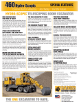
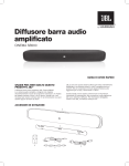
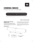
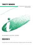
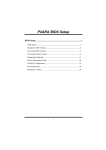
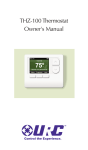
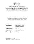
TC170 THERMOSTAT
INSTALLATION
▲WARNING
!
• READ THESE INSTRUCTIONS CAREFULLY BEFORE
ATTEMPTING TO INSTALL, OPERATE OR SERVICE THIS
THERMOSTAT.
• Failure to observe safety information and comply with instructions could result in PERSONAL INJURY, DEATH AND/OR
PROPERTY DAMAGE.
• To avoid electrical shock or damage to equipment, disconnect
power before installing or servicing and use only wiring with
insulation rated for full thermostat operating voltage.
• Before installing this control, the Voltage Selection Switch must
be placed in the correct position. See instructions.
• To avoid potential fire and/or explosion do not use in potentially
flammable or explosive atmospheres.
• Retain these instructions for future reference. This product,
when installed, will be part of an engineered system whose
specifications and performance characteristics are not designed
or controlled by PECO. You must review your application and
national and local codes to assure that your installation will be
functional and safe.
CAUTION
• Use copper wire only, insulate or wire nut all unused leads.
• Care should be used to avoid electrostatic discharge to the T170
thermostat.
• This unit has configuration jumpers. You may need to reconfigure
this thermostat for your application. See page 3.
MOUNTING THE THERMOSTAT
Thermostat mounts to a 4x4 box with a 2x4 mud ring.
CAUTION
All wiring connections must be made
inside the electric box or the T170
maybe damaged.
2x4 Mud Ring
Cover Locking Snaps
(Both Sides)
T170 Base
1. This thermostat is a 24 VAC only control. Leave the Voltage Selection Switch in the 24 VAC position for proper operation. Failure to
select the correct voltage will result in thermostat malfunction or permanent thermostat damage.
2. Connect wires using the wiring diagram. Wire nut off all unused wires.
All connections must be located in the outlet box.
3. Install the T170 base with the two furnished mounting screws to
a standard 4 x 4 x 2-1/8” square device box with a 2” x 4” mud ring
mounted horizontally. Tighten the screws evenly but do not over tighten.
4. To use a remote sensor on units with local sensing capability, remove
jumper JP-1 to disable local sensing. Failure to remove JP-1 will cause
improper operation of the thermostat with a remote probe installed.
5. Verify that the circuit board is firmly snapped into the cover and has
not been dislodged during handling.
6. Install the cover assembly. Press firmly to engage the cover locking
snaps.
7. Checkout: After wiring and installation is complete, energize the
system. Set fan to ON. Set the system button to AUTO, or available
selection. Using the UP arrow, adjust temperature above the ambient
temperature to cycle heating stage(s) on. Using the DOWN arrow adjust
the temperature below ambient temperature to cycle cooling stage(s)
on.
TYPICAL OPERATION
System Button Operation
OFF
All thermostat outputs are off.
AUTO The thermostat automatically selects heating or cooling mode
depending upon the set point and room temperature. The appropriate HEAT or COOL icon are illuminated if demand exists.
A 3°F dead-band is provided to prevent short cycling between
heating and cooling modes. After changeover, the control point
automatically shifts so that the control off point equals the set
point temperature.
COOL The thermostat operates as a cooling only thermostat.
HEAT The thermostat operates as a heating only thermostat.
Up/Down Arrow Button Operation
Up/Down arrows increased or decreased temperature.
Fan Button Operation
In ON the fan output is continuous. In AUTO the output cycles with
demand. Some models are available with Controlled Off and or Staged
Fan.
F/C Button Operation
This button toggles from Fahrenheit to Celsius.
Speed Button Operation
Some models have a Speed button instead of a F/C button. Fan speed
is determined by manual selection of HI or LO. Holding this button in
for 5 seconds will toggle the displayed temperature from Fahrenheit to
Celsius.
T170 Cover Assembly
© COPYRIGHT 2008 PECO, INC. ALL RIGHTS RESERVED.
P/N 69289 3220-2083 REV 0 PAGE 1
• Occupancy Detection
• Setback Operation
• Door Switch Only Operation
Occupancy Detection
Install jumper JP3.
The T170 can be used with the PECO S200 series occupancy detection
equipment. The occupancy and door switch inputs are designed to connect to the SB200 slave sensor and SE200 door switch. The Occupancy
sensor switch is open when there is occupancy and closed when
unoccupied. The Door Switch is open when the door is open and closed
when the door is closed. This system requires both an Occupancy Sensor and a Door Switch. Operation is as follows:
FROM OCCUPIED MODE:
1. A door close signal initiates an occupancy status detection.
2. If occupancy is detected the T170 will maintain normal HVAC
control. It then waits for a door open signal before determining
occupancy again.
3. If no occupancy signal is detected within 2 minutes the T170
changes to unoccupied mode and controls at setback values.
FROM UNOCCUPIED MODE:
1. The T170 continually monitors the room.
2. Any occupancy detection, including door open, will set the operation to occupied mode.
In either mode, if the door is left open for more that 2 minutes the T170
will disable the HVAC system. A one-time ten minute override can be
initiated by pressing any thermostat key pad.
In an Occupied State the thermostat operates normally and looks for a
door close. In the Unoccupied State the thermostat sets heating and
cooling set points to setback values, as determined by factory or user
settings. In this mode the fan is automatically set to cycle with demand.
The T170 will continue to monitor the occupancy sensor and will go to
occupied state anytime occupancy is detected.
Setback Operation
Remove jumper JP3.
This is a low level switch input that is normally open. When closed
the T170 Heating and Cooling setback limits are used as temperature
control points. Fan operation in setback is cycled with demand. Pressing
any button will override setback for 1 hour. Setback will override any
user setting except if the control is turned to OFF. Units with a controlled
off factory setting will override the OFF setting.
Intelligent occupancy sensors like the SD200-001 and SD200-002 can
be used with this input to set the HVAC system to control at setback
limits.
Door Switch Only Operation
Install jumper JP3.
A stand alone door switch can be connected to the T170 to disable the
HVAC system if the door is left open for more that 2 minutes. A one-time
ten minute override can be initiated by pressing any thermostat key pad.
CONDENSATE OVERFLOW INTERRUPT
The remote probe input can be used with a condensate overflow switch
(CO), either in conjunction with a remote probe (normally closed CO
switch) or with local sensing (normally open CO switch). When condensate switch activates, the T170 will display the service wrench and
disable all outputs.
Local Sensor Installation
Remote Probe
White/Yellow
Normally
Open
Condensate
Switch
Circuit Common
White/Violet
Remote Probe Installation
Remote Probe
White/Yellow
Normally
Closed
Condensate
Switch
Circuit Common
White/Violet
FAN OPERATION
Your thermostat can be configured for up to two fan speeds. Fan staging
follows the Heat and Cool Staging Separation. Heat and Cool staging
can be user selected to different values.
The FAN button is used to select FAN AUTO or ON. In the Auto position
the fan cycles on with demand for heating or cooling. If ON is selected
the fan will run continuously.
FAN AUTO:
Fan cycles on with demand
FAN 2 ON
(FAN 1 OFF)
FAN ON:
Fan runs continuously
FAN 1 ON
SETPOINT
HVAC SETBACK SYSTEMS
IF
2F
3F
4F
Temperature Demand
CONTROLLED OFF
FACTORY CONFIGURATION
A factory configuration may be provided to ensure minimum heat and
cool requirements. With this configuration the heat and cool outputs are
automatically cycled on at the heat and cool setback limits. Your thermostat may not have this feature.
© COPYRIGHT 2008 PECO, INC. ALL RIGHTS RESERVED.
P/N 69289 3220-2083 REV 0 PAGE 2
WIRING DIAGRAM
OUTPUT
RA TINGS
INPUT
VOLTAGE
VOLTAGE
PILOT
DUTY
24 VAC
24 VAC
24 VA
OUTPUT CONFIGURATION
A table is provided on the inside of the base to document the function of various outputs. The function of
configurable outputs should be filled in when the unit is
installed.
JP4 JUMPER SELECTION
CAUTION:
HIGH -VOL TAGE - REMOVE
POWER BEFORE
JP 4
JP 3
SWITCH
24 V
110277V
JP4 JUMPER
This jumper is temporarily installed at initial power
up to reconfigure outputs 3 through 6. See Output
Configuration.
JP3 JUMPER
JP3 JUMPER SELECTION
SER VICING
JP 1
JP1 JUMPER
This jumper is shipped normally open. Placement
of a jumper onto both pins allows for Occupancy
Detection/ Door switch and Door Switch Only
Operation.
JP1 JUMPER SELECTION
SWITCH POSITION
This switc h i s p laced in the 24V positio n a t t he
factor y. Thi s t hermostat will not functio n
properly if located in 110-277V positio n
CIRCUIT
Removing this jumper allows the sensor to be located in a remote location. Accessory remote probe
sensors are available in standard 60” lengths but
can be extended to meet application requirements.
BOARD
In Cover
© COPYRIGHT 2008 PECO, INC. ALL RIGHTS RESERVED.
P/N 69289 3220-2083 REV 0 PAGE 3
SERVICE MENU
Access to the Service Menu:
1. Hold the UP Arrow and DOWN Arrow buttons down for 5 seconds.
2. Current display icon will be turned off.
3. Service Menu numbers 1 through A are available. The SYSTEM button is used to scroll to the item to be changed.
4. The UP and DOWN buttons adjust the selection.
HOLD BOTH
FOR
5 SECONDS
STEP
THROUGH
MENU NUMBERS
AND
ADJUSTS
MENU
FUNCTIONS
AND
SYSTEM
SERVICE MENU FUNCTIONS
1 - Continuous Set Point Display
At this feature either the F or C icon and the SETPOINT icon will be
displayed. If the Continuous set point display is enabled the SETPOINT
icon will flash. The Up or Down Arrow button will toggle between continuous display of set point and display of zone temperature.
2 - Fan Off Delay
The FAN, OFF and digits are displayed. Digits represent the number of
seconds the fan will stay on after the heating and cooling outputs are
turned off. The Up or Down Arrow button can be depressed to increase /
decrease value from 0-255 seconds.
3 - Range Limit LO
The display reads the current minimum range setting, SETPOINT
icon and LO icon. The Up or Down Arrow button can be depressed to
increase / decrease value..
4 - Range Limit High
The display reads the current maximum temperature range adjustment,
SETPOINT icon and HI icon. The Up or Down Arrow button can be
depressed to increase / decrease value.
5 - Setback Heat
The display reads current temperature range adjustment, the SETBACK
icon and the HEAT icon. The Up or Down Arrow button can be depressed to increase / decrease value.
6 - Setback Cool
The display reads current Cool setback value, the SETBACK icon and
the COOL icon. The Up or Down Arrow button can be depressed to
increase / decrease value.
7 - Zone Temperature Offset
The display reads ones and tenths (0.0) with leading minus sign. The Up
or Down Arrow button can be depressed to increase / decrease value
+/- 9F. Increments are made in 1F and 0.5C.
8 - Keypad Lockout
The ON and OFF icons are displayed. The enabled icon is flashing. OFF
is the default. ON disables the keypad except for entry into the service
menu. The Up or Down Arrow button can be depressed to select the
mode.
9- Heat Stage Separation
The AUX, HEAT and current separation icons are displayed. The value
can be changed from 0-12F using the Up or Down buttons.
A- Cool Stage Separation
The AUX, COOL and current separation icons are displayed. The value
can be changed from 0-12F using the Up or Down buttons.
Note: These values are stored and recalled in the event of a power
failure.
OUTPUT CONFIGURATION MENU
Four of the six TC170 relay outputs can be field configured for heat staging, cool staging, up to 2 fan speeds and a single outside air damper.
Heat stage 1 and Fan low are permanently configured at the factory. The
user is allowed to assign the remaining outputs. Your specific thermostat
may come with a custom configuration for outputs 3-6. These can be
reconfigured in the field.
Output Configuration
Assigning an output is accomplished as follows:
1. Remove Power from the TC170.
2. Install jumper JP4. To enter the Output Configuration Menu the unit
must be powered up with jumper JP4 installed onto both pins.
3. Apply 24 VAC power to the control. On Power up the unit will
display menu CO1. It will then display the icons associated with the
menu item and the current output assignment. It will indicate a Zero if
the menu item is not assigned.
4. Use the SYSTEM key to select the Menu Item you want to assign.
See Menu Designations below.
Menu Item
CO1
CO2
CO3
CO4
CO5
CO6
Description
HEAT STAGE 2
HEAT STAGE 3
COOL STAGE 1
COOL STAGE 2
FAN HIGH
OUTSIDE AIR
Icons Displayed
HEAT and MED
HEAT and HI
COOL and LO
COOL and HI
FAN and HI
AUX and FAN
5. Use the UP/DOWN arrows to select the output number to be assigned. See Output Designations below.
Output
NO. 1
2
3
4
5
6
Wire Color
Blue
Red
White/Brown
White/Red
White/Orange
Brown
Configuration
Heat Stage 1
Fan Low
_______________ User Configured
_______________ User Configured
_______________ User Configured
_______________ User Configured
6. Push/ Select the F/C key to assign the output to the menu item.
The associated relay will energize when the output is assigned. Note:
If you do not push the F/C key the output will not be assigned. When a
function is assigned to an output, any previous functions that were assigned to that output will be disabled and become unassigned.
7. When configuration is complete turn power off and remove JP4.
Unit is now ready for operation and checkout.
NOTE: With JP4 installed no other control operation is available.
© COPYRIGHT 2008 PECO, INC. ALL RIGHTS RESERVED.
P/N 69289 3220-2083 REV 0 PAGE 4