1
PR™ 10P Powered bi-amplified two-way speaker system · Operations Manual
For more information on other great Peavey products, go to your local Peavey dealer or online at www.peavey.com.
Intended to alert the user to the presence of uninsulated “dangerous voltage” within the product’s
enclosure that may be of sufficient magnitude to constitute a risk of electric shock to persons.
Intended to alert the user of the presence of important operating and maintenance (servicing)
instructions in the literature accompanying the product.
CAUTION: Risk of electrical shock — DO NOT OPEN!
CAUTION: To reduce the risk of electric shock, do not remove cover. No user serviceable parts inside.
Refer servicing to qualified service personnel.
WARNING: To prevent electrical shock or fire hazard, do not expose this appliance to rain or moisture.
Before using this appliance, read the operating guide for further warnings.
Este símbolo tiene el propósito, de alertar al usuario de la presencia de “(voltaje) peligroso” sin
aislamiento dentro de la caja del producto y que puede tener una magnitud suficiente como para
constituir riesgo de descarga eléctrica.
Este símbolo tiene el propósito de alertar al usario de la presencia de instruccones importantes sobre la
operación y mantenimiento en la información que viene con el producto.
PRECAUCION: Riesgo de descarga eléctrica ¡NO ABRIR!
PRECAUCION: Para disminuír el riesgo de descarga eléctrica, no abra la cubierta. No hay piezas útiles
dentro. Deje todo mantenimiento en manos del personal técnico cualificado.
ADVERTENCIA: Para evitar descargas eléctricas o peligro de incendio, no deje expuesto a la lluvia o
humedad este aparato Antes de usar este aparato, Iea más advertencias en la guía de operación.
Ce symbole est utilisé dans ce manuel pour indiquer à l’utilisateur la présence d’une tension dangereuse
pouvant être d’amplitude suffisante pour constituer un risque de choc électrique.
Ce symbole est utilisé dans ce manuel pour indiquer à l’utilisateur qu’il ou qu’elle trouvera d’importantes
instructions concernant l’utilisation et l’entretien de l’appareil dans le paragraphe signalé.
ATTENTION: Risques de choc électrique — NE PAS OUVRIR!
ATTENTION: Afin de réduire le risque de choc électrique, ne pas enlever le couvercle. Il ne se trouve à
l’intérieur aucune pièce pouvant être reparée par l’utilisateur. Confiez I’entretien et la réparation de
l’appareil à un réparateur Peavey agréé.
AVERTISSEMENT: Afin de prévenir les risques de décharge électrique ou de feu, n’exposez pas cet
appareil à la pluie ou à l’humidité. Avant d’utiliser cet appareil, lisez attentivement les avertissements
supplémentaires de ce manuel.
Dieses Symbol soll den Anwender vor unisolierten gefährlichen Spannungen innerhalb des Gehäuses
warnen, die von Ausreichender Stärke sind, um einen elektrischen Schlag verursachen zu können.
Dieses Symbol soll den Benutzer auf wichtige Instruktionen in der Bedienungsanleitung aufmerksam
machen, die Handhabung und Wartung des Produkts betreffen.
VORSICHT: Risiko — Elektrischer Schlag! Nicht öffnen!
VORSICHT: Um das Risiko eines elektrischen Schlages zu vermeiden, nicht die Abdeckung enfernen. Es
befinden sich keine Teile darin, die vom Anwender repariert werden könnten. Reparaturen nur von
qualifiziertem Fachpersonal durchführen lassen.
ACHTUNG: Um einen elektrischen Schlag oder Feuergefahr zu vermeiden, sollte dieses Gerät nicht dem
Regen oder Feuchtigkeit ausgesetzt werden. Vor Inbetriebnahme unbedingt die Bedienungsanleitung lesen.
2
IMPORTANT SAFETY INSTRUCTIONS
WARNING: When using electrical products, basic cautions should always be followed, including the following:
1.
2.
3.
4.
5.
6.
7.
8.
9.
10.
11.
12.
13.
14.
15.
16.
17.
18.
Read these instructions.
Keep these instructions.
Heed all warnings.
Follow all instructions.
Do not use this apparatus near water.
Clean only with a dry cloth.
Do not block any of the ventilation openings. Install in accordance with manufacturer’s instructions.
Do not install near any heat sources such as radiators, heat registers, stoves or other apparatus (including amplifiers)
that produce heat.
Do not defeat the safety purpose of the polarized or grounding-type plug. A polarized plug has two blades with one
wider than the other. A grounding type plug has two blades and a third grounding plug. The wide blade or third prong is
provided for your safety. If the provided plug does not fit into your outlet, consult an electrician for replacement of the
obsolete outlet.
Protect the power cord from being walked on or pinched, particularly at plugs, convenience receptacles, and the point
they exit from the apparatus.
Note for UK only: If the colors of the wires in the mains lead of this unit do not correspond with the terminals in your
plug‚ proceed as follows:
a) The wire that is colored green and yellow must be connected to the terminal that is marked by the letter E‚ the earth
symbol‚ colored green or colored green and yellow.
b) The wire that is colored blue must be connected to the terminal that is marked with the letter N or the color black.
c) The wire that is colored brown must be connected to the terminal that is marked with the letter L or the color red.
Only use attachments/accessories provided by the manufacturer.
Use only with a cart, stand, tripod, bracket, or table specified by the manufacturer, or sold with the apparatus. When a
cart is used, use caution when moving the cart/apparatus combination to avoid injury from tip-over.
Unplug this apparatus during lightning storms or when unused for long periods of time.
Refer all servicing to qualified service personnel. Servicing is required when the apparatus has been damaged in any
way, such as power-supply cord or plug is damaged, liquid has been spilled or objects have fallen into the apparatus,
the apparatus has been exposed to rain or moisture, does not operate normally, or has been dropped.
Never break off the ground pin. Write for our free booklet “Shock Hazard and Grounding.” Connect only to a power
supply of the type marked on the unit adjacent to the power supply cord.
If this product is to be mounted in an equipment rack, rear support should be provided.
Exposure to extremely high noise levels may cause a permanent hearing loss. Individuals vary considerably in susceptibility to noise-induced hearing loss, but nearly everyone will lose some hearing if exposed to sufficiently intense noise
for a sufficient time. The U.S. Government’s Occupational Safety and Health Administration (OSHA) has specified the
following permissible noise level exposures:
Duration Per Day In Hours
8
6
4
3
2
1 1⁄2
1
1⁄2
1⁄4 or less
Sound Level dBA, Slow Response
90
92
95
97
100
102
105
110
115
According to OSHA, any exposure in excess of the above permissible limits could result in some hearing loss. Ear plugs or protectors to the
ear canals or over the ears must be worn when operating this amplification system in order to prevent a permanent hearing loss, if exposure
is in excess of the limits as set forth above. To ensure against potentially dangerous exposure to high sound pressure levels, it is
recommended that all persons exposed to equipment capable of producing high sound pressure levels such as this amplification system be
protected by hearing protectors while this unit is in operation.
SAVE THESE INSTRUCTIONS!
3
ENGLISH
PR ™ 10P
Thank you for purchasing the powered version of the Pro-Lite Series PR™10. The PR 10P features a bi-amped power
section that provides 200 Watts peak dynamic power for the woofer and 70 Watts peak dynamic power for the
compression driver tweeter, both with Peavey-exclusive DDT™ compression. Offering a 10" heavy duty woofer and the
RX™14 compression driver, the PR 10P provides an XLR and 1/4"phone combo jack, with mic/line switchable level,
balanced input with volume control and a pair of 1/4" phone jack inputs with concentric volume controls. Up to three
line-level input signals can be mixed together, or one mic-level, and two line level signals mixed.
It is very important that you ensure the PR 10P has the proper AC line voltage supplied. You can find the proper voltage
for your PR 10P printed next to the IEC line (power) cord on the rear panel of the unit. Please read this guide carefully to
ensure your personal safety as well as the safety of your equipment.
Features
· Bi-amplified powered system with 270 W total peak dynamic power !
· Both power amps have DDT compression
· 10" heavy duty woofer with 2" voice coil and 50 oz. magnet
· RX 14 1.4" titanium compression driver
· Peak SPL up to 119 dB with music!
· Combo jack with 1/4" TRS and Female XLR mic- or line-level balanced input
· Two 1/4" phone jack inputs with concentric level controls
· Input mixing built-in
· Molded-in horn with exceptionally smooth response and pattern control
· Top handgrip molded in
· Pole mount molded-in
· Top and bottom flying point inserts
Description
The Peavey PR 10P is a powered, bi-amplified, two-way speaker system engineered to provide the highest levels of
performance in a compact, powered loudspeaker. Capable of up to 119 dB peak SPL, this tiny system can pump out a lot
of sound. The enclosure utilizes tough polypropylene in an injection-molded plastic trapezoidal form with a coated steel
grille to offer an attractive-yet-durable powered speaker system.
This two-way powered system is comprised of a 200 W dynamic peak power amplifier driving a 10" heavy duty woofer.
The RX™14 compression driver is driven by a 70 W peak dynamic power amplifier and features a 1.4" titanium diaphragm
coupled to an extremely smooth and well-controlled constant directivity horn (with a coverage pattern of 90˚ by 40˚) that
is molded integrally into the enclosure.
A balanced input to the preamp/EQ electronics consists of one combo female XLR and 1/4" TRS phone jack. It is
switchable between mic-level and line-level sensitivity. Two 1/4" phone jack inputs are controlled in level by a concentric
pair of level controls. All three inputs can be mixed in any ratio.
The power amplifiers providing the bi-amplification are low-distortion units providing 150 W continuous RMS into the
nominal 8 Ohm load of the woofer, and a 50 W continuous RMS into the nominal 8 Ohm load of the tweeter. They were
selected for their reliability and superb musical performance capability. Both amplifiers feature our patented DDT™
compression, which virtually eliminates audible power amplifier clipping.
A molded-in handle provides ease of transport, while multiple mounting points (top and bottom) for the Peavey
Versamount™ allow maximum utility.
4
Applications
The Peavey PR™10P has a variety of applications such as sound reinforcement, public address, side fill
system, karaoke or musical playback. With the optional monitor stand kit, the Peavey PR 10P makes an
excellent stage monitor.
A typical signal source for the line-level inputs of the Peavey PR 10P would be a sound reinforcement
mixing console (mixer) or the output from a CD player, Minidisc player or tape deck. A dynamic
microphone can be connected and used as well.
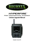
REAR PANEL
2
1
3
(1) FUSE
The unit is AC power line fuse protected from overloads and fault conditions with an ABC-type fast-blow 5
Amp fuse. This fuse is located within the cap of the fuse holder. If the fuse fails, THE FUSE MUST BE
REPLACED WITH THE SAME TYPE AND VALUE IN ORDER TO AVOID DAMAGE TO THE EQUIPMENT AND TO
PREVENT VOIDING THE WARRANTY. If the unit repeatedly blows fuses, it should be taken to a qualified
service center for repair.
(2) IEC POWER CORD CONNECTION
This receptacle is for the IEC line cord (supplied) that provides AC power to the unit.
Never break off the ground pin on any equipment. It is provided for your safety. If the outlet
used does not have a ground pin, a suitable grounding adapter should be used and the third
wire should be grounded properly. To prevent the risk of shock or fire hazard, always be sure
that the mixer and all other associated equipment are properly grounded.
(3) ON-OFF SWITCH
This rocker switch supplies AC power to the PR 10P when switched to the ON position.
5
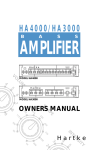
FRONT PANEL
5
6
7
4
8
9
(4) POWER/CLIP LED
Illuminates GREEN when the electronics receive power (when the Power switch (3) is On). Illuminates RED
when amplifier clipping is occurring or the unit has tripped the thermal protection system.
(5) PRIMARY INPUT (CHANNEL 1)
The primary input is switchable between line-level and mic-level input. The line-level input is of the
medium impedance balanced type, and when switched to mic-level it is of a typical low-Z mic input
impedance. Jack (5) is a combo female XLR and 1/4" TRS connector.
(6) PAD
Switches the sensitivity of Channel 1 from line-level to mic-level sensitivity. Pushed all the way in, the
sensitivity is set for line-level input signals, and when the white tab is closer to the front panel, the
sensitivity is increased by 30 dB so it is suitable for mic-level signals.
(7) VOLUME
Controls the gain (level) of the Primary Input (5), Channel 1, of the powered speaker system. It is used to
directly set the system output level for the Channel 1 input signal.
(8) SECONDARY INPUTS, CHANNEL 2 & 3
These consist of 1/4" unbalanced phone jacks for line-level signals, with medium input impedance.
(9) CONCENTRIC VOLUME, CHANNEL 2 & 3
Controls the gain (level) of Channel 2 & 3 inputs. Can be used in conjunction with the Channel 1 volume
control (7) to mix three line-level signals together, or two line-level signals and one mic-level signal.
6
OPERATING INSTRUCTIONS
CAUTIONS
The unit must be disconnected from the AC power source before any work is done on it. Refer all servicing
to qualified service personnel.
The heat sink on the back plate can become hot to the touch. Do not block or cover the heat sink from
ventilation.
Be sure to keep the microphone away from the front of the speaker after switching the mic sensitivity pad
to the OUT position and while setting the microphone level or very loud feedback will occur! Damage to
the system is likely if this occurs!
DO NOT connect the inputs of the PR™10P to the output of a power amplifier. The inputs are meant to be
driven from a line-level strength signal.
DO NOT remove the protective metal grille.
Warning: The PR 10P is very efficient and powerful! This sound system can permanently damage hearing!
Use extreme care setting the overall maximum loudness!
The apparent sound level of the PR 10P can be deceiving due to its clear, clean sound output. The lack of
distortion or obvious distress can make the sound level seem much lower than it actually is. This system is
capable of SPL in excess of 119 dB at 1 M from the speaker!
Flying the PR 10P
Caution: The suspending or flying of the Peavey PR 10P must be done by a certified structural engineer.
Important Safety Information for Mounting the Peavey PR 10P speaker system
Caution: Before attempting to suspend this model of speaker, consult a certified structural engineer.
Speaker can fall due to improper suspension, resulting in serious injury and property damage. Other
enclosures must not be suspended below one, nor should additional weight be suspended from one of
these units. Use only the correct mating hardware. All associated rigging is the responsibility of others.
Always use all four inserts of a given group as a set, NEVER use just one insert to fly a cabinet! The four
insert groupings are a top group of four and a bottom group of four. Some models also have a group of
four on the rear plane of the cabinet.
Maximum enclosure angle from vertical hang: 30˚
Always use a suitable safety chain or wire rope, looped through the top handle, and firmly attached to a
suitable structural member as indicated by a certified structural engineer.
The recommended range of torque for the mounting bolt is 3 to 3-1/2 lb./feet of torque. DO NOT
OVERTIGHTEN! If an insert spins, it has been damaged and the cabinet can not be flown!
Never transport the cabinet while mounted on an array bracket or other mounting bracket, as this may
unduly stress the mounting inserts.
WARNING! (note to structural engineer)
For the PR 10P, the thread insertion depth of the end of the mounting bolt should not be more than 5/16"
past the surface of the cabinet.
If these thread insertion depths are exceeded, then the inserts may be damaged or unseated from the
cabinet, severely compromising the mounting integrity of the cabinet!
The correct mounting bolt diameter and threads per inch are: 1/4" X 20. Use of a grade five-bolt is
recommended.
7
G e t t i n g A C P o w e r T o T h e P R ™ 10P
The PR 10P comes with an 8-foot IEC connection AC power cord. If you are using an extension cord or power
strip with this powered speaker, make sure it is of good quality and of a sufficient current capacity to maintain
safety and maximize the power output capability of the PR 10P. Do not connect any other device to the same
extension cord that the PR 10P is connected to.
Special Note for Permanent Installation
When installing the PR 10P, AC power runs will be used and a certified electrician should be consulted to
be sure that all AC wiring complies with local codes and regulations. It is also advisable to use a cable clip
properly affixed to the cabinet to strain relief the IEC power cord connected to the amplifier module at (2)
so the power cord cannot be pulled out or vibrate loose.
Use of PR 10P with a Subwoofer
The built-in pole adapter allows use with the Peavey SP Subcompact 18X and the accessory pole that it is
designed to use, Peavey part #00326540.
The pole used is 36 3/16" long and has a nominal diameter of 1 3/8".
Getting a Signal to the PR 10P
There are a variety of ways to input a signal to the PR 10P.
The primary input (5) provides either a balanced mic- or line-level input, allowing the use of a 1/4" phone
plug, either a standard single-ended (tip-sleeve) plug or a balanced TRS (tip-ring-sleeve) type plug OR a
male XLR plug. Then there are two line-level unbalanced 1/4" phone jacks that can be mixed in with the
primary input.
Do not connect cables to the jacks while the unit is ON and the Volume is turned up!
While a standard single-ended 1/4" phone plug-equipped cable will work well, and the balanced input
circuitry of the primary input (5) will provide some interference rejection, a balanced cable using either
the balanced TRS 1/4" phone plug or the XLR plug will provide superior interference rejection and
performance. Sometimes, with difficult interference problems, it will be helpful to lift the shield ground on
a balanced cable at the PR 10P end only. Check any input changes carefully, always turning the volume
control down before plugging and unplugging cables.
Use of high quality, premium cables is recommended for the PR 10P, as these usually have better
shielding and materials and will provide greater long-term reliability. It is usually a good idea to leave
some slack at the input to the PR 10P and also to tape the cables down or run them under a cable guard to
avoid anyone tripping over them or pulling the PR 10P over when stand mounted.
Volume Control Adjustment
The PR 10P is equipped with a volume control to facilitate use in many different applications. With the
volume control adjusted fully clockwise, gain is at maximum and the input sensitivity is 0.375 V RMS for
full rated output. When driving the PR 10P from a mixer, it may be advantageous to reduce the input
sensitivity by turning the volume control to the halfway point. The PR 10P will now more closely match a
typical power amp.
If the mixing board indicates clipping of it’s output signals, then all of the PR 10P power capability is not
being utilized cleanly. Clipping the signal before it gets to the PR 10P is not optimal. Reduce the mixer
output level and turn up the volume control on the PR 10P.
The amplifiers in the PR 10P are equipped with DDT™ and an LED indicator to show that DDT™ has
engaged. If the sound seems heavily compressed, check this indicator; and if it is blinking RED more than
occasionally, then the drive level from the mixer (or the volume control on the PR 10P) needs to be
reduced.
8
When first turning on the sound system, switch on all upstream electronics first, then the PR™10P with its
volume control fully counter clockwise (all the way down). Begin checking levels with the mixer output
level controls all the way down, and bring them up slowly with the PR 10P volume control set to the
desired setting (halfway up recommended to start).
Mic/Line Pad Adjustment
The mic/line pad (6) provides for the increased gain needed for microphone use into the primary input (5).
Use a straightened paperclip or small screwdriver to reach through the hole in the rear panel where the
recessed tab is to set its position. Set the Mic/Line Pad to “in,” or the white tab furthest from the panel,
for line-level signal use and set it “out,” or closest to the panel, for mic level use. The unit is shipped with
the tab in the line-level position. It is recessed behind the panel so that the gain cannot be inadvertently
increased during transport or set-up.
Due to the 30 dB of extra gain that this switch provides, DO NOT leave it in the “out” position for line-level
use! This will result in input-stage clipping of the PR 10P and cause unnecessary distortion.
Mixing Signals Using the Volume Knobs
The gain of all three channels can be adjusted independently from the other channels via the volume
knobs (7) and (9). Channel 1 can be used for either line-level signals or as a mic input and mixed with two
other line-level signals.
The PR 10P has plenty of gain, so do not overload the speaker system preamp inputs by driving them with
a signal that is too hot. Full output mixer levels well in excess of 0 dB will not be necessary to drive the
unit to full power capacity.
TROUBLESHOOTING
No Output at All
First, make sure the unit has AC power and is turned on. Make sure the Power/Clip LED (4) is illuminated Green.
If not, make certain the ON/OFF switch (3) is in the ON position and check the IEC power cord connection (2) by
ensuring it is fully engaged and seated. Make certain the AC line cord is plugged into a working AC outlet.
Finally, check the fuse (1). (See the Rear Panel: Fuse section, for safety instructions.)
Once assured your unit is getting AC power, check that the PR 10P is getting a signal. Temporarily disconnect
the cable running to the its inputs and connect it to some other device capable of reproducing the signal (i.e., a
power amp and speaker). If this produces a signal, make sure that all Volume controls being used have been
turned up to a satisfactory level (one-third to halfway).
If the PR 10P has been subjected to direct sunlight or excessive heat, the built-in thermal protection may have
been triggered. The power/clip LED will be illuminated RED if this is the case. If so, turn off the PR 10P and let it
cool for a sufficient amount of time.
If there is still no output, contact your authorized Peavey dealer or the Peavey International Service Center.
9
Hum or Buzz
If the PR™10P is producing a hum or buzz, this can be AC outlet related. Try plugging the PR 10P into a
different AC outlet. Sometimes, if a different circuit (breaker) is used for the mixer and the PR 10P, it can
cause hum problems.
Ensure that shielded cables have been used to route the signal to PR 10Ps inputs. If speaker cables with
1/4" plugs are used as input cables instead of shielded cables, it will be prone to hum or buzz.
Hum may be ground loop related. Try lifting the ground connection at the speaker end of the signal cable if
it is a balanced signal cable. Check any input changes carefully by first turning down the volume control,
plugging and unplugging cables, or lifting the shield ground at the speaker end.
Check to make sure light dimmers are not on the same circuit as the PR 10P, the mixer or any source
devices. If light dimmers are used, then it may be necessary to turn them full ON or full OFF to eliminate or
reduce hum. This is a typical AC wiring/light dimmer interference problem, and not a design flaw of the PR
10P. The third wire (ground plug) on the AC plug should NEVER be removed or broken off.
Distorted or Fuzzy Sound
First, ensure the mixer (signal source) is not clipping or being overdriven. Make sure the volume control/s
(7) and (9) on the PR 10P have not been set too low.
Check that the input plugs are fully seated in the input jacks (5) and (8) on the rear panel of the PR 10P.
Ensure that the proper MIC/LINE PAD setting is being used (6) for line-level signals, or that a power amp
has not been plugged into one of the input jacks of the PR 10P.
If an extension cord is being used to provide the AC power to the unit, ensure that it is of sufficient
current capacity and that it is not also being used to supply power to any other device.
The PR 10P has built-in EQ to extend and smooth the natural response of the speakers in the system. Bass
boost and HF EQ have been applied and the system has a nominally flat response, so it should require
little, if any, additional EQ. If excessive additional bass boost or HF boost have been added externally to
the PR 10P, it could cause premature overload at high SPL. Reducing the amount of any external (mixer,
rack) EQ and see if that clears up the distortion.
Finally, realize that even though the PR 10P is a powerful and high output unit, it does ultimately have
limits, and it may need additional powered units (or a subwoofer) to provide enough sound output or
coverage. In this case, try turning the mixer levels down a little to see if that clears things up.
If, after checking all the things listed to check and anything else you can think of to check safely, and the
system still exhibits problems, carefully note all conditions and check with your Peavey dealer for advice.
Care and Maintenance
Your PR 10P is a sturdy and durable product and will provide years of reliable use if properly cared for. Use
common sense and read the safety warnings to avoid hazardous operating conditions.
The unit must be disconnected from the AC power source before any work is done on it. Refer all servicing
to qualified service personnel.
Sunlight/Heat
Avoid prolonged exposure to direct sunlight, as this may cause the unit to overheat and thermally shut
off. Excessively hot operating conditions can also cause a thermal shutdown.
Do not store in extremely hot or cold conditions,or extremely high humidity. Always allow unit to come to
room temperature before use.
Cleaning
Never clean the PR 10P while plugged in or turned ON! When the unit has been fully disconnected from AC
power sources, use a dry cloth to remove soil or other dirt. Never use strong solvents on the PR 10P, as
they could damage the cabinet. Do not allow ANY fluids to drip inside the PR 10P.
10
Touchup
For an overall finish enhancement and protective coating, use gloves to apply a plastic finish protector,
such as Armor-All® protectant, to the surface of the plastic cabinet only. Note that the cabinet will be
slippery after these treatments, rub them down vigorously with a dry, lint-free cloth to minimize this.
Check for Secure Hardware
After the first few months of use and periodically thereafter, check the hardware of the PR 10P for
tightness, including the rear panel screws and the screws that hold the baffle and rear cabinet together.
The unit is subject to a great deal of vibration, and this could cause them loose with use.
Architectural and Engineering Specifications
The powered loudspeaker system shall have a frequency response from 67 Hz to 20 kHz. The peak SPL
with inaudible distortion shall reach 119 dB with music as a source, when measured at a distance of 1M
and driven to full output capacity. The system shall utilize a 10" heavy duty woofer and an RX™14
compression driver tweeter. The nominal radiation pattern shall be 90˚ in the horizontal plane and 40˚ in
the vertical plane.
The powered, bi-amplified loudspeaker system shall have a group of medium impedance input connectors
consisting of one combo female XLR and 1/4" TRS phone jack, and two 1/4" phone jacks, on the rear
panel. A volume control will be located near each input jack. The combo female XLR and 1/4" TRS phone
jack will have a gain adjust pad that provides for switching between line-level input signals and mic-level
input signals.
The system power amplifiers shall have an unfiltered frequency response of 10 Hz to 30 kHz which
deviates no more than +0, -1 dB up to rated power, a damping factor greater than 100 @ 1 kHz into
8 Ohms, hum and noise better than 90 dB below rated power, and THD and IMD of less than 0.1%. The
woofer amplifier shall be capable of 150 W into a 8 Ohm nominal load, and the tweeter amplifier shall be
capable of 50 W output into a 8 Ohm load, and both shall incorporate independent DDT™ compression.
The input signal shall be electronically divided into high frequencies and low frequencies by a staggeredpole third order slope line-level crossover at 2.2 kHz. The low frequencies shall be processed to provide
bass boost, subsonic filtering and overall response shaping, and the high frequencies shall be equalized
for constant directivity horn EQ- and response-shaping.
The enclosure shall be constructed of injection-molded polypropylene of 1/4" nominal thickness with a UL
flame rating, and reinforcing ribs internally. A handgrip shall be molded-in on the top rear edge.
A powder-coated metal grille shall be provided for woofer protection. The cabinet shall incorporate a pole
mount for speaker stand use, four tall sturdy rubber feet for floor standing use, and four mounting point
inserts on the top and bottom each for flying use.
The outside dimensions shall be: 18.88" tall (17.63" rear) by x 14.00" wide (8.25" in rear) by x 13.13"
deep, and the weight shall be 37 lbs. Power requirements shall be: 100 Watts nominal, 120 VAC, 60 Hz
Domestic and 240 VAC, 50 Hz (European). The loudspeaker system shall be called a Peavey PR 10P.
11
Peavey PR™10P
SPECIFICATIONS
Enclosure: Peavey PR 10P (domestic)
Frequency response:
67 Hz to 20 kHz
Low frequency limit (-3 dB point):
67 Hz
Useable low frequency limit (-10 dB
point):
55 Hz
Internal power amplifiers (@120 VAC
line):
Woofer - 200 Watts peak dynamic
power
150 Watts @ less than 0.1% distortion
Tweeter - 70 Watts peak dynamic power
50 Watts @ less than 0.1% distortion.
Nominal sensitivity (1W @1M, swept
sine input in anechoic environment):
95 dB
Maximum sound pressure level:
119 dB music peak
Nominal radiation angles:
90˚ horizontal by 40˚ vertical
Transducer complement:
10" heavy duty woofer and RX™14 1.4"
titanium diaphragm compression driver
tweeter
Box tuning frequency (Fbox):
76 Hz
Electroacoustic crossover frequency:
2,200 Hz
Crossover type:
Internal Electronic two-way crossover
with CD horn EQ, level matching, bass
boost and subsonic filtering.
Crossover Slopes:
18 dB/octave (third order) low pass,
18 dB/octave (third order) high pass,
both with staggered poles and driver
EQ. Unit has horn spatially aligned
with woofer, so there is no need for
phase alignment or time delay of the
signals.
Electronic Input Impedance (Nominal):
10 k Ohms unbalanced, 20 k Ohms
balanced line level, 2.4 k Ohms
balanced mic level.
Input Connections:
One combo female XLR/ 1/4" phone
jack providing balanced operation, with
switch selectable mic or line level
sensitivity. Also has two 1/4" phone
jack line level unbalanced inputs with a
concentric pair of level controls.
Additional remarks:
Also available as a passively crossedover unit, the Peavey PR 10.
ELECTRONICS AND AMPLIFIER
SPECIFICATIONS:
Electronic input impedance (nominal):
Primary balanced input: 20 k Ohms line
level sensitivity selected, 2.4 k Ohms
mic level sensitivity selected, 10 k
Ohms unbalanced 1/4."
Mic switch sensitivity Increase:
30 dB
Infrasonic filter protection:
36 dB/octave roll-off
Nominal amplifier frequency response:
+0, -1 dB from 10 Hz to 30 kHz
Enclosure materials and finish:
Injection-molded polypropylene of a
nominal thickness of 1/4" with internal
ribbing and bracing, and with textured
finish. Molded material is dark gray
Hum and noise:
Greater than 90 dB below rated power
Mounting:
Subwoofer pole-mounting via moldedin mount, flying via Versamount™ 35
(top or bottom of cabinet) or the newer
Versamount™ 70 (with extra mounting
holes in the Versamount™ 35 pattern),
and 4 rubber feet for floor use.
THD and IM:
Typically less than 0.1 %
Dimensions:
18.88" (47.9 cm) tall {17.63" /44.8 cm
in rear} by 14.00" (35.6 cm) wide
{8.25"/21.0 cm in rear} by 13.13"
(33.3 cm) deep
Optional accessories:
Impulse® 100 Floor Monitor Kit
(FG# 00454130)
Net weight:
37 lbs.
12
DDT dynamic range:
Greater than 14 dB
Damping factor:
Greater than 100 @ 1000 Hz, 8 Ohms
Power requirements of Peavey PR™12P
system (domestic):
Nominal 100 Watts, 120 VAC, 60 Hz
FREQUENCY RESPONSE CURVES
Amplitude Response (1m On-Axis)
dB SPL (re 20 Pa)
110
100
90
80
70
60
20
Figure 1
50
100
200
500
1k
Frequency (Hz)
13
2k
5k
10k
20k
DEUTSCH
PR ™ 10P
Wir möchten uns bei Ihnen dafür bedanken, dass Sie sich für die Power-Ausführung der Pro-Lite-Serie PR™12 entschieden
haben. Der PR 10P ist mit zwei Endstufen ausgestattet, die 200 Watt dynamische Spitzenleistung für den Woofer und 70
Watt dynamische Spitzenleistung für den Hochtöner mit Kompressionstreiber – beide mit Peaveys exklusiver DDT ™Schutzschaltung – liefert. Der PR 10P ist nicht nur mit einem 10" Heavy-Duty-Woofer und dem RX™14Kompressionstreiber ausgestattet, sondern bietet zudem eine XLR- und eine 6,3-mm-Kopfhörer-Combo-Klinke,
zuschaltbare symmetrierte Mikro- und Line-Pegeleingänge mit Lautstärkeregelung sowie ein Paar 6,3-mmKopfhörerklinken-Eingänge mit konzentrischen Lautstärkereglern. Es können bis zu drei Line-Pegeleingangssignale oder
ein Mic-Pegel- und zwei Line-Pegelsignale miteinander gemischt werden.
Der PR 10P darf nur mit der korrekten Wechselstromnetzspannung gespeist werden. Die korrekte Spannung für Ihren
PR 10P ist neben dem IEC-Netzkabel auf der Rückseite des Geräts aufgedruckt. Lesen Sie sich diese Anleitung bitte
sorgfältig durch, damit sowohl Ihre Sicherheit als auch die Ihrer Ausrüstung gewährleistet ist.
Merkmale
· Power-System mit zwei Endstufen mit insgesamt 270 W dynamischer Spitzenleistung!
· Beide Endstufen sind mit DDT-Schutzschaltung ausgestattet
· 10"-Heavy-Duty-Woofer mit 2"-Schwingspule und 1,4-kg-Magnet
· 1,4" RX14-Kompressionstreiber aus Titan
· Spitzenschalldruckpegel von bis zu 119 dB bei Musik!
· Combo-Klinke mit 6,3-mm-TRS-Stecker und XLR-Stecker weiblich für symmetrierte Mic- oder Line-Pegeleingänge
· Zwei 6,3-mm-Kopfhörerklinkeneingänge mit konzentrischen Pegelreglern
· Eingebaute Eingangsmischung
· Eingegossenes Horn mit herausragendem gleichmäßigem Ansprechen und Klangverteilung
· Handgriffe oben und an den Seiten
· Eingebautes Ständermontagesystem
· Flugpunkteinsätze oben und unten
Beschreibung
Der Peavey PR 10P ist ein Zweiwege-Power-Lautsprechersystem mit zwei Endstufen, das entwickelt wurde, um mit einem
kompakten Power-Lautsprecher ein Höchstmaß an Leistung zu erbringen. Dieses kleine System, das einen
Spitzenschalldruckpegel von bis zu 119 dB liefert, zeichnet sich durch seine enorme Soundleistung aus. Die Box besteht
aus hartem Spritzguss-Polypropylen in Trapezform sowie einem beschichteten Stahlgitter, sodass Sie ein attraktives und
dennoch robustes Power-Lautsprechersystem vor sich haben.
Dieses Zweiwege-Power-System besteht aus einer Endstufe mit einer dynamischen Spitzenleistung von 200 W, die einen
12"-Heavy-Duty-Woofer treibt. Der RX™14-Kompressionstreiber wird über eine Endstufe mit einer dynamischen
Spitzenleistung von 70 W getrieben und ist mit einer 1,4"-Titanmembran ausgestattet, die an ein extrem gleichmäßiges
und gut kontrolliertes Constant-Directivity-Horn (mit einem Abstrahlwinkel von 90° mal 40°) angeschlossen ist, das in die
Box eingegossen ist.
Beim symmetrierten Eingang zur Vorverstärker- bzw. EQ-Elektronik handelt es sich um einen Combo-XLR-Stecker weiblich
und eine 6,3-mm-TRS-Kopfhörerklinke. Die Eingangsempfindlichkeit lässt sich zwischen Mic-Pegel und Line-Pegel
umschalten. Zwei 6,3-mm-Kopfhörerklinkeneingänge werden mit einem konzentrischen Paar von Pegelreglern geregelt.
Alle drei Eingänge können in jedem beliebigen Verhältnis gemischt werden.
14
Bei den zwei integrierten Endstufen handelt es sich um verzerrungsarme Geräte, die 150 W RMS
Continuous an 8 Ohm Woofer-Nennlast und 50 W RMS Continuous an 8 Ohm Hochtöner-Nennlast bringen.
Sie wurden auf Grund ihrer Zuverlässigkeit und hervorragenden Eigenschaften und Leistungsfähigkeit im
Musikbereich ausgewählt. Beide Verstärker sind mit unserer patentierten DDT™-Schutzschaltung
ausgestattet, die nahezu jedes hörbare Endstufen-Clipping ausschaltet.
Der eingegossene Griff erleichtert den Transport, und durch mehrere Montagepunkte (oben und unten) für
den Peavey Versamount™ wird die Einsatzfähigkeit noch gesteigert.
Einsatzbereiche
Der Peavey PR™10P eignet sich für eine Vielzahl von Einsatzbereichen wie etwa Beschallung, PA-Anlagen,
Ergänzungssysteme, Karaoke oder Musik-Playback. Mit einem als Zubehör erhältlichen MonitorständerBausatz lässt sich der PR 10P in einen hervorragenden Bühnenmonitor umwandeln.
Eine typische Signalquelle für die Line-Pegeleingänge des Peavey PR 10P wären etwa ein
Beschallungsanlagen-Mischpult oder der Ausgang eines CD-Players, Minidisc-Players oder Tonbandgeräts.
Auch ein dynamisches Mikro kann angeschlossen und eingesetzt werden.
RÜCKEN VERTIEFTES
2
1
3
(1) SICHERUNG
Das Gerät ist durch eine flinke ABC-Sicherung (5 Ampere) vor Überlastungen und Störungen gesichert
(Wechselstrom-Netzanschluss). Diese Sicherung befindet sich im Deckel der Sicherungsfassung. Sollte die
Sicherung durchbrennen, MUSS SIE DURCH EINE SICHERUNG DERSELBEN ART UND MIT DENSELBEN
WERTEN ERSETZT WERDEN, UM EINE BESCHÄDIGUNG DER GERÄTE UND EINEN VERFALL DER GARANTIE
ZU VERMEIDEN. Sollte die Sicherung des Geräts wiederholt durchbrennen, muss es zu einem qualifizierten
Servicecenter zur Reparatur gebracht werden.
(2) ANSCHLUSS DES IEC-NETZKABELS
In diese Steckdose wird das beiliegende IEC-Netzkabel gesteckt, über das das Gerät mit Wechselstrom
versorgt wird.
Der Erdungsstift darf in keinem Fall an irgendeinem Gerät entfernt werden. Er ist zu Ihrer Sicherheit
vorhanden. Fehlt der Erdungsstift bei der verwendeten Steckdose, muss ein geeigneter Erdungsadapter
verwendet und die dritte Ader korrekt geerdet werden. Um die Gefahr eines elektrischen Schlags oder
eines Brands zu verhindern, müssen das Mischpult sowie alle anderen zugehörigen Ausrüstungsteile
korrekt geerdet werden.
(3) EIN/AUS-SCHALTER
Steht dieser Schalter auf der Position ON, wird der PR 10P mit Wechselstrom versorgt.
15
FRONT PANEL
5
6
7
4
8
9
(4) POWER/CLIP-LED
Diese LED leuchtet grün, wenn die Elektronik mit Strom versorgt wird bzw. wenn der Power-Schalter (3) auf ON
steht. Sie leuchtet rot, wenn Verstärker-Clipping vorliegt oder der Thermoschutz des Geräts ausgelöst hat.
(5) PRIMARY INPUT (CHANNEL 1)
Der Haupteingang lässt sich zwischen Line-Pegeleingang und Mic-Pegeleingang umschalten. Der LinePegeleingang ist mittelohmig und symmetriert, und beim Umschalten auf Mic-Pegel wird er in einen typischen
niederohmigen Mikroeingang umgewandelt. Bei Klinke (5a) handelt es sich um einen Combo-XLR-Stecker
weiblich und einen 6,3-mm-Klinkenstecker.
(6) PAD
Hiermit wird die Empfindlichkeit von Kanal 1 zwischen Line-Pegel und Mic-Pegel umgeschaltet. Bei vollständig
eingedrücktem Schalter wird die Empfindlichkeit für Line-Pegeleingangssignale eingestellt; liegt der weiße
Streifen näher an der Frontblende, wird die Empfindlichkeit um 30 dB erhöht, sodass sie für Mic-Pegelsignale
geeignet ist.
(7) VOLUME
Mit diesem Regler wird die Verstärkung (Pegel) des Haupteingangs (5), Kanal 1, des PowerLautsprechersystems geregelt. Er wird zur direkten Einstellung des Systemausgangspegels für das
Eingangssignal von Kanal 1 verwendet.
(8) SECONDARY INPUTS, CHANNEL 2 und 3
Die Nebeneingänge sind unsymmetrierte 6,3-mm-Kopfhörerklinken für Line-Pegelsignale mit mittlerer
Eingangsimpedanz.
(9) CONCENTRIC VOLUME, CHANNEL 2 und 3
Regelt die Verstärkung (Pegel) der Eingänge von Kanal 2 und 3. Er kann zusammen mit dem Lautstärkeregler (7)
von Kanal 1 eingesetzt werden, um drei Line-Pegelsignale oder zwei Line-Pegelsignale und ein Mic-Pegelsignal
zusammenzumischen.
16
BETRIEBSANLEITUNG
VORSICHTSMAßNAHMEN
Bevor irgendwelche Arbeiten am Gerät durchgeführt werden, muss es von der Wechselstromquelle
getrennt werden. Lassen Sie sämtliche Wartungsarbeiten von qualifizierten Kundendiensttechnikern
durchführen.
Der Kühlkörper an der Rückwand kann heiß werden, daher darf er nicht berührt werden. Der Kühlkörper
darf nicht blockiert oder abgedeckt werden, da ansonsten die Belüftung beeinträchtigt wird.
Achten Sie darauf, dass Sie das Mikro nach dem Umschalten des Mic-Sensitivity-Schalters auf OUT und
während des Einpegelns des Mikros nicht vor den Lautsprecher halten, da es ansonsten ein sehr lautes
Feedback gibt! In diesem Fall wird das System beschädigt!
Schließen Sie die Eingänge des PR™10P NICHT an den Ausgang einer Endstufe an. Die Eingänge sind so
ausgelegt, dass sie von einem Signal mit Line-Pegelstärke getrieben werden müssen.
Entfernen Sie NICHT das metallene Schutzgitter.
Achtung: Der PR 10P ist äußerst kraftvoll und leistungsfähig! Der Einsatz dieses Systems kann zu
dauerhaften Hörschäden führen! Stellen Sie die maximale Gesamtlautstärke daher mit äußerster Vorsicht
ein!
Der Eindruck hinsichtlich des Schallpegels des PR 10P kann auf Grund seiner klaren, sauberen
Klangwiedergabe täuschen. Da kaum Verzerrung vorhanden ist und die Lautstärke nicht als unangenehm
empfunden wird, scheint der Schallpegel wesentlich geringer zu sein als er tatsächlich ist. Dieses System
ist in der Lage, einen Schalldruckpegel von über 119 dB in einer Entfernung von einem Meter vom
Lautsprecher zu liefern!
Fliegen des PR 10P
Achtung: Das Aufhä ngen oder Fliegen des Peavey PR 10P muss von einem zugelassenen Bauingenieur
durchgeführt werden.
Wichtige Sicherheitsinformationen für die Montage des Peavey PR 10P-Lautsprechersystems:
Achtung: Bevor Sie versuchen, dieses Lautsprechermodell aufzuhängen, muss ein zugelassener
Bauingenieur zu Rate gezogen werden. Wird der Lautsprecher nicht korrekt aufgehängt, kann er
herunterfallen und schwerwiegende Personen- und Sachschäden verursachen. Es dürfen keine Boxen
untereinander aufgehängt werden, und es dürfen keine zusätzlichen Lasten an diese Geräte gehängt
werden. Es dürfen nur die korrekten, geeigneten Beschlagteile verwendet werden. Sämtliche zugehörigen
Montagearbeiten fallen unter die Verantwortung Dritter.
Es müssen immer alle vier Einsatzteile eines vorhandenen Sets zusammen verwendet werden. Zum Fliegen
einer Box darf NIE nur ein einziges Einsatzteil verwendet werden. Bei den vier Einsatzteil-Sets handelt es
sich um ein oberes und ein unteres Set von jeweils vier Teilen. Einige Modelle verfügen zudem über ein
Set von vier Einsatzteilen auf der Rückseite der Box.
Der maximale Winkel zur vertikalen Aufhängung der Box beträgt 30°.
Verwenden Sie immer eine geeignete Sicherheitskette oder ein geeignetes Drahtseil. Diese müssen durch
den oberen Griff geführt und fest an einem geeigneten Bauteil befestigt werden, wie von einem
zugelassenen Bauingenieur angewiesen.
Der empfohlene Drehmoment für Montagebolzen beträgt 4-4,75 Nm. ZIEHEN SIE SIE NICHT ZU FEST AN!
Dreht ein Einsatzteil durch, ist es beschädigt, und die Box kann nicht aufgehängt werden!
Transportieren Sie die Box nie auf einen Gruppenträger oder einen anderen Montageträger montiert, da
dies die Montageeinsätze übermäßig strapazieren könnte.
17
ACHTUNG! (Anmerkung für den Bauingenieur)
Beim PR 10P darf die Gewindeeinsatztiefe des Endes des Montagebolzens nicht über 8 mm hinter der
Außenfläche der Box betragen.
Werden diese Gewindeeinsatztiefen überschritten, können die Einsatzteile beschädigt oder aus der Box
gelöst werden, wodurch eine sichere Montage der Box schwerwiegend beeinträchtigt wird.
Der korrekte Durchmesser von Montagebolzen und Gewinde pro Zoll beträgt 1/4" x 20. Es wird ein Bolzen
Größe 5 empfohlen.
Versorgung des PR ™10P mit Wechselstrom
Der PR 10P wird mit einem IEC-Anschlussnetzkabel (Wechselstrom) von ca. 2,40 m Länge geliefert. Verwenden
Sie für diesen Power-Lautsprecher nur Verlängerungskabel oder Mehrfachsteckdosen von guter Qualität und
ausreichender Stromkapazität, sodass die Sicherheit gewährleistet ist und der PR 10P eine optimale Leistung
bringt. Es darf kein anderes Gerät an das Verlängerungskabel angeschlossen werden, an das der PR 10P
angeschlossen ist.
Besondere Hinweise für die Dauerinstallation
Verwenden Sie zur Installation des PR 10P Wechselstromleitungen, und ziehen Sie einen zugelassenen
Elektriker zu Rate um zu gewährleisten, dass die gesamte Wechselstromverdrahtung den örtlichen
Vorschriften entspricht. Daneben empfiehlt es sich, das in die Verstärkerbuchse (2) eingesteckte IECNetzkabel mit einer Kabelklemme an der Box zu befestigen, um den Zug zu entlasten, sodass es nicht
herausgezogen werden oder sich durch Vibrationen lösen kann.
Einsatz des PR 10P mit einem Subwoofer
Der eingebaute Ständeradapter ermöglicht den Einsatz mit dem Peavey SP Subcompact 18X; der als
Zubehör erhältliche geeignete Ständer hat die Peavey-Teilenummer 00326540.
Der verwendete Mast hat eine Länge von ca. 90 cm und einen Nenndurchmesser von 3 cm.
Senden von Signalen an den PR 10P
Es gibt eine Vielzahl von Möglichkeiten, Signale an den PR 10P zu senden.
Der Haupteingang (5) liefert einen symmetrierten Mic- bzw. Line-Pegeleingang und erlaubt so den Einsatz
eines 6,3-mm-Kopfhörersteckers, entweder eines genormten unsymmetrierten Klinkensteckers (TS) oder
eines symmetrierten Klinkensteckers (TRS) ODER eines männlichen XLR-Steckers. Daneben gibt es zwei
unsymmetrierte 6,3-mm-Kopfhörerklinken für Line-Pegelsignale, die dem Haupteingang zugemischt
werden können.
Schließen Sie die Kabel nie an die Klinken an, wenn das Gerät eingeschaltet und die Lautstärke
aufgedreht ist!
Ein Kabel mit genormtem unsymmetriertem 6,3-mm-Kopfhörerstecker ist zwar gut geeignet, und der
symmetrierte Eingangsschaltkreis des Haupteingangs (5) bietet auch gewissen Schutz gegen
Störgeräusche, ein symmetriertes Kabel mit symmetriertem 6,3-mm-Kopfhörerklinkenstecker oder der
XLR-Stecker bieten jedoch einen wesentlich besseren Schutz gegen Störgeräusche sowie eine
herausragende Leistung. Bestehen schwerwiegende Probleme mit Störgeräuschen, sollten Sie versuchen,
die Erdung an einem symmetrierten Kabel am zum PR 10P zeigenden Ende anzuheben. Überprüfen Sie
sorgfältig sämtliche Eingangsveränderungen und drehen Sie vor dem Einstecken und Abziehen von Kabeln
immer den Lautstärkeregler herunter.
18
Für den PR 10P werden qualitativ hochwertige Kabel empfohlen, da bei diesen in der Regel Abschirmung
und Material besser sind und sie eine längere Haltbarkeit und Zuverlässigkeit gewährleisten. Empfohlen
wird auch, am Eingang zum PR 10P einen gewissen Spielraum zu lassen und die Kabel abzukleben oder sie
unter einem Kabelschutz zu verlegen, sodass niemand darüber stolpert oder den PR 10P am Kabel
herabzieht, wenn er auf einem Ständer montiert ist.
Einstellen des Lautstärkereglers
Der PR 10P ist mit einem Lautstärkeregler ausgestattet, der den Einsatz in den verschiedensten
Situationen erleichtert. Ist der Lautstärkeregler vollständig im Uhrzeigersinn aufgedreht, ist die
Verstärkung maximal, und die Eingangsempfindlichkeit beträgt 0,375 V RMS für die volle Nennleistung.
Wird der PR 10P über ein Mischpult betrieben, kann es von Vorteil sein, die Eingangsempfindlichkeit zu
verringern, indem der Lautstärkeregler auf die Hälfte heruntergedreht wird. Der PR 10P arbeitet nun noch
mehr wie eine typische Endstufe.
Zeigt das Mischpult ein Clipping seiner Ausgangssignale an, wird nicht das gesamte Leistungsvermögen
des PR 10P sauber genutzt. Ein Clipping des Signals, bevor es zum PR 10P gelangt, sollte vermieden
werden. Verringern Sie in diesem Fall den Ausgangspegel des Mischpults, und drehen Sie den
Lautstärkeregler des PR 10P herauf.
Die Verstärker des PR 10P sind mit der DDT™-Schutzschaltung ausgestattet, wobei anhand einer LEDAnzeige ersichtlich ist, ob diese Funktion aktiviert wurde. Hört sich der Sound deutlich verdichtet an, muss
diese Anzeige überprüft werden. Leuchtet sie häufiger auf, muss der Drive-Pegel vom Mischpult (oder der
Lautstärkeregler am PR 10P) herabgedreht werden.
Wird das Beschallungssystem zu ersten Mal eingeschaltet, muss zuerst die gesamte vorgeschaltete
Elektronik eingeschaltet werden und dann erst der PR 10P, wobei sein Lautstärkeregler vollständig im
entgegengesetzten Uhrzeigersinn (herunter) gedreht werden muss. Beginnen Sie mit der Überprüfung der
Pegel mit vollständig herabgedrehten Mischpult-Ausgangspegelreglern, und drehen Sie sie langsam
herauf, wobei der Lautstärkeregler des PR 10P auf der gewünschten Einstellung steht (für den Anfang wird
empfohlen, ihn auf die Hälfte heraufzudrehen).
Einstellen des Mic/Line-Schalters
Der Mic/Line-Schalter (6) liefert den höheren Gain an den Haupteingang (5), der für den Einsatz von
Mikros erforderlich ist. Verwenden Sie eine gerade gebogene Büroklammer oder einen kleinen
Schraubenzieher, um durch die Öffnung auf der Rückseite den eingelassenen Schalter einzustellen. Rasten
Sie den Mic/Line-Schalter für Line-Pegelsignale ein (der weiße Streifen ist weit von der Blende entfernt),
und rasten Sie ihn für Mic-Pegelsignale aus (ganz nah an der Blende). Das Gerät wird ab Werk mit der
Einstellung Line-Pegel versandt. Da der Schalter hinter der Blende eingelassen ist, ist eine versehentliche
Erhöhung des Gains beim Transport oder Aufbau nicht möglich.
Da dieser Schalter eine zusätzliche Verstärkung von 30 dB liefert, darf er für Line-Pegelsignale NICHT in
der ausgerasteten Position belassen werden! Folge wären Clipping des PR 10P auf der Eingangsstufe und
unnötige Verzerrung.
Mischen von Signalen über die Lautstärkeregler
Die Verstärkung aller drei Kanäle kann unabhängig von den anderen Kanälen über die Lautstärkeregler (7)
und (9) erfolgen. Kanal 1 kann für Line-Pegelsignale oder als Mikroeingang verwendet und mit zwei
anderen Line-Pegelsignalen gemischt werden.
Der PR 10P verfügt über ein hohes Maß an Verstärkung. Vermeiden Sie daher eine Überlastung der
Vorverstärkereingänge des Lautsprechersystems, indem Sie sie mit einem zu starken Signal treiben. Zum
Treiben des Geräts mit vollständiger Kapazität sind volle Mischpult-Ausgangspegel von über 0 dB unnötig.
19
FEHLERSUCHE
Keine Ausgangsleistung
Überprüfen Sie zunächst, ob das Gerät mit Wechselstrom versorgt wird und eingeschaltet ist. Stellen Sie sicher,
dass die Power/Clip-LED (4) grün leuchtet. Ist dies nicht der Fall, überprüfen Sie, ob der ON/OFF-Schalter (3)
auf ON steht und ob das IEC-Netzkabel (2) vollständig eingesteckt ist. Das Wechselstromnetzkabel muss in eine
funktionierende Wechselstromsteckdose eingesteckt sein. Überprüfen Sie schließlich die Sicherung (1). (Siehe
Abschnitt Sicherung auf der Rückseite für Sicherheitsanweisungen).
Wenn Sie sichergestellt haben, dass der PR 10P mit Wechselstrom versorgt wird, überprüfen Sie, ob er Signale
bekommt. Ziehen Sie das Kabel ab, das in die Geräteeingänge eingesteckt ist, und schließen Sie es an ein
anderes Gerät an, das das Signal wiedergeben kann, z.B. eine Endstufe mit Lautsprecher. Ist ein Signal
vorhanden, überprüfen Sie, ob alle verwendeten Lautstärkeregler ausreichend hochgedreht sind (um etwa ein
Drittel bis die Hälfte).
Falls der PR 10P direkter Sonneneinstrahlung oder zu starker Hitze ausgesetzt war, hat womöglich sein
Thermoschutz ausgelöst. In diesem Fall leuchtet die Power/Clip-LED ROT. Ist dies der Fall, schalten Sie den PR
10P aus, und lassen Sie ihn ausreichend lange abkühlen.
Erfolgt noch immer keine Ausgangsleistung, wenden Sie sich an Ihren Peavey-Händler oder an das Peavey
International Service Center.
Brummen oder Summen
Ist aus dem PR 10P ein Brummen oder Summen zu hören, könnte dies mit der Wechselstromsteckdose
zusammenhängen. Schließen Sie den PR 10P versuchsweise an eine andere Wechselstrom-Steckdose an.
Wird für das Mischpult ein anderer Schaltkreis bzw. Überlastschalter verwendet als für den PR 10P, kann
dies Probleme durch Brummen verursachen.
Stellen Sie sicher, dass für die Signalleitung an die Eingänge des PR 10P geschirmte Kabel verwendet
werden. Werden anstatt geschirmten Kabeln Lautsprecherkabel mit 6,3-mm-Steckern als Eingangskabel
verwendet, kann dies vermehrt Brummen oder Summen verursachen.
Brummprobleme können durch Brummschleifen verursacht werden. Handelt es sich um ein symmetriertes
Signalkabel, heben Sie versuchsweise den Erdungsanschluss am Lautsprecherende des Signalkabels an.
Überprüfen Sie sorgfältig sämtliche Eingangsveränderungen. Drehen Sie dazu zunächst den
Lautstärkeregler herunter, stecken Sie die Kabel ein bzw. ziehen Sie sie ab oder heben Sie die Erdung am
zum Lautsprecher zeigenden Ende an.
Stellen Sie sicher, dass keine Licht-Dimmer an denselben Schaltkreis wie der PR 10P, das Mischpult oder
andere Quellgeräte angeschlossen sind. Werden Licht-Dimmer verwendet, müssen sie eventuell vollständig
auf- oder abgedreht werden, um das Brummen zu beseitigen oder zu reduzieren. Hierbei handelt es sich um
ein typisches, durch die Wechselstromverdrahtung bzw. den Licht-Dimmer verursachtes Problem und nicht
um eine Störung des PR 10P. Der dritte Leiter (Erdungsstecker) im Wechselstromstecker darf NIE entfernt
oder abgebrochen werden.
Verzerrter oder verschwommener Sound
Überprüfen Sie zunächst, dass beim Mischpult (Signalquelle) kein Clipping oder Übersteuern vorliegt.
Achten Sie darauf, dass die Lautstärkeregler (7) und (9) am PR 10P nicht zu niedrig eingestellt ist.
Achten Sie darauf, dass die Eingangsstecker fest in die Eingangsklinken (5) und (8) auf der Rückseite des
PR 10P eingesteckt sind. Stellen Sie sicher, dass für die Line-Pegelsignale die korrekte Einstellung des
MIC/LINE PAD verwendet wird und dass nicht versehentlich eine Endstufe an eine der Eingangsklinken des
PR 10P angeschlossen wurde.
20
Wird zur Wechselstromversorgung des Geräts ein Verlängerungskabel verwendet, muss überprüft werden,
ob seine Stromkapazität ausreichend ist und es nicht auch zur Stromversorgung weiterer Geräte
verwendet wird.
Der PR 10P ist mit einem eingebauten EQ ausgestattet, um das natürliche Ansprechen der Lautsprecher im
System zu erweitern und auszugleichen. Anhebung der Bässe und EQ der Höhen sind vorhanden, und das
System weist ein flaches Ansprechen auf und sollte – wenn überhaupt – nur wenig zusätzlichen EQ
erfordern. Wurden die Bässe oder Höhen für den PR 10P extern zusätzlich zu stark angehoben, kann dies
bei hohen Schalldruckpegeln zu einer verfrühten Überlastung führen. Verringern Sie den externen EQ
(Mischpult, Rack) um zu sehen, ob dies die Verzerrung beseitigt.
Schließlich müssen Sie sich bewusst sein, dass der PR 10P zwar ein äußerst kraftvolles und hochleistungsfähiges Gerät ist, er jedoch auch seine Grenzen hat und möglicherweise weitere Power-Geräte (oder
ein Subwoofer) erforderlich sind, um eine ausreichende Schallleistung oder Schallabstrahlung zu erzielen.
Versuchen Sie in diesem Fall, die Mischpultpegel ein wenig herunterzuregeln, um einen klareren Sound zu
erzielen.
Sollten Sie sämtliche aufgeführten Punkte sowie weitere Möglichkeiten im Rahmen der Sicherheit
überprüft haben und dennoch weitere Probleme mit dem System auftreten, notieren Sie sich bitte
sorgfältig sämtliche Bedingungen und wenden Sie sich an Ihren Peavey-Händler um Unterstützung.
Pflege und Wartung
Ihr PR 10P ist ein robustes und langlebiges Produkt, das bei sorgfältiger Pflege über lange Jahre
zuverlässig seinen Dienst tut. Hören Sie auf Ihren gesunden Menschenverstand, und lesen Sie sich die
Sicherheitshinweise durch, um gefährliche Betriebssituationen zu vermeiden.
Bevor irgendwelche Arbeiten am Gerät durchgeführt werden, muss es von der Wechselstromquelle
getrennt werden. Lassen Sie sämtliche Wartungsarbeiten von qualifizierten Kundendiensttechnikern
durchführen.
Sonnenlicht bzw. Hitze
Setzen Sie das Gerät nicht für längere Zeit direktem Sonnenlicht aus, da dies Überhitzung und
Abschaltung durch den Überhitzungsschutz zur Folge haben kann. Ein Betrieb bei übermäßiger Hitze kann
ebenfalls zur Abschaltung durch den Überhitzungsschutz führen.
Lagern Sie das Gerät nicht bei extremer Hitze oder Kälte oder extrem hoher Feuchtigkeit. Warten Sie vor
dem Einsatz des Geräts immer, bis es Raumtemperatur erreicht hat.
Reinigung
Reinigen Sie den PR 10P nie, solange er ans Netz angeschlossen oder eingeschaltet ist! Wenn das Gerät
vollständig von Wechselstromanschlüssen abgetrennt ist, können Sie Schmutz, Staub und dergleichen mit
einem trockenen Tuch entfernen. Verwenden Sie zur Reinigung des PR 10P nie starke Reinigungsmittel, da
diese die Box angreifen könnten. Achten Sie darauf, dass KEINE Flüssigkeiten in den PR 10P gelangen!
Pflege der Oberfläche
Zur Verstärkung der gesamten Beschichtung und als Schutz können Sie mit Handschuhen ein Schutzmittel
für Kunststoffflächen wie Armor-All® auf die Box auftragen (nur auf die Kunststofffläche). Da die Box nach
einer solchen Behandlung rutschig ist, muss sie mit einem fusselfreien Tuch kräftig trockengerieben
werden.
Überprüfung der Sicherheit der Beschlagteile
Nach den ersten Einsatzmonaten und auch regelmäßig danach muss überprüft werden, ob die
Beschlagteile des PR 10P fest angezogen sind, so etwa die Schrauben auf der Rückseite und die
Schrauben, die Schallwand und hintere Box zusammenhalten. Da das Gerät in hohem Maß Vibrationen
ausgesetzt ist, können sich diese Teile mit der Zeit lösen.
21
Bauliche und technische Spezifikationen
Das Power-Lautsprechersystem weist ein Frequenzverhalten von 67 Hz bis 20 kHz auf. Der
Spitzenschalldruckpegel mit unhörbarer Verzerrung erreicht bei Musik als Quelle 119 dB, gemessen in
einer Entfernung von einem Meter und mit vollständiger Leistungsfähigkeit. Das System arbeitet mit einem
10" Heavy-Duty-Woofer und einem RX™14-Kompressionstreiber-Hochtöner. Das Nennstrahlungsdiagramm
beträgt 90° in horizontaler Ebene und 40° in vertikaler Ebene.
Das Power-Lautsprechersystem mit zwei Verstärkern verfügt über eine Gruppe von mittelohmigen
Eingangssteckern, bei denen es sich um einen Combo-XLR-Stecker weiblich und einen 6,3-mm-TRSKopfhörerklinkenstecker sowie zwei 6,3-mm-Kopfhörerklinken handelt, die sich auf der Rückseite
befinden. Neben jeder Eingangsklinke befindet sich ein Lautstärkeregler. Combo-XLR-Stecker weiblich und
6,3-mm-TRS-Kopfhörerklinke verfügen über einen Schalter zur Einstellung der Verstärkung, mit dem
zwischen Line- und Mic-Pegeleingangssignalen umgeschaltet werden kann.
Die Systemendstufen verfügen über ein ungefiltertes Frequenzverhalten von 10 Hz bis 30 kHz, das um
nicht mehr als +0 abweicht, und weisen -1 dB bis Nennleistung, einen Dämpfungsfaktor von über 100 bei
1 kHz an 8 Ohm, ein Brumm- und Rauschverhalten besser als 90 dB unter Nennleistung sowie einen
Klirrfaktor und Intermodulation von unter 0,1% auf. Der Woofer-Verstärker bringt eine Leistung von 150 W
an 8 Ohm Nennlast, der Hochtöner-Verstärker bringt 50 W an 8 Ohm Nennlast, und beide verfügen über
eine unabhängige DDT™-Schutzschaltung.
Das Eingangssignal wird durch eine Line-Pegelfrequenzweiche 3. Grades mit versetztem Pol bei 2,2 kHz
elektronisch in Höhen und Tiefen geteilt. Die Tiefen werden bearbeitet, um Anhebung der Bässe, SubsonicFilterung und allgemeine Bearbeitung des Ansprechverhaltens zu bieten, und die Höhen werden
abgeglichen, um EQ des CD-Horns und Bearbeitung des Ansprechverhaltens zu bieten.
Die Box ist aus spritzgussgeformtem Polypropylen mit einer Nennstärke von 6,3 mm mit einer ULFlammbeständigkeit und internen Verstärkungsrippen gefertigt. Auf jeder Seite des Woofers und an der
oberen hinteren Kante ist ein Handgriff eingegossen.
Zum Schutz des Woofers ist ein vinylbeschichtetes Metallgitter vorhanden. Die Box ist mit einem
eingebauten Ständermontagesystem, vier großen robusten Gummifüßen zum Abstellen auf dem Boden
und jeweils vier Montagepunkt-Einsatzteilen oben und unten für den Einsatz im Flugsystem ausgestattet.
Die Außenmaße betragen 48 cm (Höhe) x 36 cm (45 cm hinten) (Breite) x 35 cm (Tiefe), das Gewicht
beträgt 16,7 kg. Der Leistungsbedarf beträgt: Nominal 100 Watt, 120 V Wechselstrom, 60 Hz (USA) und
240 V Wechselstrom, 50 Hz (Europa). Das Lautsprechersystem trägt die Bezeichnung Peavey PR 10P.
22
Peavey PR™10P
SPEZIFIKATIONEN
Enclosure: Peavey PR 10P (domestic)
Frequency response:
67 Hz to 20 kHz
Low frequency limit (-3 dB point):
67 Hz
Useable low frequency limit (-10 dB
point):
55 Hz
Internal power amplifiers (@120 VAC
line):
Woofer - 200 Watts peak dynamic
power
150 Watts @ less than 0.1% distortion
Tweeter - 70 Watts peak dynamic power
50 Watts @ less than 0.1% distortion.
Nominal sensitivity (1W @1M, swept
sine input in anechoic environment):
95 dB
Maximum sound pressure level:
119 dB music peak
Nominal radiation angles:
90˚ horizontal by 40˚ vertical
Transducer complement:
10" heavy duty woofer and RX™14 1.4"
titanium diaphragm compression driver
tweeter
Box tuning frequency (Fbox):
76 Hz
Electroacoustic crossover frequency:
2,200 Hz
Crossover type:
Internal Electronic two-way crossover
with CD horn EQ, level matching, bass
boost and subsonic filtering.
Crossover Slopes:
18 dB/octave (third order) low pass,
18 dB/octave (third order) high pass,
both with staggered poles and driver
EQ. Unit has horn spatially aligned
with woofer, so there is no need for
phase alignment or time delay of the
signals.
Electronic Input Impedance (Nominal):
10 k Ohms unbalanced, 20 k Ohms
balanced line level, 2.4 k Ohms
balanced mic level.
Input Connections:
One combo female XLR/ 1/4" phone
jack providing balanced operation, with
switch selectable mic or line level
sensitivity. Also has two 1/4" phone
jack line level unbalanced inputs with a
concentric pair of level controls.
Additional remarks:
Also available as a passively crossedover unit, the Peavey PR 10.
ELECTRONICS AND AMPLIFIER
SPECIFICATIONS:
Electronic input impedance (nominal):
Primary balanced input: 20 k Ohms line
level sensitivity selected, 2.4 k Ohms
mic level sensitivity selected, 10 k
Ohms unbalanced 1/4."
Mic switch sensitivity Increase:
30 dB
Infrasonic filter protection:
36 dB/octave roll-off
Nominal amplifier frequency response:
+0, -1 dB from 10 Hz to 30 kHz
Enclosure materials and finish:
Injection-molded polypropylene of a
nominal thickness of 1/4" with internal
ribbing and bracing, and with textured
finish. Molded material is dark gray
Hum and noise:
Greater than 90 dB below rated power
Mounting:
Subwoofer pole-mounting via moldedin mount, flying via Versamount™ 35
(top or bottom of cabinet) or the newer
Versamount™ 70 (with extra mounting
holes in the Versamount™ 35 pattern),
and 4 rubber feet for floor use.
THD and IM:
Typically less than 0.1 %
Dimensions:
18.88" (47.9 cm) tall {17.63" /44.8 cm
in rear} by 14.00" (35.6 cm) wide
{8.25"/21.0 cm in rear} by 13.13"
(33.3 cm) deep
Optional accessories:
Impulse® 100 Floor Monitor Kit
(FG# 00454130)
Net weight:
37 lbs.
23
DDT dynamic range:
Greater than 14 dB
Damping factor:
Greater than 100 @ 1000 Hz, 8 Ohms
Power requirements of Peavey PR™12P
system (domestic):
Nominal 100 Watts, 120 VAC, 60 Hz
ESPAÑOL
PR ™ 10P
Gracias por adquirir la versión amplificada del PR™ 10P de la serie Pro-Lite. El PR 10P Cuenta con una sección de biamplificación que genera 200 Watts de poder dinámico máximo para el woofer y 70 Watts de poder dinámico máximo
para el driver de compresión del tweeter, ambos con la compresión exclusiva de Peavey DDT™. Ofreciendo un woofer de
12" de alto rendimiento y el driver de compresión RX™, el PR 10P cuenta con un conectador combo de XLR y de 1/4", nivel
intercambiable entre micrófono/línea, entrada balanceada con control de volumen, y un par de entradas de 1/4" con
controles de volumen concéntricos. Se pueden mezclar hasta tres señales de entrada de nivel de línea, o mezclar una
señal de nivel de micrófono y dos de nivel de línea.
Es muy importante asegurarse que el PR 10P cuenta con el voltaje de línea de CA adecuado. Puedes encontrar el voltaje
adecuado para tu PR 10P impreso junto al cable de corriente IEC en el panel trasero de la unidad. Por favor lee esta guía
con cuidado para asegurar tu seguridad personal y la de tu equipo.
Características
· Sistema bi-amplificado con 270 W de poder total
· Compresión DDT para prevenir saturación en ambos amplificadores
· Woofer de alto rendimiento de 10" con imán de 50 oz. y rollo de 2"
· Driver de compresión de titanio RX 14 de 1.4"
· Nivel de presión sonora arriba de 119 dB con música
· Entrada de combo balanceada TRS de 1/4 y XLR Femenina de nivel de línea o micrófono
· Dos entradas de 1/4" tipo plug con controles de nivel concéntricos.
· Entrada de mezcla integrada
· Corneta moldeada con respuesta súper suave y control de modelo
· Agarraderas a los lados y parte superior
· Entrada para atril integrada
· Puntos de inserción para volarla en la parte superior e inferior
Descripción
El PR 12P de Peavey es un sistema de parlantes de dos vías biamplificado diseñado para brindar altos niveles de
ejecución en un parlante amplificado compacto. Capaz de generar niveles de presión sonora de hasta 119 SPL, este
pequeño sistema puede generar mucho sonido. La unidad está hecha de polipropileno moldeado en una forma
trapezoidal con una rejilla de metal para ofrecer un sistema de parlantes tanto atractivo como durable.
Este sistema amplificado de dos vías incluye un amplificador con capacidad máxima de 200 W alimentando un woofer de
alto rendimiento de 12". El driver de compresión RX™ 14 es alimentado por el amplificador de 70 Watts de poder máximo
y cuanta con un diafragma de titanio de 1.4" con una corneta de dirección (con una capacidad de cobertura de 90° por
40°) moldeada de manera integral en el parlante.
Una entrada balanceada al preamplificador/electrónicos del EQ consiste de una entrada combo de XLR femenina y 1/4"
TRS tipo plug. Es intercambiable entre sensibilidad de nivel de línea y nivel de micrófono. Dos entradas de 1/4" tipo plug
son controladas por un par de controles de nivel concéntricos. Las tres entradas pueden ser mezcladas a cualquier razón.
Los amplificadores de poder que generan la biamplificación son unidades de baja distorsión que proveen 150 W
continuos RMS a una carga nominal de 8 ohmios al woofer, y 50 W continuos RMS a una carga de 8 ohmios para el
tweeter. Fueron seleccionados por su durabilidad y su capacidad superior de ejecución musical. Ambos amplificadores
cuentan con nuestra compresión patentada DDT™, que elimina virtualmente la saturación audible del amplificador.
Una agarradera integrada provee facilidad de transporte, mientras que múltiples puntos de montura (arriba y abajo)
Versamount™ de Peavey brindan máxima utilidad.
24
Aplicaciones
El PR™ 10P de Peavey cuenta con una Amplia gama de aplicaciones como sonido en vivo, sistemas de
voceo, side fills, karaoke o reproducción musical. Con el paquete opcional de atril para monitor, el PR 10P
de Peavey es un excelente monitor de escenario.
Una típica señal de nivel de línea en las entradas del PR 10P de Peavey sería una mezcladora (consola) o
la salida de un reproductor de CD, MiniDisc o reproductor de cintas. Un micrófono dinámico también
puede ser conectado y usado a la vez.
PANEL TRASERO
2
1
3
(1) FUSIBLE
La unidad está protegida de sobrecargas de corriente CA con un fusible de resolución rápida tipo ABC de 5
Amperes. Este fusible está localizado en la tapa del receptáculo para fusible. Si el fusible falla, DEBE SER
REEMPLAZADO POR UNO DEL MISMO TIPO Y CAPACIDAD PARA PREVENIR DAÑOS AL EQUIPO Y PARA PREVENIR
LA CANCELACIÓN DE LA GARANTÍA. Si la unidad continua votando el FUSIBLE debe ser verificada por un técnico
de servicio calificado.
(2) CONEXIÓN PARA CABLE DE CORRIENTE IEC
El cable de corriente IEC (incluido) se conecta a este receptáculo para proveer corriente a la unidad.
Nunca se debe quitar la aguja de tierra de ningún equipo. Ha sido incluido para tu seguridad. Si la fuente de
corriente no cuenta con una entrada para esta aguja, se debe usar un adaptador y la tercera aguja debe quedar
propiamente aterrizada. Para prevenir el riesgo de una descarga eléctrica, hay que asegurarse que la
mezcladora y todo el demás equipo asociado está propiamente aterrizado.
(3) INTERRUPTOR DE ENCENDIDO/APAGADO
Este interruptor aplica corriente al PR 10P cuando se pone en la posición de encendido (ON).
25
PANEL FRONTAL
5
6
7
4
8
9
(4) LED DE ENCENDIDO/SATURACIÓN
Este se ilumina VERDE cuando los electrónicos del amplificador reciben corriente, (cuando el interruptor
de encendido (3) está en la posición de encendido ON). Se lumina en ROJO cuando el amplificador está
experimentando saturación o la unidad entra en modo de protección térmica.
(5) ENTRDA PRIMARIA (CANAL 1)
La entrada primaria en intercambiable entre nivel de línea y nivel de micrófono. La entrada de nivel de
línea es de impedancia media, y cuando se selecciona el nivel de micrófono es una entrada típica de
micro Low-Z de baja impedancia. El conectador es un combo XLR femenino y 1/4" TRS tipo plug.
(6) PAD
Cambia la sensibilidad del Canal 1 de nivel de línea a nivel de micrófono. Si se aprieta al fondo, la
sensibilidad está en la posición de impedancia media balanceada, y cuando la parte blanca está más
cerca del panel frontal, la sensibilidad se incrementa a 30 dB para poder manejar señales de nivel de
micrófono.
(7) VOLUMEN
Controla LA Ganancia (nivel) de la Entrada Primaria (5), Canal 1, del sistema de parlantes. Se usa para
ajustar directamente el nivel de salida del sistema de la señal de entrada del Canal 1.
(8) ENTRADAS SECUNDARIAS, CANALES 2 Y 3
Estas consisten de entradas de 1/4" no balanceadas para señales de nivel de línea, con impedancia de
entrada media.
(9) VOLUMEN CONCÉNTRICO, CANALES 2 Y 3
Controla la ganancia (nivel) de las entradas de los canales 2 y 3. Puede ser usada en conjunto con el
control de volumen del Canal 1 (7) para mezclar tres señales de nivel de línea, o dos de nivel de línea y
una de micrófono.
26
INSTRUCCIONES DE OPERACIÓN
PRECAUCIONES
Esta unidad debe ser desconectada de la toma de corriente CA antes de realizar cualquier trabajo en ella.
Todo servicio debe ser llevado a cabo por personal calificado.
La trampa de calor en la parte trasera puede estar caliente al tacto. Nunca se debe cubrir o bloquearle la
ventilación.
Asegúrate de mantener el micrófono lejos de la parte frontal del parlante después de encender la entrada
del micro, y durante el ajuste de nivel el mismo, o se puede crear retroalimentación severa. Es muy
posible que el equipo sufra daños si esto llegara a suceder.
NUNCA se deben conectar las entradas del PR™ 10P a la salida de un amplificador. Las entradas han sido
diseñadas para ser alimentadas por señales de nivel de línea.
NUNCA quites la rejilla metálica de protección
CUIDADO: : El PR 10P es extremadamente poderoso y eficiente. Este sistema de sonido puede dañar tus
oídos permanentemente. Se debe usar máxima precaución cuando se ajusten los volúmenes máximos.
El nivel de sonido aparente del PR 10P puede ser engañoso dada su calidad y limpieza en el sonido. La
falta de distorsión puede hacer que el nivel de sonido parezca más bajo de lo que está. Este sistema es
capaz de producir niveles de presión sónica (SPL) encima de los 119 dB a 1 M del parlante.
VOLANDO EL PR 10P
Cuidado: El suspender o volar las PR 10P de Peavey es un proceso que debe ser llevado a cabo por un
ingeniero certificado.
Información importante de montaje del sistema de parlantes PR 10P de Peavey
Cuidado: Antes de intentar suspender este modelo de parlantes, consulta a un ingeniero de estructuras
calificado. Los parlantes se pueden caer de suspensiones incorrectas, resultando en daños al equipo y
personales. Otros sistemas no pueden ser suspendidos debajo de uno, o tampoco se debe añadir peso
adicional a las unidades. Usa solamente equipos de instalación adecuados. Todo lo asociado con la
instalación de las unidades es responsabilidad de otros.
Siempre hay que usar los cuatro insertos de un grupo como conjunto, NUNCA se use sólo un inserto para
volar una unidad. Los grupos de insertos son uno de cuatro en la parte superior, otro de cuatro en la parte
inferior y algunos modelos cuentan con otro grupo de cuarto en la parte trasera de la unidad.
El ángulo máximo para colgar verticalmente es de 30º
Siempre se debe usar una cadena o cuerda metálica, amarrada del asa superior, y esta debe estar
propiamente instalada a una estructura firme como lo indique un ingeniero capacitado.
La presión de tornillo para el tornillo de montura es de 3 pies a 3 pies 1/2 por libra. NO SE SOBRE
APRIETE. Si uno de los insertos da vueltas, ha sido dañado y la unidad no podrá ser volada.
Nunca se debe transportar la unidad mientras está montada. Esto puede causar seria presión en las
piezas y en los insertos.
ATTENTION! (note aux ingénieurs de structures)
For the PR 10P, the thread insertion depth of the end of the mounting bolt should not be more than 5/16"
past the surface of the cabinet.
If these thread insertion depths are exceeded, then the inserts may be damaged or unseated from the
cabinet, severely compromising the mounting integrity of the cabinet!
The correct mounting bolt diameter and threads per inch are: 1/4" X 20. Use of a grade five-bolt is
recommended.
27
G e t t i n g A C P o w e r T o T h e P R ™ 10P
The PR 10P comes with an 8-foot IEC connection AC power cord. If you are using an extension cord or power
strip with this powered speaker, make sure it is of good quality and of a sufficient current capacity to maintain
safety and maximize the power output capability of the PR 10P. Do not connect any other device to the same
extension cord that the PR 10P is connected to.
Special Note for Permanent Installation
When installing the PR 10P, AC power runs will be used and a certified electrician should be consulted to
be sure that all AC wiring complies with local codes and regulations. It is also advisable to use a cable clip
properly affixed to the cabinet to strain relief the IEC power cord connected to the amplifier module at (2)
so the power cord cannot be pulled out or vibrate loose.
Use of PR 10P with a Subwoofer
The built-in pole adapter allows use with the Peavey SP Subcompact 18X and the accessory pole that it is
designed to use, Peavey part #00326540.
The pole used is 36 3/16" long and has a nominal diameter of 1 3/8".
Getting a Signal to the PR 10P
There are a variety of ways to input a signal to the PR 10P.
The primary input (5) provides either a balanced mic- or line-level input, allowing the use of a 1/4" phone
plug, either a standard single-ended (tip-sleeve) plug or a balanced TRS (tip-ring-sleeve) type plug OR a
male XLR plug. Then there are two line-level unbalanced 1/4" phone jacks that can be mixed in with the
primary input.
Do not connect cables to the jacks while the unit is ON and the Volume is turned up!
While a standard single-ended 1/4" phone plug-equipped cable will work well, and the balanced input
circuitry of the primary input (5) will provide some interference rejection, a balanced cable using either the
balanced TRS 1/4" phone plug or the XLR plug will provide superior interference rejection and
performance. Sometimes, with difficult interference problems, it will be helpful to lift the shield ground on
a balanced cable at the PR 10P end only. Check any input changes carefully, always turning the volume
control down before plugging and unplugging cables.
Use of high quality, premium cables is recommended for the PR 10P, as these usually have better shielding
and materials and will provide greater long-term reliability. It is usually a good idea to leave some slack at
the input to the PR 10P and also to tape the cables down or run them under a cable guard to avoid anyone
tripping over them or pulling the PR 10P over when stand mounted.
Volume Control Adjustment
The PR 10P is equipped with a volume control to facilitate use in many different applications. With the
volume control adjusted fully clockwise, gain is at maximum and the input sensitivity is 0.375 V RMS for
full rated output. When driving the PR 10P from a mixer, it may be advantageous to reduce the input
sensitivity by turning the volume control to the halfway point. The PR 10P will now more closely match a
typical power amp.
If the mixing board indicates clipping of it’s output signals, then all of the PR 10P power capability is not
being utilized cleanly. Clipping the signal before it gets to the PR 10P is not optimal. Reduce the mixer
output level and turn up the volume control on the PR 10P.
The amplifiers in the PR 10P are equipped with DDT™ and an LED indicator to show that DDT™ has engaged.
If the sound seems heavily compressed, check this indicator; and if it is blinking RED more than
occasionally, then the drive level from the mixer (or the volume control on the PR 10P) needs to be
reduced.
28
When first turning on the sound system, switch on all upstream electronics first, then the PR™10P with its
volume control fully counter clockwise (all the way down). Begin checking levels with the mixer output
level controls all the way down, and bring them up slowly with the PR 10P volume control set to the
desired setting (halfway up recommended to start).
Mic/Line Pad Adjustment
The mic/line pad (6) provides for the increased gain needed for microphone use into the primary input (5).
Use a straightened paperclip or small screwdriver to reach through the hole in the rear panel where the
recessed tab is to set its position. Set the Mic/Line Pad to “in,” or the white tab furthest from the panel,
for line-level signal use and set it “out,” or closest to the panel, for mic level use. The unit is shipped with
the tab in the line-level position. It is recessed behind the panel so that the gain cannot be inadvertently
increased during transport or set-up.
Due to the 30 dB of extra gain that this switch provides, DO NOT leave it in the “out” position for line-level
use! This will result in input-stage clipping of the PR 10P and cause unnecessary distortion.
Mixing Signals Using the Volume Knobs
The gain of all three channels can be adjusted independently from the other channels via the volume
knobs (7) and (9). Channel 1 can be used for either line-level signals or as a mic input and mixed with two
other line-level signals.
The PR 10P has plenty of gain, so do not overload the speaker system preamp inputs by driving them with
a signal that is too hot. Full output mixer levels well in excess of 0 dB will not be necessary to drive the
unit to full power capacity.
TROUBLESHOOTING
No Output at All
First, make sure the unit has AC power and is turned on. Make sure the Power/Clip LED (4) is illuminated Green.
If not, make certain the ON/OFF switch (3) is in the ON position and check the IEC power cord connection (2) by
ensuring it is fully engaged and seated. Make certain the AC line cord is plugged into a working AC outlet.
Finally, check the fuse (1). (See the Rear Panel: Fuse section, for safety instructions.)
Once assured your unit is getting AC power, check that the PR 10P is getting a signal. Temporarily disconnect
the cable running to the its inputs and connect it to some other device capable of reproducing the signal (i.e., a
power amp and speaker). If this produces a signal, make sure that all Volume controls being used have been
turned up to a satisfactory level (one-third to halfway).
If the PR 10P has been subjected to direct sunlight or excessive heat, the built-in thermal protection may have
been triggered. The power/clip LED will be illuminated RED if this is the case. If so, turn off the PR 10P and let it
cool for a sufficient amount of time.
If there is still no output, contact your authorized Peavey dealer or the Peavey International Service Center.
Hum or Buzz
If the PR™10P is producing a hum or buzz, this can be AC outlet related. Try plugging the PR 10P into a
different AC outlet. Sometimes, if a different circuit (breaker) is used for the mixer and the PR 10P, it can
cause hum problems.
Ensure that shielded cables have been used to route the signal to PR 10Ps inputs. If speaker cables with
1/4" plugs are used as input cables instead of shielded cables, it will be prone to hum or buzz.
29
Hum may be ground loop related. Try lifting the ground connection at the speaker end of the signal cable if
it is a balanced signal cable. Check any input changes carefully by first turning down the volume control,
plugging and unplugging cables, or lifting the shield ground at the speaker end.
Check to make sure light dimmers are not on the same circuit as the PR 10P, the mixer or any source
devices. If light dimmers are used, then it may be necessary to turn them full ON or full OFF to eliminate or
reduce hum. This is a typical AC wiring/light dimmer interference problem, and not a design flaw of the PR
10P. The third wire (ground plug) on the AC plug should NEVER be removed or broken off.
Distorted or Fuzzy Sound
First, ensure the mixer (signal source) is not clipping or being overdriven. Make sure the volume control/s
(7) and (9) on the PR 10P have not been set too low.
Check that the input plugs are fully seated in the input jacks (5) and (8) on the rear panel of the PR 10P.
Ensure that the proper MIC/LINE PAD setting is being used (6) for line-level signals, or that a power amp
has not been plugged into one of the input jacks of the PR 10P.
If an extension cord is being used to provide the AC power to the unit, ensure that it is of sufficient current
capacity and that it is not also being used to supply power to any other device.
The PR 10P has built-in EQ to extend and smooth the natural response of the speakers in the system. Bass
boost and HF EQ have been applied and the system has a nominally flat response, so it should require
little, if any, additional EQ. If excessive additional bass boost or HF boost have been added externally to
the PR 10P, it could cause premature overload at high SPL. Reducing the amount of any external (mixer,
rack) EQ and see if that clears up the distortion.
Finally, realize that even though the PR 10P is a powerful and high output unit, it does ultimately have
limits, and it may need additional powered units (or a subwoofer) to provide enough sound output or
coverage. In this case, try turning the mixer levels down a little to see if that clears things up.
If, after checking all the things listed to check and anything else you can think of to check safely, and the
system still exhibits problems, carefully note all conditions and check with your Peavey dealer for advice.
Care and Maintenance
Your PR 10P is a sturdy and durable product and will provide years of reliable use if properly cared for. Use
common sense and read the safety warnings to avoid hazardous operating conditions.
The unit must be disconnected from the AC power source before any work is done on it. Refer all servicing
to qualified service personnel.
Sunlight/Heat
Avoid prolonged exposure to direct sunlight, as this may cause the unit to overheat and thermally shut off.
Excessively hot operating conditions can also cause a thermal shutdown.
Do not store in extremely hot or cold conditions,or extremely high humidity. Always allow unit to come to
room temperature before use.
Cleaning
Never clean the PR 10P while plugged in or turned ON! When the unit has been fully disconnected from AC
power sources, use a dry cloth to remove soil or other dirt. Never use strong solvents on the PR 10P, as
they could damage the cabinet. Do not allow ANY fluids to drip inside the PR 10P.
Touchup
For an overall finish enhancement and protective coating, use gloves to apply a plastic finish protector,
such as Armor-All® protectant, to the surface of the plastic cabinet only. Note that the cabinet will be
slippery after these treatments, rub them down vigorously with a dry, lint-free cloth to minimize this.
30
Check for Secure Hardware
After the first few months of use and periodically thereafter, check the hardware of the PR 10P for
tightness, including the rear panel screws and the screws that hold the baffle and rear cabinet together.
The unit is subject to a great deal of vibration, and this could cause them loose with use.
Architectural and Engineering Specifications
The powered loudspeaker system shall have a frequency response from 67 Hz to 20 kHz. The peak SPL
with inaudible distortion shall reach 119 dB with music as a source, when measured at a distance of 1M
and driven to full output capacity. The system shall utilize a 10" heavy duty woofer and an RX™14
compression driver tweeter. The nominal radiation pattern shall be 90˚ in the horizontal plane and 40˚ in
the vertical plane.
The powered, bi-amplified loudspeaker system shall have a group of medium impedance input connectors
consisting of one combo female XLR and 1/4" TRS phone jack, and two 1/4" phone jacks, on the rear
panel. A volume control will be located near each input jack. The combo female XLR and 1/4" TRS phone
jack will have a gain adjust pad that provides for switching between line-level input signals and mic-level
input signals.
The system power amplifiers shall have an unfiltered frequency response of 10 Hz to 30 kHz which
deviates no more than +0, -1 dB up to rated power, a damping factor greater than 100 @ 1 kHz into
8 Ohms, hum and noise better than 90 dB below rated power, and THD and IMD of less than 0.1%. The
woofer amplifier shall be capable of 150 W into a 8 Ohm nominal load, and the tweeter amplifier shall be
capable of 50 W output into a 8 Ohm load, and both shall incorporate independent DDT™ compression.
The input signal shall be electronically divided into high frequencies and low frequencies by a staggeredpole third order slope line-level crossover at 2.2 kHz. The low frequencies shall be processed to provide
bass boost, subsonic filtering and overall response shaping, and the high frequencies shall be equalized
for constant directivity horn EQ- and response-shaping.
The enclosure shall be constructed of injection-molded polypropylene of 1/4" nominal thickness with a UL
flame rating, and reinforcing ribs internally. A handgrip shall be molded-in on the top rear edge.
A powder-coated metal grille shall be provided for woofer protection. The cabinet shall incorporate a pole
mount for speaker stand use, four tall sturdy rubber feet for floor standing use, and four mounting point
inserts on the top and bottom each for flying use.
The outside dimensions shall be: 18.88" tall (17.63" rear) by x 14.00" wide (8.25" in rear) by x 13.13"
deep, and the weight shall be 37 lbs. Power requirements shall be: 100 Watts nominal, 120 VAC, 60 Hz
Domestic and 240 VAC, 50 Hz (European). The loudspeaker system shall be called a Peavey PR 10P.
31
Peavey PR™10P
ESPECIFICACIONES
Enclosure: Peavey PR 10P (domestic)
Frequency response:
67 Hz to 20 kHz
Low frequency limit (-3 dB point):
67 Hz
Useable low frequency limit (-10 dB
point):
55 Hz
Internal power amplifiers (@120 VAC
line):
Woofer - 200 Watts peak dynamic
power
150 Watts @ less than 0.1% distortion
Tweeter - 70 Watts peak dynamic power
50 Watts @ less than 0.1% distortion.
Nominal sensitivity (1W @1M, swept
sine input in anechoic environment):
95 dB
Maximum sound pressure level:
119 dB music peak
Nominal radiation angles:
90˚ horizontal by 40˚ vertical
Transducer complement:
10" heavy duty woofer and RX™14 1.4"
titanium diaphragm compression driver
tweeter
Box tuning frequency (Fbox):
76 Hz
Electroacoustic crossover frequency:
2,200 Hz
Crossover type:
Internal Electronic two-way crossover
with CD horn EQ, level matching, bass
boost and subsonic filtering.
Crossover Slopes:
18 dB/octave (third order) low pass,
18 dB/octave (third order) high pass,
both with staggered poles and driver
EQ. Unit has horn spatially aligned
with woofer, so there is no need for
phase alignment or time delay of the
signals.
Electronic Input Impedance (Nominal):
10 k Ohms unbalanced, 20 k Ohms
balanced line level, 2.4 k Ohms
balanced mic level.
Input Connections:
One combo female XLR/ 1/4" phone
jack providing balanced operation, with
switch selectable mic or line level
sensitivity. Also has two 1/4" phone
jack line level unbalanced inputs with a
concentric pair of level controls.
Additional remarks:
Also available as a passively crossedover unit, the Peavey PR 10.
ELECTRONICS AND AMPLIFIER
SPECIFICATIONS:
Electronic input impedance (nominal):
Primary balanced input: 20 k Ohms line
level sensitivity selected, 2.4 k Ohms
mic level sensitivity selected, 10 k
Ohms unbalanced 1/4."
Mic switch sensitivity Increase:
30 dB
Infrasonic filter protection:
36 dB/octave roll-off
Nominal amplifier frequency response:
+0, -1 dB from 10 Hz to 30 kHz
Enclosure materials and finish:
Injection-molded polypropylene of a
nominal thickness of 1/4" with internal
ribbing and bracing, and with textured
finish. Molded material is dark gray
Hum and noise:
Greater than 90 dB below rated power
Mounting:
Subwoofer pole-mounting via moldedin mount, flying via Versamount™ 35
(top or bottom of cabinet) or the newer
Versamount™ 70 (with extra mounting
holes in the Versamount™ 35 pattern),
and 4 rubber feet for floor use.
THD and IM:
Typically less than 0.1 %
Dimensions:
18.88" (47.9 cm) tall {17.63" /44.8 cm
in rear} by 14.00" (35.6 cm) wide
{8.25"/21.0 cm in rear} by 13.13"
(33.3 cm) deep
Optional accessories:
Impulse® 100 Floor Monitor Kit
(FG# 00454130)
Net weight:
37 lbs.
32
DDT dynamic range:
Greater than 14 dB
Damping factor:
Greater than 100 @ 1000 Hz, 8 Ohms
Power requirements of Peavey PR™12P
system (domestic):
Nominal 100 Watts, 120 VAC, 60 Hz
FRANÇAIS
PR ™ 10P
Merci d’avoir choisi la version amplifiée de la PR™10. La PR™10 possède une section bi-amplification lui fournissant 200
watts peak pour le haut-parleur et 70 Watts peak pour le moteur de compression, tous deux munis du système de
protection Peavey DDT™. Equipée d’un haut-parleur de 10" et du moteur de compression RX™14, la PR™10 offre des
entrées micro et ligne symétriques ainsi qu’un contrôle de volume.
Il est important de vérifier que votre unité est compatible avec la source d’alimentation électrique. Les caractéristiques
des besoins de votre enceinte sont annotées à côté du connecteur IEC (connecteur pour cordon d’alimentation). Merci
également de lire ce guide attentivement pour votre propre sécurité ainsi que celle de votre matériel.
Caractéristiques
· Système bi-amplifié d’une puissance totale de 270 W!
· Système de protection DDT sur les deux amplis de puissance
· Haut-parleur de 10" à bobine de 2-3/8"(60mm)
· Moteur de compression 1.4" titanium RX™14
· Sensibilité de sortie Peak SPL à plus de 119 dB!
· Entrées lignes asymétriques Jack 1/4" TS
· Entrée séparée microphone XLR ou Jack mâle
· Système de mixage incorporé
· Moteur de compression monté sur trompe procurant une réponse douce et controlable
· Adaptateur pour monte sur pied d’enceinte ou pole.
· Poignées multiples
· Points de fixation sur les faces inférieures et supérieures
Description
La Peavey PR 10P est une enceinte deux-voies bi-amplifiée d’une grande puissance et compacité. Permettant d’atteindre
des pressions acoustiques de 119 dB SPL en crête, cette petite enceinte moulée en polypropylène est néanmoins légère à
la vue de ses performances.
Ce système 2-voies est composé d’un amplificateur de 200 Watts (Peak – Dynamique) alimentant un haut-parleur 12"
professionnel. Le moteur de compression RX™14 est alimenté par un amplificateur de 70 Watts (Peak – Dynamique). Il est
muni d’une membrane 1.4" titanium et est monté sur une trompe à directivité permettant une diffusion de 90˚ x 40˚.
L’entrée symétrique du préampli est de type combo XLR/Jack femelle. La sensibilité de cette entrée peut être atténuée
pour s’accomoder à la fois d’un signal de niveau ligne ou microphone. Deux Jack d’entrée additionnelle ont leur
sensibilité contrôlée par un double potentiomètre concentriaue. Les trois entrées peuvent être utilisées simultanément et
mixées indépendamment.
Les amplificateurs de puissance fournissent 150W RMS sous 8 Ohm (charge du haut-parleur 12") et 50W RMS sous 8
Ohm (charge du moteur de compression). Le haut-parleur et le moteur de compression ont été sélectionné pour leur
excellente reproduction du signal, alors que les amplificateurs sont tout deux munis du système de protection DDT™ qui
élimine toute coupure du signal(clipping).
De multiples poignées moulées facilitent le transport, les divers points de montage (faces supérieures et inférieures)
permettent d’adapter aisément une attache Peavey Versamount™, et un adaptateur pour perche est moulé pour faire face
à toutes les applications.
33
Applications
Les PR™12P sont adaptées à de très nombreuses applications, telles que karaoke, conférence, diffusion de
musique,... De plus, vous pouvez grace à l’adaptateur ‘Monitor Stand’ la transformer en un retour de scène
amplifié.
Vous pouvez y envoyer aussi bien un signal de sortie de console de mixage, de lecteur CD (ou autre) ou
d’un micro.
PANNEAU ARRIERE
2
1
3
(1) FUSIBLE
Votre unité est protégée contr tout problème de surtension/sur-alimentation par un fusible de type ABC
standard de 5 Amp. Ce fusible est localisé dans le support de fusible. Si le fusible grille, IL DOIT ETRE
REMPLACE PAR UN FUSIBLE DE MEME CARACTERISTIQUES POUR EVITER TOUT DOMMAGE A VOTRE
MATERIEL. Si le fusible grille de facon répétitive, elle devrait être vérifiée par un technicien qualifié.
(2) CONNECTEUR IEC
Connectez ici le cordon d’alimentation de l’appareil.
Ne jamais déconnecter ou omettre une bonne connection à la terre pour votre unité. Si
l’alimentation électrique n’est pas équipée de prise de terre, un adaptateur pourra être
utilisé et le connecteur de terre relié à la terre proprement. Assurez-vous aue tous les
élèments de votre système sont correctement rlié à la terre pour éviter toute décharge
électrique.
(3) INTERRUPTEUR ON-OFF
Cette interrupteur met l’appareil sous-tension en position "I".
34
PANNEAU AVANT
5
6
7
4
8
9
(4) POWER/CLIP LED
Cette LED s’illumine en vert pour indiquer que votre unité est sous tension (interrupteur 3 en position
ON). Elle s’illumine en rouge pour indiquer le dépassement de la limite d’écrètage ou la mise en sécurité
thermique.
(5) PRIMARY INPUT (ENTREE CANAL 1)
Cette entrée est dite primaire – elle s’accomode de presque tous les types de signaux (micro, niveau
ligne,…). Elle est équipée d’un pad d’atténuation pour permettre le meilleur rendu quelque soit le signal.
Son connecteur est dit Combo femelle car il accepte à la fois une XLR ou un Jack mâle.
(6) PAD
Cet atténuateur vous permet de contrôler la sensibilité d’entrée du canal correspondant (canal1) entre
‘niveau ligne’ et ‘niveau microphone’. Enfoncé, l’atténuateur est en position ‘niveau ligne’. En position
sortie, l’atténuateur est en position ‘niveau microphone’ et l’entrée correspondante dispose de 30 dB
supplémentaire de sensibilité.
(7) VOLUME
Contrôle le niveau de l’entrée primaire (5) du canal 1 de votre unité, utilisé pour contrôler le niveau de
sortie de votre unité.
(8) SECONDARY INPUTS (ENTREE CANAUX 2 & 3)
Ces entrées assymétriques en Jack vous permettent d’envoyer 1 ou 2 sigaux de niveau ligne à votre unité.
(9) CONCENTRIC VOLUME (CONTROLE DE VOLUME DES CANAUX 2 & 3)
Ce potentiomètre concentrique vous permet d’ajuster le niveau des signaux des entrées 2 & 3. Il peut être
utilisé en conjonction avec le controle de volume du canal 1 pour ‘mixer’ les trois signaux ensemble
(Canal 1, Canal 2 & Canal 3).
35
MANUEL D’UTILISATION
ATTENTION
Votre unité doit être disconnectée de sa source d’alimentation électrique avant d’entreprendre tout travail
de maintenance sur celle-ci. Référez-vous à un technicien pour l’entretien de votre unité.
The heat sink on the back plate can become hot to the touch. Do not block or cover the heat sink from
ventilation.
Le radiateur de la plaque arrière peut atteindre des températures élevées. Veillez à ne pas obstruer ou
couvrir ces radiateurs.
Assurez-vous de gardez le microphone à l’écart de la facade de votre unité aprés que l’interrupteur de
mise en route de celui-ci soit enclenché et pendant la balance de celui-ci afin de prévenir tout effet de
Larsen.
NE CONNECTEZ PAS LES ENTREES DE VOTRE PR™ 10P AUX SORTIES D’UN AMPLI DE PUISSANCE. Ces
entrées sont prévues pour recevoir un signal de niveau ligne.
N’ENLEVEZPAS LA GRILLE DE PROTECTION METAL.
ATTENTION: : La PR™ 10P est un système efficace et puissant! Il peut facilement endommager l’oreille
humaine. Soyez prudent pendant les réglages de volume de votre unité.
Si vous êtes décu par les performances de votre PR™ 10P, n’oubliez pas que le signal très clair et net de
votre enceinte portera par sa dynamique. Prenez du recul! Ce système est capable d’un rendement de plus
de 119 dB.
Suspendre la PR 10P
ATTENTION: Suspendre des enceintes doit être supervisé par un personnel qualifié.
Informations importantes pour suspendre une Peavey PR 10P
Attention: Consultez un ingénieur du batiment (Stucture) avant tout! Une mauvaise installation peut
résulter en la chute d’une enceinte, pouvant entrainer de graves accidents et détruire du matériel.
Toujours utilisez du matériel de suspension adéquate. Ne jamais suspendre des enceintes en dessous les
unes des autres. Ne jamais ajouter de poids supplémentaires à une enceinte.
Toujours utilisez les systèmes de fixations au complet. Ne jamais suspendre une enceintes grace à un
système d’attache incomplet.
Angle maximum en suspension : 30o (Par rapport à la Vertical)
Toujours utiliser un système de sécurité, une chaine ou corde solide, attachée à la poignée principale de
votre unité et à un élément structurel comme indiqué par un personnel qualifié.
Les couples de serrages recommandés sont compris entre 0,75 et 0,90 m.kg. NE SERRER PAS TROP les
anneaux de montage! Si un filetage est défectueux, l’enceinte ne peut plus être suspendue!
Ne jamais transporter une enceinte par ses systèmes d’attache. Ceci peut causer des tensions supérieures
à celles recommandées.
ATTENTION! (note aux ingénieurs de structures)
Pour les PR 10P, l’enfoncement des attaches dans l’enceinte ne doit pas dépasser 8mm par rapport à la
surface de l’enceinte.
Si cette profondeur est dépassée, les filetages peuvent être endommagés et l’intégrité de l’attache s’en
retrouvant sévèrement compromis.
Les caractéristiques de filetage sont: 1/4" de diamètre et 20 ‘tours par pouce’. La résistance de ces
attaches doit être de grade 5.
36
Alimenter votre PR 10P
La PR 10P est livrée avec un cable de 2,5 mètres à la normer IEC. Une rallonge devra probablement être
utilisée en situation. Assurez-vous qu’elle est de longueur adéquate et qu’elle peut supporter l’ampérage
que nécéssite l’enceinte. Pour de meilleurs résultats, ne connectez pas d’autres appareils à la rallonge
utilisée pour la PR 10P. Cela minimisera la chute de tension que toute rallonge produit. L’utilisation d’une
seule rallonge ou d’une unique multiprise pour la totalité du système de sonorisation diminuera les
performances de votre système.
Note pour installation permanente
Lors de l’installation de vos PR 10P, les connxions à la source d’alimentation électrique doit être vérifiée
par un technicien qualifié. Il s’assurera que les besoins électriaues de votre système soient compatibles
avec vore alimentation électrique locale. Il est également recommender de sécurisé les connecteurs
d’alimentation IEC pour évoter toute déconnection involontaire.
Utilisation avec un Subwoofer
L’adaptateur de stand (Pôle) qui équipe votre enceinte permet de positionner celle-ci en conjonction avec
les enceintes SUB des séries SP, MESSENGER,... Le pôle utilisé (Peavey #00326540) est de 919 mm de
long et de 35mm de diamètre.
Envoyer un signal à la PR 10P
La PR 10P propose plusieurs connections pour recevoir un signal d’entrée.
L’utilisation de l’entrée primaire vous permet d’utiliser un jack 1/4", deux (Tip-Sleeve) ou trois (Ring-TipSleeve) connecteurs OU un connecteur XLR mâle. Les entrées secondaires quand à elles vous permettent
d’utiliser des connecteurs Jack 1/4" deux- connecteurs (Tip-Sleeve, pour signal assymétrique). Ne
connectez pas de cables à votre unité lorsque celle-ci est sous tension.
Bien qu’un jack 2-connecteurs (T-S) sera efficient, le circuit d’entrée symétrisant le signal, un jack 3connecteurs (R-T-S) ou une XLR aura un rendement plus efficace. En cas de problème d’interférences, il
peut-être utile de modifier la référence de masse de votre PR 10P en déconnectant la masse de l’entrée
symétrique du cable de celle de la PR 10P uniquement (Groung Lift).
L’utilisation de câbles de haute qualité est recommandée avec la PR 10P. Ils disposeront d’une meilleure
protection contre les interférences et d’une plus longue durée de vie. Utilisez toujours une longueur de
câble suffisante afin qu’il ne soit pas tendu.
Réglage du Volume
La PR 10P est équipée d’un contrôle de volume. Réglé à son maximum (à fond dans le sens horaire), le
gain est au maximum et la sensibilité en entrée est de 0.375 V RMS pour un niveau de sortie maximum.
Lors de l’utilisation de la PR 10P avec une table de mixage, il est conseillé de régler le contrôle de volume
à la moitié de sa course. La sensibilité d’entrée de la PR 10P sera alors plus proche de celle d’un ampli de
puissance classique.
Si la section mixeur de la PR 10P indique un écrêtage en sortie, alors la puissance maximale de l’enceinte
n’est pas utilisée proprement. Si l’écrêtage survient avant la PR 10P, réduisez les niveaux de la table de
mixage est augmentez le volume à partir de l’enceinte.
La PR 10P est équipée du système de protection des haut-parleurs DDT™; cependant, aucune LED n’indique
que la protection est active ou inactive. Si les basses sonnent trés compressées, alors le système DDT™
est constamment actif et il est nécessaire de diminuer les niveaux de la table de mixage ou le volume de la
PR 10P.
Avant la mise en marche de la PR 10P, mettez sous tension tous les appareils en amont de l’enceinte et
placez le contrôle de volume au minimum (à fond dans le sens anti-horaire). Mettez la PR 10P sous tension
en dernier. Vérifiez les niveaux de la table de mixage et augmentez progressivement le contrôle de volume
de l’enceinte jusqu’au niveau désiré (réglage à mi-course recommandé pour commencer).
37
Ajustment du pad d’atténuation
Lepad Mic/Line Level (6) vous permet d’augmenter la sensibilité de votre entrée en accordance avec le
niveau du signal envoyé à celle-ci. Utiliser une pointe pour accéder et modifier la position du pad. En
position enfoncée, le signal expecté est de niveau microphone. En position sortie (ou affleurant le
panneau arrière), le signal expecté est de niveau ligne. Cette dernière configuration est celle de ‘Sortie
d’Usine’. Ce pad est positionné de cette facon pour éviter tout changement ‘accidentel’.
Due à la différence de sensibilité de 30 dB, NE LAISSER PAS LE PAD EN POSITION MICRO POUR UNE
UTILISATION AVEC UN SIGNAL DE NIVEAU LIGNE. Ceci résultera dans un écrètage du signal en entrée qui
engendrera une distortion du signal en sortie.
Mixer les signaux grâce au contrôles de volumes
Le gain des trois entrées peuvent être ajustés indépendamment. Utilisez les trois contrôles de volume
pour déterminer le niveau de chaque voix dans votre signal.
N’envoyez pas de signaux de niveau trop élevé – un signal ‘boosté’ (plus de 0dB) d’un mixeur ne vous fera
pas profiter pleinement de la puisance de votre enceinte amplifiée.
TROUVER L’ORIGINE DE PROBLEMES COURANTS
Aucun signal en sortie:
Assurez-vous que l’unité est branchée et sous-tension. La LED d’alimentation (4) doit être illuminée. Dans
le cas contraire, placez l’interrupteur On-Off (3) sur la position "On". Vérifiez que le cordon IEC (2) est
correctement connecté à l’appareil et à une prise secteur fonctionnant. Vérifiez le fusible (1) (voir la
section PANNEAU ARRIERE/FUSIBLE pour des instructions supplémentaires).
Assurez-vous que la PR 10P reçoit un signal en connectant le câble acheminant le signal à l’enceinte à un
autre système amplifié.
Si aucun son n’est produit par l’enceinte, assurez-vous que le contrôle de volume est réglé à un niveau
raisonnable (1/3 à 1/2 de sa course).
Si la PR 10P a été exposée directement au soleil (pendant une longue durée) ou à une chaleur excessive, la
protection thermique a pu être déclenchée. Dans ce cas, éteignez l’enceinte et laissez la refroidir
(n’utilisez pas de liquides!). Si vous n’obtenez toujours rien en sortie, il peut être utile de relire votre
manuel!
Souffle et bourdonnement:
Essayez de connecter la PR 10P à une prise secteur différente. L’utilisation de différentes sources pour la
PR 10P et la table de mixage peut parfois créer un bourdonnement.
Assurez-vous que des câbles blindés ont été utilisés entre les entrées de la PR 10P et les sorties de la
table de mixage.
Si un système de lumières clignotantes est connecté à la même source d’alimentation que la PR 10P ou
que le mixeur, un souffle induit par le système d’illumination peut être présent en sortie de l’enceinte.
Dans ce cas, connectez le système à une autre prise secteur ou évitez le clignotement des lampes.
Son distordu:
Assurez-vous d’abord que la table de mixage (ou la source du signal) n’est pas en distorsion ou ne crée
aucun écrêtage. Cela peut se produire si le contrôle de volume de la PR 10P a été réglé trop bas.
Assurez-vous que les Jacks d’entrée sont correctement connectés sur le panneau arrière de la PR 10P .
Vérifiez que les entrées utilisées sont les bonnes, et que le positionnement du pad d’atténuation
corresponde au signal recu. Vérifiez qu’aucun ampli de puissance n’est connecté aux entrées de la PR 10P.
Si vous utilisez une rallonge pour alimenter l’enceinte, vérifiez qu’elle est capable de fournir suffisamment
de courant et qu’elle n’est pas utilisée pour d’autres appareils? Voir le chapitre ALIMENTATION DE LA PR
10P pour plus de détails.
38
La PR 10P possède un équaliseur fixe interne destiné à étendre et assouplir la réponse du haut-parleur. Un
filtre anti-infrabasses est inclu et la réponse du système est aussi plate que possible. Si le signal
alimentant l’enceinte a été sur-équalisé dans les basses, la PR 10P peut entrer en distorsion lors de hauts
niveaux de pression accoustique. N’équalisez pas excessivement les basses à partir de vos appareils
externes (mixeurs, équaliseurs rack).
Enfin, bien que la PR 10P soit trés puissante et produise de trés hauts niveaux de pression accoustique,
vous avez peut-être atteind ses limites. Essayez de diminuez les niveaux à partir de la table de mixage et
voyez si le son devient plus propre.
Si le problème persiste, consultez votre revendeur Peavey.
Maintenance
Votre PR 10P vous apportera satisfaction pendant de nombreuses années si elle est utilisée correctement.
Lisez attentivement toutes les instructions de ce manuel afin d’éviter toute erreur de manipulation et de
connexion.
Exposition au soleil/Chaleur
Evitez l’exposition prolongée au soleil pouvant provoquer la mise en route de la protection thermique.
L’exposition à des niveaux de chaleur excessifs peut aussi provoquer le déclenchement de cette
protection.
N’entreposez pas l’appareil dans des endroits extrêmement froids ou chauds ou présentant des niveaux
d’humidité élevés. Attendez que l’enceinte atteigne la température de la pièce avant utilisation.
Nettoyage
Ne nettoyez jamais la PR 10P lorsqu’elle est branchée ou sous tension! Une fois la prise secteur de
l’appareil déconnectée, utilisez un chiffon légèrement humide pour retirez la saleté et la poussière.
N’utilisez pas de solvants sur la PR 10P car ils pourraient attaquer le polymère constituant l’enceinte.
Aucun fluide ne doit couler à l’intérieur de la PR 10P!
Marques et rayures
Si la PR 10P présente des marques ou rayures, il est possible de les faire disparaître en utilisant un
marqueur permanent noir. Si la surface rayée est importante, frottez-là avec une brosse abrasive pour
plastiques. Utilisez le marqueur permanent sur la surface en retirant le surplus d’encre avec un chiffon
propre. Pour une meilleure protection des cosmétiques, utilisez des agents protecteurs tel WD-40® ou
Armor All® sur les surfaces plastiques de l’enceinte uniquement. Note: L’enceinte sera glissante aprés un
tel traitement. Essuyez-là avec un chiffon doux et propre.
Accastillage de fixation
Aprés quelques mois d’utilisation, vérifiez les fixations de la PR 10P. Vérifiez les vis de fixation du panneau
arrière à l’enceinte et celles du baffle (panneau avant) au reste de l’enceinte.
L’appareil subit de fortes vibrations et cela peut causer un léger dévissage des éléments de fixation.
Ingénieurie
L’enceinte amplifié a une réponse en fréquence de 67 Hz à 20 kHz. La sensibilité atteind 119 dB(SPL) avec
un signal musical, mesurée à une distance de 1 m et à pleine capacité. Le système utilise un haut-parleur
12" et un moteur de compression RX14. Le cone de diffusion est de 90 degrees sur le plan horizontal et 40
degrees sur le plan vertical.
Cette enceinte bi-amplifiée possède un connecteur COMBO (compatible Jack 1/4" et XLR femelles)
acceptant un signal de niveau ligne ou microphone (présence d’un pad d’atténuation). De plus, deux
entrées de niveau ligne en Jack 1/4" et à contrôle de volume séparé.
La section puisance a une réponse sans distorsion de 10 Hz à 30 kHz, un facteur d’amortissement de plus
de 100 @ 1 kHz sous 4 ohms, une tolérance au bruit à plus de 90 dB en deça du signal, avec les taux de
THD et IMD à moins de 0.1%. L’ampli du haut-parleur est capable de délivrer 150 W sous 8 ohm et celui du
moteur de compression 50 W sous 8 ohm. Ils sont tous deux munis du DDT.
39
Le signal est divisé en fonction de la fréquence pour les deux amplis de puissance. La valeur de filtre est
de 2.2 kHz. Les basses fréquences sont routées vers le haut-parleur, les hautes fréquences sont prééqualisées pour la diffusion par moteur de compression monté sur trompe à directivité constante.
Cette enceinte est en polypropylène injecté , d’épaisseur nominale 1/4" et de coefficient de flammabilité
UL. Des poignées moulées sont présentes sur les côtés et sur la partie supérieure de l’enceinte.
Une grille de protection est fournie. L’enceinte possède également quatre pieds en caoutchoux pour la
position ‘debout’ et des inserts d’attaches sur les parties supérieure et inférieure (4 points par côté).
Les dimensions extérieures sont 18.88" (479.5 mm) de haut, 14.00" (355.6 mm) de large (10" ou 254mm
pour l’arrière) et 13.13" (333.5 mm) de profondeur. Son poids est de 37 lbs (16.8 kg), et sa consommation
électrique de 100 watts en 240 VAC, 50 Hz (European).
40
SPECIFICATIONS DU
Peavey PR™10P
Enclosure: Peavey PR 10P (domestic)
Frequency response:
67 Hz to 20 kHz
Low frequency limit (-3 dB point):
67 Hz
Useable low frequency limit (-10 dB
point):
55 Hz
Internal power amplifiers (@120 VAC
line):
Woofer - 200 Watts peak dynamic
power
150 Watts @ less than 0.1% distortion
Tweeter - 70 Watts peak dynamic power
50 Watts @ less than 0.1% distortion.
Nominal sensitivity (1W @1M, swept
sine input in anechoic environment):
95 dB
Maximum sound pressure level:
119 dB music peak
Nominal radiation angles:
90˚ horizontal by 40˚ vertical
Transducer complement:
10" heavy duty woofer and RX™14 1.4"
titanium diaphragm compression driver
tweeter
Box tuning frequency (Fbox):
76 Hz
Electroacoustic crossover frequency:
2,200 Hz
Crossover type:
Internal Electronic two-way crossover
with CD horn EQ, level matching, bass
boost and subsonic filtering.
Crossover Slopes:
18 dB/octave (third order) low pass,
18 dB/octave (third order) high pass,
both with staggered poles and driver
EQ. Unit has horn spatially aligned
with woofer, so there is no need for
phase alignment or time delay of the
signals.
Electronic Input Impedance (Nominal):
10 k Ohms unbalanced, 20 k Ohms
balanced line level, 2.4 k Ohms
balanced mic level.
Input Connections:
One combo female XLR/ 1/4" phone
jack providing balanced operation, with
switch selectable mic or line level
sensitivity. Also has two 1/4" phone
jack line level unbalanced inputs with a
concentric pair of level controls.
Additional remarks:
Also available as a passively crossedover unit, the Peavey PR 10.
ELECTRONICS AND AMPLIFIER
SPECIFICATIONS:
Electronic input impedance (nominal):
Primary balanced input: 20 k Ohms line
level sensitivity selected, 2.4 k Ohms
mic level sensitivity selected, 10 k
Ohms unbalanced 1/4."
Mic switch sensitivity Increase:
30 dB
Infrasonic filter protection:
36 dB/octave roll-off
Nominal amplifier frequency response:
+0, -1 dB from 10 Hz to 30 kHz
Enclosure materials and finish:
Injection-molded polypropylene of a
nominal thickness of 1/4" with internal
ribbing and bracing, and with textured
finish. Molded material is dark gray
Hum and noise:
Greater than 90 dB below rated power
Mounting:
Subwoofer pole-mounting via moldedin mount, flying via Versamount™ 35
(top or bottom of cabinet) or the newer
Versamount™ 70 (with extra mounting
holes in the Versamount™ 35 pattern),
and 4 rubber feet for floor use.
THD and IM:
Typically less than 0.1 %
Dimensions:
18.88" (47.9 cm) tall {17.63" /44.8 cm
in rear} by 14.00" (35.6 cm) wide
{8.25"/21.0 cm in rear} by 13.13"
(33.3 cm) deep
Optional accessories:
Impulse® 100 Floor Monitor Kit
(FG# 00454130)
Net weight:
37 lbs.
41
DDT dynamic range:
Greater than 14 dB
Damping factor:
Greater than 100 @ 1000 Hz, 8 Ohms
Power requirements of Peavey PR™12P
system (domestic):
Nominal 100 Watts, 120 VAC, 60 Hz
NOTES:
42
PEAVEY ELECTRONICS CORPORATION LIMITED WARRANTY
Effective Date: July 1, 1998
What This Warranty Covers
Your Peavey Warranty covers defects in material and workmanship in Peavey products purchased and serviced in the U.S.A. and Canada.
What This Warranty Does Not Cover
The Warranty does not cover: (1) damage caused by accident, misuse, abuse, improper installation or operation, rental, product modification or neglect; (2) damage occurring during shipment; (3) damage caused by repair or service performed by persons not authorized by Peavey; (4) products on which the serial number
has been altered, defaced or removed; (5) products not purchased from an Authorized Peavey Dealer.
Who This Warranty Protects
This Warranty protects only the original retail purchaser of the product.
How Long This Warranty Lasts
The Warranty begins on the date of purchase by the original retail purchaser. The duration of the Warranty is as follows:
Product Category
Duration
Guitars/Basses, Amplifiers, Pre-Amplifiers, Mixers, Electronic
Crossovers and Equalizers
2 years *(+ 3 years)
Drums
2 years *(+ 1 year)
Enclosures
3 years *(+ 2 years)
Digital Effect Devices and Keyboard and MIDI Controllers
1 year *(+ 1 year)
Microphones
2 years
Speaker Components (incl. speakers, baskets, drivers,
diaphragm replacement kits and passive crossovers)
and all Accessories
1 year
Tubes and Meters
90 days
[*Denotes additional warranty period applicable if optional Warranty Registration Card is completed and returned to Peavey by original retail purchaser within 90 days of purchase.]
What Peavey Will Do
We will repair or replace (at Peavey's discretion) products covered by warranty at no charge for labor or materials. If the product or component must be shipped to
Peavey for warranty service, the consumer must pay initial shipping charges. If the repairs are covered by warranty, Peavey will pay the return shipping charges.
How To Get Warranty Service
(1) Take the defective item and your sales receipt or other proof of date of purchase to your Authorized Peavey Dealer or Authorized Peavey Service Center.
OR
(2) Ship the defective item, prepaid, to Peavey Electronics Corporation, International Service Center, 412 Highway 11 & 80 East, Meridian, MS 39301 or Peavey
Canada Ltd., 95 Shields Court, Markham, Ontario, Canada L3R 9T5. Include a detailed description of the problem, together with a copy of your sales receipt or
other proof of date of purchase as evidence of warranty coverage. Also provide a complete return address.
Limitation of Implied Warranties
ANY IMPLIED WARRANTIES, INCLUDING WARRANTIES OF MERCHANTABILITY AND FITNESS FOR A PARTICULAR PURPOSE, ARE LIMITED IN DURATION TO THE
LENGTH OF THIS WARRANTY.
Some states do not allow limitations on how long an implied warranty lasts, so the above limitation may not apply to you.
Exclusions of Damages
PEAVEY'S LIABILITY FOR ANY DEFECTIVE PRODUCT IS LIMITED TO THE REPAIR OR REPLACEMENT OF THE PRODUCT, AT PEAVEY'S OPTION. IF WE ELECT TO
REPLACE THE PRODUCT, THE REPLACEMENT MAY BE A RECONDITIONED UNIT. PEAVEY SHALL NOT BE LIABLE FOR DAMAGES BASED ON INCONVENIENCE, LOSS OF
USE, LOST PROFITS, LOST SAVINGS, DAMAGE TO ANY OTHER EQUIPMENT OR OTHER ITEMS AT THE SITE OF USE, OR ANY OTHER DAMAGES WHETHER INCIDENTAL,
CONSEQUENTIAL OR OTHERWISE, EVEN IF PEAVEY HAS BEEN ADVISED OF THE POSSIBILITY OF SUCH DAMAGES.
Some states do not allow the exclusion or limitation of incidental or consequential damages, so the above limitation or exclusion may not apply to you.
This Warranty gives you specific legal rights, and you may also have other rights which vary from state to state.
If you have any questions about this warranty or service received or if you need assistance in locating an Authorized Service Center, please contact the Peavey
International Service Center at (601) 483-5365 / Peavey Canada Ltd. at (905) 475-2578.
Features and specifications subject to change without notice.
43
Features and specifications subject to change without notice.
Peavey Electronics Corporation • 711 A Street • Meridian • MS • 39301
(601) 483-5365 • FAX (601) 486-1278 • www.peavey.com
©2003
80304966
Printed in the U.S.A. 12/03