1
PR™ 15P Powered bi-amplified two-way speaker system · Operations Manual
For more information on other great Peavey products, go to your local Peavey dealer or online at www.peavey.com.
Intended to alert the user to the presence of uninsulated “dangerous voltage” within the product’s
enclosure that may be of sufficient magnitude to constitute a risk of electric shock to persons.
Intended to alert the user of the presence of important operating and maintenance (servicing)
instructions in the literature accompanying the product.
CAUTION: Risk of electrical shock — DO NOT OPEN!
CAUTION: To reduce the risk of electric shock, do not remove cover. No user serviceable parts inside.
Refer servicing to qualified service personnel.
WARNING: To prevent electrical shock or fire hazard, do not expose this appliance to rain or moisture.
Before using this appliance, read the operating guide for further warnings.
Este símbolo tiene el propósito, de alertar al usuario de la presencia de “(voltaje) peligroso” sin
aislamiento dentro de la caja del producto y que puede tener una magnitud suficiente como para
constituir riesgo de descarga eléctrica.
Este símbolo tiene el propósito de alertar al usario de la presencia de instruccones importantes sobre la
operación y mantenimiento en la información que viene con el producto.
PRECAUCION: Riesgo de descarga eléctrica ¡NO ABRIR!
PRECAUCION: Para disminuír el riesgo de descarga eléctrica, no abra la cubierta. No hay piezas útiles
dentro. Deje todo mantenimiento en manos del personal técnico cualificado.
ADVERTENCIA: Para evitar descargas eléctricas o peligro de incendio, no deje expuesto a la lluvia o
humedad este aparato Antes de usar este aparato, Iea más advertencias en la guía de operación.
Ce symbole est utilisé dans ce manuel pour indiquer à l’utilisateur la présence d’une tension dangereuse
pouvant être d’amplitude suffisante pour constituer un risque de choc électrique.
Ce symbole est utilisé dans ce manuel pour indiquer à l’utilisateur qu’il ou qu’elle trouvera d’importantes
instructions concernant l’utilisation et l’entretien de l’appareil dans le paragraphe signalé.
ATTENTION: Risques de choc électrique — NE PAS OUVRIR!
ATTENTION: Afin de réduire le risque de choc électrique, ne pas enlever le couvercle. Il ne se trouve à
l’intérieur aucune pièce pouvant être reparée par l’utilisateur. Confiez I’entretien et la réparation de
l’appareil à un réparateur Peavey agréé.
AVERTISSEMENT: Afin de prévenir les risques de décharge électrique ou de feu, n’exposez pas cet
appareil à la pluie ou à l’humidité. Avant d’utiliser cet appareil, lisez attentivement les avertissements
supplémentaires de ce manuel.
Dieses Symbol soll den Anwender vor unisolierten gefährlichen Spannungen innerhalb des Gehäuses
warnen, die von Ausreichender Stärke sind, um einen elektrischen Schlag verursachen zu können.
Dieses Symbol soll den Benutzer auf wichtige Instruktionen in der Bedienungsanleitung aufmerksam
machen, die Handhabung und Wartung des Produkts betreffen.
VORSICHT: Risiko — Elektrischer Schlag! Nicht öffnen!
VORSICHT: Um das Risiko eines elektrischen Schlages zu vermeiden, nicht die Abdeckung enfernen. Es
befinden sich keine Teile darin, die vom Anwender repariert werden könnten. Reparaturen nur von
qualifiziertem Fachpersonal durchführen lassen.
ACHTUNG: Um einen elektrischen Schlag oder Feuergefahr zu vermeiden, sollte dieses Gerät nicht dem
Regen oder Feuchtigkeit ausgesetzt werden. Vor Inbetriebnahme unbedingt die Bedienungsanleitung lesen.
2
IMPORTANT SAFETY INSTRUCTIONS
WARNING: When using electrical products, basic cautions should always be followed, including the following:
1.
2.
3.
4.
5.
6.
7.
8.
9.
10.
11.
12.
13.
14.
15.
16.
17.
18.
Read these instructions.
Keep these instructions.
Heed all warnings.
Follow all instructions.
Do not use this apparatus near water.
Clean only with a dry cloth.
Do not block any of the ventilation openings. Install in accordance with manufacturer’s instructions.
Do not install near any heat sources such as radiators, heat registers, stoves or other apparatus (including amplifiers)
that produce heat.
Do not defeat the safety purpose of the polarized or grounding-type plug. A polarized plug has two blades with one
wider than the other. A grounding type plug has two blades and a third grounding plug. The wide blade or third prong is
provided for your safety. If the provided plug does not fit into your outlet, consult an electrician for replacement of the
obsolete outlet.
Protect the power cord from being walked on or pinched, particularly at plugs, convenience receptacles, and the point
they exit from the apparatus.
Note for UK only: If the colors of the wires in the mains lead of this unit do not correspond with the terminals in your
plug‚ proceed as follows:
a) The wire that is colored green and yellow must be connected to the terminal that is marked by the letter E‚ the earth
symbol‚ colored green or colored green and yellow.
b) The wire that is colored blue must be connected to the terminal that is marked with the letter N or the color black.
c) The wire that is colored brown must be connected to the terminal that is marked with the letter L or the color red.
Only use attachments/accessories provided by the manufacturer.
Use only with a cart, stand, tripod, bracket, or table specified by the manufacturer, or sold with the apparatus. When a
cart is used, use caution when moving the cart/apparatus combination to avoid injury from tip-over.
Unplug this apparatus during lightning storms or when unused for long periods of time.
Refer all servicing to qualified service personnel. Servicing is required when the apparatus has been damaged in any
way, such as power-supply cord or plug is damaged, liquid has been spilled or objects have fallen into the apparatus,
the apparatus has been exposed to rain or moisture, does not operate normally, or has been dropped.
Never break off the ground pin. Write for our free booklet “Shock Hazard and Grounding.” Connect only to a power
supply of the type marked on the unit adjacent to the power supply cord.
If this product is to be mounted in an equipment rack, rear support should be provided.
Exposure to extremely high noise levels may cause a permanent hearing loss. Individuals vary considerably in susceptibility to noise-induced hearing loss, but nearly everyone will lose some hearing if exposed to sufficiently intense noise
for a sufficient time. The U.S. Government’s Occupational Safety and Health Administration (OSHA) has specified the
following permissible noise level exposures:
Duration Per Day In Hours
8
6
4
3
2
1 1⁄2
1
1⁄2
1⁄4 or less
Sound Level dBA, Slow Response
90
92
95
97
100
102
105
110
115
According to OSHA, any exposure in excess of the above permissible limits could result in some hearing loss. Ear plugs or protectors to the
ear canals or over the ears must be worn when operating this amplification system in order to prevent a permanent hearing loss, if exposure
is in excess of the limits as set forth above. To ensure against potentially dangerous exposure to high sound pressure levels, it is
recommended that all persons exposed to equipment capable of producing high sound pressure levels such as this amplification system be
protected by hearing protectors while this unit is in operation.
SAVE THESE INSTRUCTIONS!
3
ENGLISH
PR ™ 15P
Thank you for purchasing the powered version of the Pro-Lite Series PR™15. The PR 15P features a bi-amped power
section that provides 200 Watts peak dynamic power for the woofer and 70 Watts peak dynamic power for the
compression driver tweeter, both with Peavey-exclusive DDT™ compression. Offering a 15" heavy duty woofer and the
RX™14 compression driver, the PR 15P provides an XLR and 1/4"phone combo jack, with mic/line switchable level,
balanced input with volume control and a pair of 1/4" phone jack inputs with concentric volume controls. Up to three line
level input signals can be mixed together, or one mic-level, and two line-level signals mixed.
It is very important that you ensure the PR 15P has the proper AC line voltage supplied. You can find the proper voltage
for your PR 15P printed next to the IEC line (power) cord on the rear panel of the unit. Please read this guide carefully to
ensure your personal safety as well as the safety of your equipment.
Features
· Bi-amplified powered system with 270 W total peak dynamic power!
· Both power amps have DDT compression
· 15" heavy duty woofer with 2-3/8" voice coil and 50 oz. magnet
· RX 14 1.4" titanium compression driver
· Peak SPL up to 120 dB with music
· Combo jack with 1/4" TRS and female XLR mic- or line-level balanced input
· Two 1/4" phone jack inputs with concentric level controls
· Input mixing built-in
· Molded-in horn with exceptionally smooth response and pattern control
· Top and sides handgrips
· Pole mount molded-in
· Top and bottom flying point inserts
Description
The Peavey PR 15P is a powered, bi-amplified, two-way speaker system engineered to provide very high levels of
performance in a compact powered loudspeaker. Capable of up to 120 dB peak SPL, this system can pump out a lot of
sound. The enclosure utilizes tough polypropylene in an injection-molded plastic trapezoidal form, with a coated steel
grille to offer an attractive yet-durable powered speaker system.
This two-way powered system is comprised of a 200 W dynamic peak power amplifier driving a 15" heavy duty woofer.
The RX™14 compression driver is driven by a 70 W peak dynamic power amplifier and features a 1.4" titanium diaphragm
coupled to an extremely smooth and well-controlled constant directivity horn (with a coverage pattern of 90˚ by 40˚) that
is molded integrally into the enclosure.
A balanced input to the preamp/EQ electronics consists of one combo female XLR and 1/4" TRS phone jack. It is
switchable between mic-level and line-level sensitivity. Two 1/4" phone jack inputs are controlled in level by a concentric
pair of level controls. All three inputs can be mixed in any ratio.
The power amplifiers providing the bi-amplification are low-distortion units providing 150 W continuous RMS into the
nominal 8 Ohm load of the woofer, and a 50 W continuous RMS into the nominal 8 Ohm load of the tweeter. They were
selected for their reliability and superb musical performance capability. Both amplifiers feature our patented DDT™
compression, which virtually eliminates audible power amplifier clipping.
A molded-in handle provides ease of transport, while multiple mounting points (top and bottom) for the Peavey
Versamount™ allow maximum utility.
4
Applications
The Peavey PR™15P has a variety of applications such as sound reinforcement, public address, side fill
system, karaoke or musical playback. With the optional monitor stand kit, the Peavey PR 15P makes an
excellent stage monitor.
A typical signal source for the line-level inputs of the Peavey PR 15P would be a sound reinforcement
mixing console (mixer) or the output from a CD player, Minidisc player or tape deck. A dynamic
microphone can be connected and used as well.
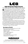
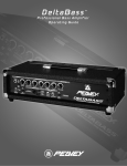
REAR PANEL
2
1
3
(1) FUSE
The unit is AC power line fuse protected from overloads and fault conditions with an ABC-type fast-blow 5
Amp fuse. This fuse is located within the cap of the fuse holder. If the fuse fails, THE FUSE MUST BE
REPLACED WITH THE SAME TYPE AND VALUE IN ORDER TO AVOID DAMAGE TO THE EQUIPMENT AND TO
PREVENT VOIDING THE WARRANTY. If the unit repeatedly blows fuses, it should be taken to a qualified
service center for repair.
(2) IEC POWER CORD CONNECTION
This receptacle is for the IEC line cord (supplied) that provides AC power to the unit.
Never break off the ground pin on any equipment. It is provided for your safety. If the outlet
used does not have a ground pin, a suitable grounding adapter should be used and the third
wire should be grounded properly. To prevent the risk of shock or fire hazard, always be sure
that the mixer and all other associated equipment are properly grounded.
(3) ON-OFF SWITCH
This rocker switch supplies AC power to the PR 15P when switched to the ON position
5
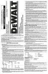
FRONT PANEL
5
6
7
4
8
9
(4) POWER/CLIP LED
Illuminates GREEN when the electronics receive power (when the Power switch (3) is On). Illuminates RED
when amplifier clipping is occurring or the unit has tripped the thermal protection system.
(5) PRIMARY INPUT (CHANNEL 1)
The primary input is switchable between line-level and mic-level input. The line-level input is of the
medium impedance balanced type, and when switched to mic-level it is of a typical low-Z mic input
impedance. Jack (5) is a combo female XLR and 1/4" TRS connector.
(6) PAD
Switches the sensitivity of Channel 1 from line-level to mic-level sensitivity. Pushed all the way in, the
sensitivity is set for line-level input signals, and when the white tab is closer to the front panel, the
sensitivity is increased by 30 dB so it is suitable for mic-level signals.
(7) VOLUME
Controls the gain (level) of the Primary Input (5), Channel 1, of the powered speaker system. It is used to
directly set the system output level for the Channel 1 input signal.
(8) SECONDARY INPUTS, CHANNEL 2 & 3
These consist of 1/4" unbalanced phone jacks for line-level signals, with medium input impedance.
(9) CONCENTRIC VOLUME, CHANNEL 2 & 3
Controls the gain (level) of Channel 2 & 3 inputs. Can be used in conjunction with the Channel 1 volume
control (7) to mix three line-level signals together, or two line-level signals and one mic-level signal.
6
OPERATING INSTRUCTIONS
CAUTIONS
The unit must be disconnected from the AC power source before any work is done on it. Refer all servicing
to qualified service personnel.
The heat sink on the back plate can become hot to the touch. Do not block or cover the heat sink from
ventilation.
Be sure to keep the microphone away from the front of the speaker after switching the mic sensitivity pad
to the OUT position and while setting the microphone level or very loud feedback will occur! Damage to
the system is likely if this occurs!
DO NOT connect the inputs of the PR™15P to the output of a power amplifier. The inputs are meant to be
driven from a line-level strength signal.
DO NOT remove the protective metal grille.
Warning: The PR 15P is very efficient and powerful! This sound system can permanently damage hearing!
Use extreme care setting the overall maximum loudness!
The apparent sound level of the PR 15P can be deceiving due to its clear, clean sound output. The lack of
distortion or obvious distress can make the sound level seem much lower than it actually is. This system is
capable of SPL in excess of 120 dB at 1 M from the speaker!
Flying the PR 15P
Caution: The suspending or flying of the Peavey PR 15P must be done by a certified structural engineer.
Important Safety Information for Mounting the Peavey PR 15P speaker system
Caution: Before attempting to suspend this model of speaker, consult a certified structural engineer.
Speaker can fall due to improper suspension, resulting in serious injury and property damage. Other
enclosures must not be suspended below one, nor should additional weight be suspended from one of
these units. Use only the correct mating hardware. All associated rigging is the responsibility of others.
Always use all four inserts of a given group as a set, NEVER use just one insert to fly a cabinet! The four
insert groupings are a top group of four and a bottom group of four. Some models also have a group of
four on the rear plane of the cabinet.
Maximum enclosure angle from vertical hang: 30˚
Always use a suitable safety chain or wire rope, looped through the top handle, and firmly attached to a
suitable structural member as indicated by a certified structural engineer.
The recommended range of torque for the mounting bolt is 3 to 3-1/2 lb./feet of torque. DO NOT
OVERTIGHTEN! If an insert spins, it has been damaged and the cabinet cannot be flown!
Never transport the cabinet while mounted on an array bracket, or other mounting bracket, as this may
unduly stress the mounting inserts.
WARNING! (note to structural engineer)
For the PR 15P, the thread insertion depth of the end of the mounting bolt should not be more than 1/2"
past the surface of the cabinet.
The correct mounting bolt diameter and threads per inch are: 1/4" X 20. Use of a grade five-bolt is
recommended.
7
G e t t i n g A C P o w e r T o T h e P R ™ 15P
The PR™15P comes with an 8-foot IEC connection AC power cord. If you are using an extension cord or power
strip with this powered speaker, make sure it is of good quality and of a sufficient current capacity to maintain
safety and maximize the power output capability of the PR 15P. Do not connect any other device to the same
extension cord that the PR 15P is connected to.
Special Note for Permanent Installation
When installing the PR 15P, AC power runs will be used and a certified electrician should be consulted to
be sure that all AC wiring complies with local codes and regulations. It is also advisable to use a cable clip
properly affixed to the cabinet to strain relief the IEC power cord connected to the amplifier module at (2)
so the power cord cannot be pulled out or vibrate loose.
Use of PR 15P with a Subwoofer
The built-in pole adapter allows use with the Peavey SP Subcompact 18X and the accessory pole that it is
designed to use, Peavey part #00326540.
The pole used is 36-3/16" long and has a nominal diameter of 1-3/8".
Getting a Signal to the PR 15P
There are a variety of ways to input a signal to the PR 15P.
The primary input (5) provides either a balanced mic- or line-level input, allowing the use of a 1/4" phone
plug, either a standard single-ended (tip-sleeve) plug or a balanced TRS (tip-ring-sleeve) type plug OR a
male XLR plug. Then there are two line-level unbalanced 1/4" phone jacks that can be mixed in with the
primary input.
Do not connect cables to the jacks while the unit is ON and the Volume is turned up!
While a standard single-ended 1/4" phone plug-equipped cable will work well and the balanced input
circuitry of the primary input (5) will provide some interference rejection, a balanced cable using either
the balanced TRS 1/4" phone plug or the XLR plug will provide superior interference rejection and
performance. Sometimes, with difficult interference problems, it will be helpful to lift the shield ground on
a balanced cable at the PR 15P end only. Check any input changes carefully, always turning the volume
control down before plugging and unplugging cables.
Use of high quality, premium cables is recommended for the PR 15P, as these usually have better
shielding and materials and will provide greater long-term reliability. It is usually a good idea to leave
some slack at the input to the PR 15P and also to tape the cables down or run them under a cable guard to
avoid anyone tripping over them or pulling the PR 15P over when stand mounted.
Volume Control Adjustment
The PR 15P is equipped with a volume control to facilitate use in many different applications. With the
volume control adjusted fully clockwise, gain is at maximum and the input sensitivity is 0.375 V RMS for
full-rated output. When driving the PR 15P from a mixer, it may be advantageous to reduce the input
sensitivity by turning the volume control to the halfway point. The PR 15P will now more closely match a
typical power amp.
If the mixing board indicates clipping of its output signals, then all of the PR 15P power capability is not
being utilized cleanly. Clipping the signal before it gets to the PR 15P is not optimal. In that case, reduce
the mixer output level and turn up the volume control on the PR 15P.
The amplifiers in the PR 15P are equipped with DDT™ and an LED indicator to show that DDT™ has
engaged. If the sound seems heavily compressed, check this indicator; and if it is blinking RED more than
occasionally, then the drive level from the mixer (or the volume control on the PR 15P) needs to be
reduced.
8
When first turning on the sound system, switch on all upstream electronics first, then the PR™15P with its
volume control fully counterclockwise (all the way down). Begin checking levels with the mixer output
level controls all the way down, and bring them up slowly with the PR 15P volume control set to the
desired setting (halfway up recommended to start).
Mic/Line Pad Adjustment
The mic/line pad (6) provides for the increased gain needed for microphone use into the primary input (5).
Use a straightened paperclip or small screwdriver to reach through the hole in the rear panel where the
recessed tab is to set its position. Set the Mic/Line Pad to “in,” or the white tab furthest from the panel,
for line-level signal use, and set it “out,” or closest to the panel, for mic-level use. The unit is shipped with
the tab in the line-level position. It is recessed behind the panel so that the gain can not be inadvertently
increased during transport or set-up.
Due to the 30 dB of extra gain that this switch provides, DO NOT leave it in the “out” position for line level
use! This will result in input-stage clipping of the PR 15P and cause unnecessary distortion.
Mixing Signals Using the Volume Knobs
The gain of all three channels can be adjusted independently from the other channels via the volume
knobs (7) and (9). Channel 1 can be used for either line-level signals or as a mic input, and mixed with two
other line-level signals.
The PR 15P has plenty of gain, so do not overload the speaker system preamp inputs by driving them with
a signal that is too hot. Full output mixer levels well in excess of 0 dB will not going to be necessary to
drive the unit to full power capacity.
TROUBLESHOOTING
No Output at All
First, make sure the unit has AC power and is turned ON. Make sure the Power/Clip LED (4) is illuminated
Green. If not, make certain the ON/OFF switch (3) is in the ON position and check the IEC power cord
connection (2) by ensuring it is fully engaged and seated. Make certain the AC line cord is plugged into a
working AC outlet. Finally, check the fuse (1). (See the Rear Panel: Fuse section, for safety instructions.)
Once assured your unit is getting AC power, check that the PR 15P is getting a signal. Temporarily disconnect
the cable running to its inputs and connect it to some other device capable of reproducing the signal (i.e., a
power amp and speaker). If this produces a signal, make sure that all Volume controls being used have been
turned up to a satisfactory level (one-third to halfway).
If the PR 15P has been subjected to direct sunlight or excessive heat, the built-in thermal protection may have
been triggered. The power/clip LED will be illuminated RED if this is the case. If so, turn off the PR 15P and let it
cool for a sufficient amount of time.
If there is still no output, contact your authorized Peavey dealer or the Peavey International Service Center.
9
Hum or Buzz
If the PR™15P is producing a hum or buzz, this can be AC outlet related. Try plugging the PR 15P into a
different AC outlet. Sometimes, if a different circuit (breaker) is used for the mixer and the PR 15P, it can
cause hum problems.
Ensure that shielded cables have been used to route the signal to the PR 15Ps inputs. If speaker cables
with 1/4" plugs are used as an input cables instead of shielded cables, it will be prone to hum or buzz.
Hum may be ground loop related. Try lifting the ground connection at the speaker end of the signal cable if
it is a balanced signal cable. Check any input changes carefully by first turning down the volume control,
plugging and unplugging cables, or lifting the shield ground at the speaker end.
Check to make sure light dimmers are not on the same circuit as the PR 15P, the mixer or any source
devices. If light dimmers are used, then it may be necessary to turn them full ON or full OFF to eliminate or
reduce hum. This is a typical AC wiring/light dimmer interference problem, and not a design flaw of the PR
15P. The third wire (ground plug) on the AC plug should NEVER be removed or broken off.
Distorted or Fuzzy Sound
First, ensure the mixer (signal source) is not clipping or being overdriven. Make sure the volume control/s
(7) and (9) on the PR 15P have not been set too low.
Check that the input plugs are fully seated in the input jacks (5) and (8) on the rear panel of the PR 15P.
Ensure that the proper MIC/LINE PAD setting is being used (6) for line-level signals, or that a power amp
has not been plugged into one of the input jacks of the PR 15P.
If an extension cord is being used to provide the AC power to the unit, ensure that it is of sufficient
current capacity and that it is not also being used to supply power to any other device.
The PR 15P has built-in EQ to extend and smooth the natural response of the speakers in the system.
Bass boost and HF EQ have been applied and the system has a nominally flat response, so it should
require little, if any, additional EQ. If excessive additional bass boost or HF boost have been added
externally to the PR15P, it could cause premature overload at high SPL. Reduce the amount of any external
(mixer, rack) EQ and see if that clears up the distortion.
Finally, realize that even though the PR 15P is a powerful and high output unit, it does ultimately have
limits, and it may need additional powered units (or a subwoofer) to provide enough sound output or
coverage. In this case, try turning the mixer levels down a little to see if that clears things up.
If, after checking all the things listed to check and anything else you can think of to check safely, and the
system still exhibits problems, carefully note all conditions and check with your Peavey dealer for advice.
Care and Maintenance
Your PR 15P is a sturdy and durable product and will provide years of reliable use if properly cared for.
Use common sense and read the safety warnings to avoid hazardous operating conditions.
The unit must be disconnected from the AC power source before any work is done on it. Refer all servicing
to qualified service personnel.
Sunlight/Heat
Avoid prolonged exposure to direct sunlight, as this may cause the unit to overheat and thermally shut
off. Excessively hot operating conditions can also cause a thermal shutdown.
Do not store in extremely hot or cold conditions or extremely high humidity. Always allow unit to come to
room temperature before use.
Cleaning
Never clean the PR 15P while plugged in or turned ON! When the unit has been fully disconnected from AC
power sources, use a dry cloth to remove soil or other dirt. Never use strong solvents on the PR 15P, as
they could dameage the cabinet. Do not allow ANY fluids to drip inside the PR 15P.
10
Touchup
For an overall finish enhancement and protective coating, use gloves to apply a plastic finish protector,
such as Armor-All® protectant, to the surface of the plastic cabinet only. Note that the cabinet will be
slippery after these treatments; rub them down vigorously with a dry, lint-free cloth to minimize this.
Check for Secure Hardware
After the first few months of use and periodically thereafter, check the hardware of the PR 15P for
tightness, including the rear panel screws and the screws that hold the baffle and rear cabinet together.
The unit is subject to a great deal of vibration, and this could cause them to loosen with use.
Architectural and Engineering Specifications
The powered loudspeaker system shall have a frequency response from 47 Hz to 20 kHz. The peak SPL
with inaudible distortion shall reach 120 dB with music as a source, when measured at a distance of 1M
and driven to full output capacity. The system shall utilize a 15" heavy duty woofer and an RX™14
compression driver tweeter. The nominal radiation pattern shall be 90˚ in the horizontal plane, and 40˚ in
the vertical plane.
The powered, bi-amplified loudspeaker system shall have a group of medium impedance input connectors
consisting of one combo female XLR and 1/4" TRS phone jack, and two 1/4" phone jacks, on the rear
panel. A volume control will be located near each input jack. The combo female XLR and 1/4" TRS phone
jack will have a gain adjust pad that provides for switching between line-level input signals, and mic-level
input signals.
The system power amplifiers shall have an unfiltered frequency response of 10 Hz to 30 kHz which
deviates no more than +0, -1 dB up to rated power, a damping factor greater than 100 @ 1 kHz into
8 Ohms, hum and noise better than 90 dB below rated power, and THD and IMD of less than 0.1%. The
woofer amplifier shall be capable of 150 W into a 8 Ohm nominal load, and the tweeter amplifier shall be
capable of 50 W output into a 8 Ohm load, and both shall incorporate independent DDT™ compression.
The input signal shall be electronically divided into high frequencies and low frequencies by a staggeredpole, third order slope line-level crossover at 2 kHz. The low frequencies shall be processed to provide
bass boost, subsonic filtering and overall response shaping, and the high frequencies shall be equalized
for constant directivity horn EQ- and response-shaping.
The enclosure shall be constructed of injection-molded polypropylene of 1/4" nominal thickness with a UL
flame rating, and reinforcing ribs internally. A handgrip shall be molded-in on the top rear edge, and one
on each side of the woofer.
A powder-coated metal grille shall be provided for woofer protection. The cabinet shall incorporate a pole
mount for speaker stand use, four tall sturdy rubber feet for floor standing use, and four mounting point
inserts on the top and bottom each for flying use.
The outside dimensions shall be: 28.56" tall by x 21.31" wide (11.50" in rear) by x 17.00" deep, and the
weight shall be 52 lbs. Power requirements shall be: 100 Watts nominal, 120 VAC, 60 Hz domestic and
240 VAC, 50 Hz (European). The loudspeaker system shall be called a Peavey PR 15P.
11
Peavey PR™15P
SPECIFICATIONS
Enclosure: Peavey PR 15P (domestic)
Frequency Response:
47 Hz to 20 kHz
Low Frequency Limit (-3 dB point):
47 Hz
Useable Low Frequency Limit (-10 dB
point):
36 Hz
Internal Power Amplifiers (@120 VAC
line):
Woofer - 200 Watts peak dynamic
power
150 Watts @ less than 0.1% distortion
Tweeter - 70 Watts peak dynamic
power
50 Watts @ less than 0.1% distortion.
Nominal Sensitivity (1W @1M, swept
sine input in anechoic environment):
97 dB
Maximum Sound Pressure Level:
120 dB music peak
Nominal Radiation Angles:
90˚ horizontal by 40˚ vertical
Transducer Complement:
12" heavy duty woofer, and RX™14 1.4"
titanium diaphragm compression driver
tweeter
Box Tuning Frequency (Fbox):
55 Hz
Electroacoustic Crossover Frequency:
2000 Hz
Crossover Type:
Internal Electronic two-way crossover
with CD horn EQ, level matching, bass
boost and subsonic filtering.
Crossover Slopes:
18 dB/octave (third order) low pass,
18 dB/octave (third order) high pass,
both with staggered poles and driver
EQ. Unit has horn spatially aligned with
woofer, so there is no need for phase
alignment or time delay of the signals.
Electronic Input Impedance (Nominal):
10 k Ohms unbalanced, 20 k Ohms
balanced line level, 2.4 k Ohms
balanced mic level.
Input Connections:
One combo female XLR/ 1/4" phone
jack providing balanced operation, with
switch selectable mic or line level
sensitivity. Also has two 1/4" phone
jack line level unbalanced inputs with a
concentric pair of level controls.
Enclosure Materials and Finish:
Injection-molded polypropylene of a
nominal thickness of 1/4" with internal
ribbing and bracing, and with textured
finish. Molded material is dark gray.
Mounting:
Subwoofer pole-mounting via moldedin mount, flying via Versamount™ 70
and four rubber feet for floor use.
Dimensions:
28.56" (72.5 cm) tall by 21.31"
(54.1 cm) wide {11.50"/29.2 cm in rear}
by 17.00" (43.2 cm ) deep
Optional Accessories:
Impulse® 200 Floor Monitor Kit
(FG# 00370480)
Net Weight:
52 lbs.
12
Additional Remarks:
Also available as a passively crossedover unit, the Peavey PR 15
ELECTRONICS AND AMPLIFIER
SPECIFICATIONS:
Electronic Input Impedance (Nominal):
Primary balanced input: 20 k ohms line
level sensitivity selected, 2.4 k ohms
mic level sensitivity selected, 10 k ohms
unbalanced 1/4".
Mic Switch Sensitivity Increase:
30 dB
Infrasonic filter protection:
36 dB/octave roll-off
Nominal Amplifier Frequency Response:
+0, -1 dB from 10 Hz to 30 kHz
Hum and Noise:
Greater than 90 dB below rated power
DDT Dynamic Range:
Greater than 14 dB
THD and IM:
Typically less than 0.1 %
Damping Factor:
Greater than 100 @ 1000 Hz, 8 Ohms
Power requirements of Peavey PR™12P
System (domestic):
Nominal 100 Watts, 120 VAC, 60 Hz
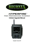
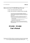
FREQUENCY RESPONSE CURVES
Amplitude Response (1m On-Axis)
dB SPL (re 20 Pa)
110
100
90
80
70
60
20
Figure 1
50
100
200
500
1k
Frequency (Hz)
13
2k
5k
10k
20k
Notes:
14
PEAVEY ELECTRONICS CORPORATION LIMITED WARRANTY
Effective Date: July 1, 1998
What This Warranty Covers
Your Peavey Warranty covers defects in material and workmanship in Peavey products purchased and serviced in the U.S.A. and Canada.
What This Warranty Does Not Cover
The Warranty does not cover: (1) damage caused by accident, misuse, abuse, improper installation or operation, rental, product modification or neglect; (2) damage occurring during shipment; (3) damage caused by repair or service performed by persons not authorized by Peavey; (4) products on which the serial number
has been altered, defaced or removed; (5) products not purchased from an Authorized Peavey Dealer.
Who This Warranty Protects
This Warranty protects only the original retail purchaser of the product.
How Long This Warranty Lasts
The Warranty begins on the date of purchase by the original retail purchaser. The duration of the Warranty is as follows:
Product Category
Duration
Guitars/Basses, Amplifiers, Pre-Amplifiers, Mixers, Electronic
Crossovers and Equalizers
2 years *(+ 3 years)
Drums
2 years *(+ 1 year)
Enclosures
3 years *(+ 2 years)
Digital Effect Devices and Keyboard and MIDI Controllers
1 year *(+ 1 year)
Microphones
2 years
Speaker Components (incl. speakers, baskets, drivers,
diaphragm replacement kits and passive crossovers)
and all Accessories
1 year
Tubes and Meters
90 days
[*Denotes additional warranty period applicable if optional Warranty Registration Card is completed and returned to Peavey by original retail purchaser within 90 days of purchase.]
What Peavey Will Do
We will repair or replace (at Peavey's discretion) products covered by warranty at no charge for labor or materials. If the product or component must be shipped to
Peavey for warranty service, the consumer must pay initial shipping charges. If the repairs are covered by warranty, Peavey will pay the return shipping charges.
How To Get Warranty Service
(1) Take the defective item and your sales receipt or other proof of date of purchase to your Authorized Peavey Dealer or Authorized Peavey Service Center.
OR
(2) Ship the defective item, prepaid, to Peavey Electronics Corporation, International Service Center, 412 Highway 11 & 80 East, Meridian, MS 39301 or Peavey
Canada Ltd., 95 Shields Court, Markham, Ontario, Canada L3R 9T5. Include a detailed description of the problem, together with a copy of your sales receipt or
other proof of date of purchase as evidence of warranty coverage. Also provide a complete return address.
Limitation of Implied Warranties
ANY IMPLIED WARRANTIES, INCLUDING WARRANTIES OF MERCHANTABILITY AND FITNESS FOR A PARTICULAR PURPOSE, ARE LIMITED IN DURATION TO THE
LENGTH OF THIS WARRANTY.
Some states do not allow limitations on how long an implied warranty lasts, so the above limitation may not apply to you.
Exclusions of Damages
PEAVEY'S LIABILITY FOR ANY DEFECTIVE PRODUCT IS LIMITED TO THE REPAIR OR REPLACEMENT OF THE PRODUCT, AT PEAVEY'S OPTION. IF WE ELECT TO
REPLACE THE PRODUCT, THE REPLACEMENT MAY BE A RECONDITIONED UNIT. PEAVEY SHALL NOT BE LIABLE FOR DAMAGES BASED ON INCONVENIENCE, LOSS OF
USE, LOST PROFITS, LOST SAVINGS, DAMAGE TO ANY OTHER EQUIPMENT OR OTHER ITEMS AT THE SITE OF USE, OR ANY OTHER DAMAGES WHETHER INCIDENTAL,
CONSEQUENTIAL OR OTHERWISE, EVEN IF PEAVEY HAS BEEN ADVISED OF THE POSSIBILITY OF SUCH DAMAGES.
Some states do not allow the exclusion or limitation of incidental or consequential damages, so the above limitation or exclusion may not apply to you.
This Warranty gives you specific legal rights, and you may also have other rights which vary from state to state.
If you have any questions about this warranty or service received or if you need assistance in locating an Authorized Service Center, please contact the Peavey
International Service Center at (601) 483-5365 / Peavey Canada Ltd. at (905) 475-2578.
Features and specifications subject to change without notice.
15
Features and specifications subject to change without notice.
Peavey Electronics Corporation • 711 A Street • Meridian • MS • 39301
(601) 483-5365 • FAX (601) 486-1278 • www.peavey.com
©2003
80304968
Printed in the U.S.A. 10/03