1
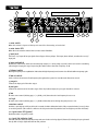
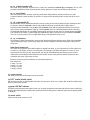
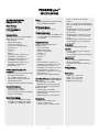
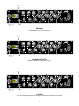
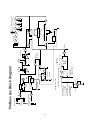
PROBASS 500 Operation Manual
For more information on other great Peavey products, go to your local Peavey dealer or online at www.peavey.com
Intended to alert the user to the presence of uninsulated “dangerous voltage” within the product’s
enclosure that may be of sufficient magnitude to constitute a risk of electric shock to persons.
Intended to alert the user of the presence of important operating and maintenance (servicing)
instructions in the literature accompanying the product.
CAUTION: Risk of electrical shock — DO NOT OPEN!
CAUTION: To reduce the risk of electric shock, do not remove cover. No user serviceable parts inside.
Refer servicing to qualified service personnel.
WARNING: To prevent electrical shock or fire hazard, do not expose this appliance to rain or moisture.
Before using this appliance, read the operating guide for further warnings.
Este símbolo tiene el propósito, de alertar al usuario de la presencia de “(voltaje) peligroso” sin
aislamiento dentro de la caja del producto y que puede tener una magnitud suficiente como para
constituir riesgo de descarga eléctrica.
Este símbolo tiene el propósito de alertar al usario de la presencia de instruccones importantes sobre la
operación y mantenimiento en la información que viene con el producto.
PRECAUCION: Riesgo de descarga eléctrica ¡NO ABRIR!
PRECAUCION: Para disminuír el riesgo de descarga eléctrica, no abra la cubierta. No hay piezas útiles
dentro. Deje todo mantenimiento en manos del personal técnico cualificado.
ADVERTENCIA: Para evitar descargas eléctricas o peligro de incendio, no deje expuesto a la lluvia o
humedad este aparato Antes de usar este aparato, Iea más advertencias en la guía de operación.
Ce symbole est utilisé dans ce manuel pour indiquer à l’utilisateur la présence d’une tension dangereuse
pouvant être d’amplitude suffisante pour constituer un risque de choc électrique.
Ce symbole est utilisé dans ce manuel pour indiquer à l’utilisateur qu’il ou qu’elle trouvera d’importantes
instructions concernant l’utilisation et l’entretien de l’appareil dans le paragraphe signalé.
ATTENTION: Risques de choc électrique — NE PAS OUVRIR!
ATTENTION: Afin de réduire le risque de choc électrique, ne pas enlever le couvercle. Il ne se trouve à
l’intérieur aucune pièce pouvant être reparée par l’utilisateur. Confiez I’entretien et la réparation de
l’appareil à un réparateur Peavey agréé.
AVERTISSEMENT: Afin de prévenir les risques de décharge électrique ou de feu, n’exposez pas cet
appareil à la pluie ou à l’humidité. Avant d’utiliser cet appareil, lisez attentivement les avertissements
supplémentaires de ce manuel.
Dieses Symbol soll den Anwender vor unisolierten gefährlichen Spannungen innerhalb des Gehäuses
warnen, die von Ausreichender Stärke sind, um einen elektrischen Schlag verursachen zu können.
Dieses Symbol soll den Benutzer auf wichtige Instruktionen in der Bedienungsanleitung aufmerksam
machen, die Handhabung und Wartung des Produkts betreffen.
VORSICHT: Risiko — Elektrischer Schlag! Nicht öffnen!
VORSICHT: Um das Risiko eines elektrischen Schlages zu vermeiden, nicht die Abdeckung enfernen. Es
befinden sich keine Teile darin, die vom Anwender repariert werden könnten. Reparaturen nur von
qualifiziertem Fachpersonal durchführen lassen.
ACHTUNG: Um einen elektrischen Schlag oder Feuergefahr zu vermeiden, sollte dieses Gerät nicht dem
Regen oder Feuchtigkeit ausgesetzt werden. Vor Inbetriebnahme unbedingt die Bedienungsanleitung lesen.
2
IMPORTANT SAFETY INSTRUCTIONS
WARNING: When using electrical products, basic cautions should always be followed, including the following:
1.
2.
3.
4.
5.
6.
7.
8.
9.
10.
11.
12.
13.
14.
15.
16.
17.
Read these instructions.
Keep these instructions.
Heed all warnings.
Follow all instructions.
Do not use this apparatus near water.
Clean only with a dry cloth.
Do not block any of the ventilation openings. Install in accordance with manufacturer’s instructions.
Do not install near any heat sources such as radiators, heat registers, stoves or other apparatus (including
amplifiers) that produce heat.
Do not defeat the safety purpose of the polarized or grounding-type plug. A polarized plug has two blades with one
wider than the other. A grounding type plug has two blades and a third grounding plug. The wide blade or third
prong is provided for your safety. If the provided plug does not fit into your outlet, consult an electrician for
replacement of the obsolete outlet.
Protect the power cord from being walked on or pinched, particularly at plugs, convenience receptacles, and the
point they exit from the apparatus.
Only use attachments/accessories provided by the manufacturer.
Use only with a cart, stand, tripod, bracket, or table specified by the manufacturer, or sold with the apparatus. When
a cart is used, use caution when moving the cart/apparatus combination to avoid injury from tip-over.
Unplug this apparatus during lightning storms or when unused for long periods of time.
Refer all servicing to qualified service personnel. Servicing is required when the apparatus has been damaged in
any way, such as power-supply cord or plug is damaged, liquid has been spilled or objects have fallen into the
apparatus, the apparatus has been exposed to rain or moisture, does not operate normally, or has been dropped.
Never break off the ground pin. Write for our free booklet “Shock Hazard and Grounding.” Connect only to a power
supply of the type marked on the unit adjacent to the power supply cord.
If this product is to be mounted in an equipment rack, rear support should be provided.
Exposure to extremely high noise levels may cause a permanent hearing loss. Individuals vary considerably in
susceptibility to noise-induced hearing loss, but nearly everyone will lose some hearing if exposed to sufficiently
intense noise for a sufficient time. The U.S. Government’s Occupational and Health Administration (OSHA) has
specified the following permissible noise level exposures:
Duration Per Day In Hours
8
6
4
3
2
1 1/2
1
/2
1/4 or less
Sound Level dBA, Slow Response
90
92
95
97
100
102
105
110
115
According to OSHA, any exposure in excess of the above permissible limits could result in some hearing loss. Ear plugs or protectors to the
ear canals or over the ears must be worn when operating this amplification system in order to prevent a permanent hearing loss, if exposure
is in excess of the limits as set forth above. To ensure against potentially dangerous exposure to high sound pressure levels, it is
recommended that all persons exposed to equipment capable of producing high sound pressure levels such as this amplification system be
protected by hearing protectors while this unit is in operation.
SAVE THESE INSTRUCTIONS!
3
ENGLISH
PROBASS 500™
Congratulations on your purchase of the PROBASS 500 by Peavey. You’ll find features and tone galore in this 2-rack space bass
amplifier. The PROBASS 500 offers a tube front-end (preamp) section for that smooth tube sound combined with a solid-state
amplifier for mind-blowing power. The PROBASS 500 is a professional bass amp with flexible features not even found on the
high-end boutique power amps. This amp includes a -10 dB pad switch for your active basses; a tuner send with an input mute
for silent tuning; both active EQ and full parametric EQ; front and rear 1/4" inputs; a 3-position ground lift switch for those
troublesome situations; a side chain effects loop with wet/dry control and much more. Combine these features with Peavey’s
long-standing reputation for reliability and you can’t go wrong!
Please read this guide carefully to ensure your personal safety as well as the safety of your equipment.
Features
◆
12AX7 preamp tube for warm tube sound
◆
500 Watts @ 2 Ohms; 350 Watts @ 4 Ohms; 200 Watts @ 8 Ohms
◆
front and rear 1/4" input jacks
◆
-10 dB pad for active basses
◆
tuner send jack for easy tuner hookup
◆
input mute with blinking LED for silent tuning
◆
contour control for tube-type EQ curve
◆
active low and high shelving-type EQ
◆
3-bands of versatile‚ full-parametric equalization
◆
side chain effects loop with wet/dry control
◆
foot switch capable input mute and effects loop
◆
low Z electronically balanced line out with pre/post EQ switch
◆
ground lift switch for line out
◆
both Speakon® and 1/4" speaker jacks
◆
preamp out/power amp in jacks
◆
DDT speaker protection system with defeat switch
◆
2-rack space unit
4
Front Panel
1
5
7
9
10
14
2
15
3
16
4
6
8
12
25
14–22 full parametric EQ
17
18
19
20
21
22
14–22 full parametric EQ
11
23
24
26
13
1 mute switch
When this switch is depressed the input is muted for silent tuning or break time!
2 mute status LED
When the mute switch is enabled the red mute status LED blinks.
3 input jack
This mono 1/4" input will accept signals from all types of bass pickups. This input‚ when utilized‚ overrides the rear 1/4"
input jack.
4 input pad switch
Provided for instruments that have extremely high output (i.e. active pickup systems)‚ which can result in overdriving
(distorting) the input gain stage. Depressing the switch reduces the level of input by 10 dB.
5 hi boost switch
Adds high frequency boost equalization. Notice that the high frequency boost becomes less effective with more preamp gain.
6 low cut switch
Used to reduce the amount of low frequency throughout the system for smoother tube distortion sounds.
7 pre gain
Controls the input gain of the tube stages.
8 post gain
Controls the volume level of the tube stages. If the clip indicator lights‚ the post gain should be reduced.
9 low
An active tone control (shelving type‚ +/-15 dB @ 30 Hz) that varies the low frequency boost or cut.
10 high
An active tone control (shelving type‚ +/-15 dB @ 10 kHz) that varies the high frequency boost or cut.
11contour control
Provides a specially voiced EQ as the knob is rotated clockwise. When the knob is fully counterclockwise (set to 0)‚ there
is no voicing added. (This control is similar to the old passive tube EQs with the lows and highs up and the mid down.)
12 signal status LED (green)
Illuminates when a signal is present.
13 signal clip indicator (red)
This LED indicates (when lit) that the preamp and tone circuits are being clipped (distorted). Reducing the post gain until
the clip LED no longer lights will alleviate this problem.
5
14–22 3-band parametric EQ
Each band of the parametric EQ section has a control for: cut/boost; bandwidth (Q) and frequency. This is a full
parametric EQ! All three bands of parametric EQ overlap‚ giving you control over the entire tonal spectrum.
14‚ 17‚ 20 cut/boost
This control behaves like any other active EQ control where CW (clockwise) rotation provides boost‚ CCW
(counterclockwise) rotation provides cut and the 12 o’clock position (detent) provides no action at all (no cut or
boost).
15‚ 18‚ 21 bandwidth (Q)
The bandwidth controls determine how wide or narrow a range of tones will be affected by the cut/boost control.
For instance‚ when the bandwidth control is fully CCW‚ the cut/boost control will affect a wide range of
frequencies (wide bandwidth = low Q). When the bandwidth is fully CW‚ the cut/boost will affect a very narrow
range of tones (narrow bandwidth = high Q). If the bandwidth control is somewhere between the two extremes‚
the bandwidth will likewise be somewhere between wide and narrow. As the control is rotated CW‚ the bandwidth
gets narrow. As the control is rotated CCW‚ the bandwidth gets wide. A good place to start is with the bandwidth
set to the 3 o’clock position. This is roughly where many “semi-parametric” EQs are set.
16‚ 19‚ 22 frequency
The frequency controls determine the center point at which the cut/boost will take action. Think of the bandwidth
control affecting the range of tones being acted upon and the frequency control determining the center point of
those tones.
Note about frequencies:
The electric bass generates notes with frequencies ranging from about 30.9 Hz (low B-string on a five-string bass)
to about 523.3 Hz (high C-string on a six-string bass). It may help you to think of frequencies as notes on your
instrument or notes that you sing. By doing this‚ the concept of bandwidth and frequency becomes easier to
understand. The bandwidth control determines the number of notes being affected and the frequency control
determines the center of that range of notes.
Below are a few more pitches with their corresponding frequencies:
Four-string bass:
E string = 41.2 Hz
A string = 55.0 Hz
D string = 73.4 Hz
G string = 98.0 Hz
23 master volume
This knob controls the overall volume level of the system.
24 DDT™ enable/disable switch
DDT speaker protection is disabled when the button is depressed or in the “in” position. DDT should be enabled at all
times to protect your speakers.
25 power LED/DDT indicator
The LED is green when the power switch is in the “on” position. During normal operation‚ this LED also acts as a DDT/clip
indicator. The LED illuminates red when DDT speaker protection is taking place or when the power amp is clipping (if DDT
is disabled).
26 power switch
Used to turn AC mains power on or off.
6
Rear Panel
30
31
32
33
34
35
36
37
38
39
40
41
42
27
28
29
27 ground polarity switch
The ground switch is a 3-position‚ rocker-type switch. Under normal operation it should be in the center (zero)
position. If hum or noise is present with the ground switch in the center position‚ place the ground polarity
switch to positive or negative (+ or -) to minimize hum. Should a problem continue‚ consult your authorized
Peavey dealer‚ the Peavey factory or a qualified service technician. Note: The ground switch is not functional on
220/240 Volt models.
28 reset/circuit breaker switch
Use this switch to restore power to the unit when the internal breaker is tripped. Turn the power switch to the
off position before resetting the breaker. To reset‚ push the reset button in and release it. Turn the unit back on
and confirm that the power LED is on. If the breaker is tripped again upon power-up‚ consult your authorized
Peavey dealer‚ the Peavey factory or a qualified service technician.
29 IEC connector/detachable line cord
For your safety‚ we have incorporated a detachable‚ 3-wire line (mains) cord with proper grounding facilities. It
is not advisable to remove the ground pin under any circumstances. If it is necessary to use the amp without
proper grounding facilities‚ a suitable grounding adapter should be used. Refer to the back of your amp for the
proper voltage requirements before connecting to a power receptacle.
30 speaker output jacks
There are two 1/4" jacks and one Neutrik type jack that provide the powered signal from the amplifier. Each
connector is electrically the same (parallel). Use one of the jacks to connect your speaker cabinet and the other
to add a second speaker cabinet in parallel. The minimum speaker load impedance is 2 Ohms or two 4 Ohm
speakers in parallel.
Warning: To prevent the amplifier from overheating‚ the front and rear fan vents should remain clear of
obstructions.
31 power amp input
Used to connect a line level signal to the power amplifier (i.e. external preamp). This jack‚ when used‚
disconnects the internal preamp.
32 preamp out
The preamp output can be used to route the amplified signal to a mixing console‚ tape recorder or other device.
Connect the preamp output using a shielded cable to an input of one of these devices. This does not affect the
operation of the amplifier. The preamp out and power amp in jacks can also be used as a line level effects patch
point.
33 remote jack switch
Provided for an optional footswitch. Allows remote selection of the input mute and the effects loop. Mute switch
on front panel must be depressed to the IN position for the footswitch to function properly.
34 effects return
Input for returning signals from an external low-level effects device or signal processing unit.
7
35 effects send
Output for supplying signal to an external low-level effects or signal processing unit.
36 effects mix
Since the effects loop on the ProBass 500 is a side-chain effects loop‚ the mix between the dry (unaffected) and wet (effects)
signal can be adjusted with this control. When the control is fully CCW‚ there will be no effects present (dry). When the
control is fully CW‚ the effects loop is fully wet. This same mix is set to the post EQ XLR as well as the main preamp out.
37 line out ground lift switch
Provides ground to be made from the line out jack or lifted to eliminate ground loops from the ProBass 500 and external
source(s). There may be some rooms or situations when audible hum and/or noise is present. Minimizing this noise may
be possible by depressing this switch.
38 select switch
Allows selection of a pre EQ or post EQ send to the low Z balanced line out jack. The “out” position selects pre EQ and
the “in” position selects post EQ line out.
39 line out (low Z balanced)
An XLR jack is provided to route the signal to a mixing console or recording equipment. This output can be selected for
pre EQ or post EQ operation.
40 line out level control
Controls the output level of the balanced line level output.
41 tuner send jack
This 1/4" jack is provided for connecting an instrument tuner to your amp. Its signal is buffered off the input jack so it is
just like plugging directly into the tuner.
42 auxiliary input jack
This 1/4" jack is provided for connecting an instrument to the amp from behind the rack. It is just like plugging directly into
the front panel input jack. Note that the front panel input jack overrides the rear panel input jack. This means that if you are
using the rear panel input jack and then plug another instrument into the front panel‚ the rear panel input will be defeated.
8
PROBASS 500™
SPECIFICATIONS
SYSTEM SPECIFICATIONS
Mains Circuit Breaker:
5 amps
Noise:
Typically greater than 102 dB below full
power @ 8 Ohms unweighted
Mains Voltage:
120 VAC 60 Hz
Power Consumption:
DDT Dynamic Range:
Typically greater than +15 dB
600 Watts
Frequency Response:
Hum and Noise:
Typically greater than -80 dB unweighted.
With controls set as follows:
Pad = passive
Bright = Normal (out)
Low Cut = Normal (out)
Pre Gain = 9 o’clock (roughly 2)
Post Gain = 10
Contour = 0
Low = 0
High = 0
Parametric Band 1: cut/boost = 0;
bandwidth = 0; frequency = 0
Parametric Band 2: cut/boost = 0;
bandwidth = 0; frequency = 0
Parametric Band 3: cut/boost = 0;
bandwidth = 0; frequency = 0
Master Volume = 5
POWER AMPLIFIER SECTION
Protection:
Electronic current limit protection circuit
Thermal protection circuit
D.C. crowbar protection circuit
DDT speaker protection circuit with
defeat switch and LED
Variable speed fan‚ thermally controlled
General Information:
Minimum Load = 2 Ohms
Input sensitivity: 1.0 VRMS
Two 1/4" speaker jacks and one Neutrik
Speakon® all in parallel
Rated Power Output:
500 Watts (31.62 VRMS) into 2 Ohms
350 Watts (37.42 VRMS) into 4 Ohms
200 Watts (40.00 VRMS) into 8 Ohms
+0/-0.61 dB‚ 100mW to 160 w RMS 20 Hz
to 20 kHz (8 Ohm load‚ typically below
0.2% THD+N)
PREAMP SECTION
Settings for measurements unless
otherwise noted:
Pad = passive (out)
Bright = Normal (out)
Low Cut = Normal (out)
Pre Gain = 2
Post Gain = 10
Contour = 0
Low = 0
High = 0
Parametric Band 1: cut/boost = 0;
bandwidth = 0; frequency = 12 o’clock
Parametric Band 2: cut/boost = 0;
bandwidth = 0; frequency = 12 o’clock
Parametric Band 3: cut/boost = 0;
bandwidth = 0; frequency = 12 o’clock
Master Volume = 5
Line Out Level = 10 (fully clockwise)
Input Sensitivity (level to achieve full power):
With Pad out:
Nominal input: 100 mV RMS
Minimum input: 5 mV (pre gain @ 10)
Maximum input: 2.0 V (pre gain @ 1)
With Pad -10 dB in:
Nominal input: 316 mV RMS
Minimum input: 16 mV (pre gain and
master fully CW)
Maximum input: 6.3 V (pre gain @ 1)
Equalization:
Bright Boost: +8 dB @ 5.5 kHz
Low Cut: -3 dB @ 125 Hz
Contour: Set @ 10 provides +4 dB @
9
35 Hz; -30 dB @ 400 Hz; +4 dB @
5.5 kHz
Low: +/-15 dB @ 20 Hz; Shelving type EQ
High: +/-15 dB @ 5 kHz–20 kHz; Shelving
type EQ
Parametric Band 1: cut/boost = +12 dB/
-20 dB; BW (Q) = 0.3–8.5, Frequency =
40 Hz–400 Hz
Parametric Band 2: cut/boost = +12 dB/
-20 dB; BW (Q) = 0.3–8.5, Frequency =
150 Hz
Parametric Band 3: cut/boost = +12 dB/
-20 dB; BW (Q) = 0.3–8.5, Frequency =
800 Hz–8 kHz
Tuner Send:
Instrument level through a buffer
Line Out:
-∞ to fx loop level for post setting (for
nominal input)
-∞ to instrument level for pre setting (for
nominal input)
Effects Loop:
Set for -10 dB (0.315 VRMS) with post
gain @ 5; Master @ 10
Controlled via footswitch‚ ground tip to
defeat
Preamp Output:
1 VRMS nominal
Dimensions:
Width: 19.000" (48.26 cm)
Depth: 12.750" (32.39 cm)
Height: 3.500" (8.89 cm)
Weight: 24.8 lb (11.25 kg)
SUGGESTED SETTINGS
Below are some suggested settings that should give you a starting point in developing your own sound with the ProBass500.
Experiment. Play. The ProBass500 is a versatile amp and with some experimentation‚ you’ll find usable settings for every situation.
Note:
1
Select pad OUT for passive instruments and pad IN for active instruments.
2
Use the pre gain as a volume control. Remember to reduce the post gain if the clip indicator lights.
3
The more pre gain—the more grunge!
4
The master volume should be used to raise or lower the overall volume once the pre gain and tone settings have been set.
5
Always make sure the red clip indicator is not on. If it does start to light up‚ reduce the post gain control.
6
Set the low cut OUT for more grunge in the lows!
Hi-boost OUT
Pad OUT for passive
and IN for active
Low-cut OUT
lay.it.down
A good general setting for just laying down the groove!
Hi-boost IN
Pad OUT for passive
and IN for active
Low-cut OUT
phunk.101
Add just a little funk to your sound with these settings.
10
Hi-boost OUT
Pad OUT for passive
and IN for active
Low-cut OUT
old.timer
Great settings for those classic grooves!
Hi-boost OUT
Pad OUT for passive
and IN for active
Low-cut IN
smash.your.teeth
Working with the dirt—add some grunge!
Hi-boost OUT
Pad OUT for passive
and IN for active
Low-cut OUT
p.phunk
Carve your way through the cosmos and beyond with these phunk-induced settings!
11
12
buffer
buffer
-10 dB
pad
1
2
ground lift
line drivers
3
post EQ
2(+)
1(-)
1(+)
2(-)
status LED
Green = Pwr On
Red = DDT/Clip
Post Gain
Pre/Post
EQ Select
buffer
preamp out
line level
1 VRMS 0 dB
line out level
pre EQ
buffer
Gain
12AX7
high
boost
Preamp
speaker jacks power amp buffer/DDT
power amp in
Speakon
200 Watts RMS
with 8 ohm load
350 Watts RMS
with 4 ohm load
12AX7
low cut
Balanced Line Out
switch
logic
Minimum Load is 2 ohms
Mute LED
Mute Switch
-10 dB Pad
In/Out
500 Watts RMS
with 2 ohm load
Rear Panel Tuner Send
Instrument Level
Front Panel Input
Rear Panel Input
hi-pass
switch
logic
cut/boost
0 db
footswitch
ring
tip
frequency
effects send
1 VRMS
Effects Loop
Effects Loop
Side Chain
Wet/Dry Control
mid
+/- 15 dB
high mid
+/- 15 dB
3-band parametric EQ
low/mid
+/- 15 dB
frequency
high
bandwidth
EQ clip Detect
buffer
effects return
Preamp signal present
Volume
buffer
contour
Infrasonic filter
bandwidth
+/- 15 dB
low
frequency
ProBass 500 Block Diagram
bandwidth
ESPAÑOL
PROBASS 500™
Felicidades en tu compra del PROBASS500 de Peavey. Encontrarás un festival de tonos y características en este amplificador de
bajo de 2 unidades de rack. El PROBASS500 ofrece un preamplificador en la parte frontal para ese sonido suave de bulbos
combinado con un amplificador solid-state para volarte los sesos. El PROBASS500 es un amplificador de bajo profesional con
características flexibles que no se encuentran ni siquiera en los amplificadores más caros. Este amplificador incluye un
interruptor de pad de -10 dB para los bajos activos, un envío para afinador con mute de entrada para afinación silenciosa,
ecualizadores tanto activo como paramétrico, entradas en la parte delantera y trasera de 1/4", interruptor de tierra de tres
posiciones para esas situaciones complicadas, circuito de efectos con control seco/mojado y mucho más. Combina estas
características con la gran reputación de Peavey de durabilidad y no puedes equivocarte.
Por favor lee esta guía cuidadosamente para asegurar tanto tu seguridad como la de tu equipo.
Features
◆
Preamplificador de bulbos 12AX7 para un sonido cálido
◆
500 Watts @ 2 Ohmios, 350 Watts @ 4 Ohmios, 200 Watts @ 8 Ohmios
◆
Entradas delanteras y traseras de 1/4"
◆
Pad de -10 dB para bajos activos
◆
Conexión de salida para afinador para facilitar su uso
◆
Entrada de afinador con mute y LED para afinación silenciosa
◆
Control de contorno para curva de ecualizador tipo ‘shelving’
◆
EQ de agudos y graves tipo ‘shelving’
◆
3 bandas de ecualización completamente paramétricas
◆
Circuito de efectos con control mojado/seco
◆
Mute de entrada y circuito de efectos controlable por pedalera
◆
Salida de línea de baja impedancia balanceada electrónicamente con interruptor pre/post EQ
◆
Interruptor de tierra para línea de salida
◆
Conectadores Speakon® y de 1/4" para parlantes
◆
Conectadores de salida del preamp y entrada amplificada
◆
Sistema de protección de parlantes DDT con interruptor de cancelación
13
Front Panel
1
5
7
9
10
14
2
15
3
16
4
6
8
12
25
14–22 full parametric EQ
17
18
19
21
22
14–22 full parametric EQ
11
20
23
24
26
13
1. interruptor de mute
Cuando este interruptor es oprimido la entrada es muteada para afinación silenciosa o práctica sin sonido.
2. LED de estatus del mute
Cuando el interruptor de mute es activado el LED de estatus de mute se enciende de forma intermitente.
3. entrada
Esta entrada mono de 1/4" aceptará señales de todos tipos de pastillas de bajo. Esta entrada, cuando utilizada,
lleva preferencia sobre la entrada trasera de 1/4".
4. Interruptor de pad de entrada
Se incluye para instrumentos con salidas extremadamente altas (Ej. Sistemas de pastillas activas) que pueden
resultar en saturación de la ganancia de entrada. Oprimir el interruptor reduce el nivel de la entrada por -10 dB.
5. interruptor de incremento de agudos
Añade agudos a la ecualización. Nótese que el incremento en frecuencias agudas se hace menos efectivo con más
ganancia del preamplificador.
6. Interruptor de recorte de graves
Se usa para reducir la cantidad de frecuencias graves a lo largo del sistema para sonidos de distorsión de bulbos
más suaves.
7. Pre ganancia
Controla la ganancia de entrada de la sección de bulbos.
8. Post ganancia
Controla el nivel de volumen de la sección de bulbos. Si se enciende el indicador de saturación, la post ganancia
debe ser reducida.
9. Graves
Un control activo de tono (tipo ‘shelving’, +/-15 dB @ 30 Hz) que varía el recorte o incremento de las frecuencias
graves.
10. Agudos
Un control activo de tono (tipo ‘shelving’, +/-15 dB @ 30 Hz) que varía el recorte o incremento de las frecuencias
agudas.
11. Control de contorno
Provee un EQ especializado que varía conforme la perilla se rota. Cuando la perillas está hasta el topo en sentido
contrario a las manecillas del reloj no hay cambio (este control es similar a los ecualizadores pasivos de bulbos
viejos con los agudos y graves arriba y los medios abajo).
14
12. LED de estatus de señal (verde)
Se ilumina cuando hay señal presente.
13. Indicador de saturación de señal (rojo)
Este LED indica (cuando encendido) que el preamp y circuitos están saturando (distorsionando). Reducir la post
ganancia hasta que el LED se apague solucionará el problema.
14-22 EQ paramétrico de 3 bandas
Cada banda de la sección de ecualización paramétrica tiene un control para recorte/incremento, ancho de banda
(Q) y frecuencia. Esto es un ecualizador paramétrico completo. Las tres bandas de ecualización coinciden y tiene
puntos en común, dándote control sobre el espectro completo de frecuencias.
14, 17, 20 Recorte/Incremento
Este control se comporta como cualquier otro control activo de un ecualizador donde la rotación en dirección de
las manecillas del reloj incrementa y en contra de las manecillas reduce, y la posición de las 12 (centro) no tiene
ningún efecto.
15, 18, 21 Ancho de banda (Q)
El control de ancho de banda determina lo ancho o angosto será el rango de tonos que se verá afectado por el
control de recorte/incremento. Por ejemplo, cuando el ancho de banda está completamente en contra de la
dirección de las manecillas del reloj, el control de recorte/incremento afectará un rango muy amplio de
frecuencias (Banda ancha = Q bajo). Cuando el ancho de banda está completamente en dirección de las
manecillas del reloj el recorte/incremento afectará un rango muy angosto o estrecho de frecuencias (rango
angosto = Q alto). Si el control de rango está en algún lugar del medio de los dos extremos, el rango de
frecuencias estará también en algún lugar entre ancho y angosto. Cuando el control se rota en dirección de las
manecillas, el rango de frecuencias se estrecha. Si el control se rota en contra de las manecillas, el rango se hace
más ancho. Un buen lugar para empezar es con el control de banda alrededor de las 3 (horas). Esto es donde
muchos semiparamétricos están ajustados.
16, 19, 22 Frecuencia
El control de frecuencia determina el punto central en el que el incremento/recorte se llevará a cabo. Piensa en el
control de ancho de banda que afecta el rango de lo tonos que se afectarán por el control determinado por la
posición central de dichos tonos.
Nota sobre frecuencias:
El bajo eléctrico genera notas con frecuencias que van de alrededor de 30.9 Hz (Si grave en un bajo de cinco
cuerdas) a alrededor de 523.3 Hz (Do agudo en un bajo de seis cuerdas). Puede ayudarte el pensar en las
frecuencias como notas en tu instrumento o notas que estás usando. Al hacer esto, el concepto de rango y de
frecuencias es más fácil de comprender. El control de rango determina el número de notas que se verán afectadas
y el control de frecuencia determina el centro de ese rango de notas.
A continuación encontrarás otras notas y sus frecuencias correspondientes.
Cuerda Mi = 41.2 Hz
Cuerda La = 55.0 Hz
Cuerda Re = 73.4 Hz
Cuerda Sol = 98.0 Hz
23 Volumen Maestro
Esta perilla controla el volumen general del sistema.
24. Interruptor de DDT™
La protección para parlantes DDT estará cancelada cuando el botón esté oprimido o en la posición ‘dentro’. El DDT
debe estar activado todo el tiempo para protección de los parlantes.
25 LED de encendido/DDT
El LED será verde cuando el interruptor de encendido esté en la posición de encendido ‘ON’. Durante la operación
normal, este LED también actúa como indicador de saturación/DDT. El LED se iluminará en rojo cuando la
protección de parlantes DDT sea activada o cuando el amplificador esté saturando (si el DDT está desactivado).
26. interruptor de encendido
Se usa para encender o apagar la unida.
15
Rear Panel
30
31
32
33
34
35
36
37
38
39
40
41
42
27
28
29
PRO BASS 500
27. interruptor de cambio de polaridad de tierra
Este es un interruptor de tres posiciones. Durante operación normal debe estar en la posición central (cero).
Si se escucha hum o ruido con este interruptor en la posición central, cámbiese a la posición negativa o
positiva (+ o -) para minimizar el ruido. Si el problema continua, consulta a tu distribuidor Peavey, la fabrica
Peavey o un técnico calificado. Nota: El interruptor de polaridad de tierra no funciona en modelos de
220/240 Voltios.
28. Interruptor automático (breaker)
Usa este interruptor para reanudar corriente a la unidad cuando el interruptor automático (breaker) interno
se bote. Apaga la unidad antes de reanudar el interruptor. Para reanudar, oprime el botón y suéltalo.
Enciende la unidad de nuevo y confirma que el LED de corriente esté encendido. Si el interruptor automático
se bota de nuevo al encender la unidad consulta a tu distribuidor Peavey, la fabrica Peavey o un técnico
calificado.
29. Conectador IEC/Cable de corriente
Para tu seguridad, hemos incorporado un cable removible de 3 vías propiamente aislado. No es
recomendable remover la aguja de tierra bajo ninguna circunstancia. Si fuera necesario usar el amplificador
sin las facilidades de tierra apropiadas, se debe usar un adaptador de tierra apropiado. Verificar la parte
trasera del amplificador para verificar los requisitos de voltaje de la unidad antes de conectarla a la
corriente.
30. Salidas para parlantes
Estas son dos salidas de 1/4" y una tipo Neutrik que proveen la señal amplificada del amplificador. Cada
conectador es eléctricamente igual (paralelo). El uso de uno de estos conectadores es para conectar un
gabinete de parlantes y el otro para añadir un segundo parlante en paralelo.
Cuidado: Para prevenir que el amplificador se sobre caliente, las ranuras de ventilación de la parte trasera y
delantera deben estar libres de obstrucciones.
31. entrada del amplificador
Se usa para conectar una señal de nivel de línea al amplificador (ejemplo: un preamplificador externo). Esta
entrada, cuando es usada, desconecta el preamplificador interno.
32. Salida de preamplificador
La salida del preamplificador puede ser usada para mandar la señal amplificada a una consola de mezcla,
grabadora u otra unidad externa. Conecta la salida del preamplificador usando un cable propiamente
aislado a la entrada de una de estas unidades. Esto no afecta la operación del amplificador. La salida del
pre amplificador y entrada del amplificador también pueden ser usadas como puntos para parchar unidades
de efectos de nivel de línea.
33. interruptor de control remoto
Se incluye para una pedalera opcional. Permite la selección de mute de entrada y circuito de efectos.
16
34. retorno de efectos
Entrada para regresar señales de una unidad de efectos de bajo nivel o procesador de señal.
35 envío de efectos
Salida para enviar señales a una unidad de efectos de bajo nivel o procesador de señal.
36. mezcla de efectos
Ya que el circuito de efectos en el ProBass 500 es un circuito encadenado, la mezcla entre la señal seca (sin efecto) y
mojada (efecto) puede ser ajustada con este control. Cuando el control se encuentra completamente en contra de la
dirección de las manecillas del reloj, no habrá efectos presentes (seca). Cuando el control esté completamente en
dirección de las manecillas del reloj estará mojada. Esta misma mezcla afecta las salidas post XLR y las salidas
principales (main).
37. interruptor de tierra de línea de salida
Provee que la tierra se haga de la línea de salida o levantada para eliminar circuitos de tierra entre el ProBass 500 y
unidades externas. Puede haber algunos cuartos o situaciones cuando se pueda escuchar hum o ruido. Es posible
reducir este ruido con este interruptor.
38. interruptor de selección
Permite selección de un envío pre EQ o post EQ a la salida de línea balanceada de baja impedancia. La posición ‘fuera’
selecciona pre EQ y la posición ‘dentro’ selecciona post EQ.
39. línea de salida (balanceada de baja impedancia)
Una salida XLR se provee para mandar la señal a una consola de mezcla o equipo de grabación. Esta salida permite ser
seleccionada para operación pre EQ o post EQ.
40 Control de nivel de línea
Controla el nivel de salida de la salida de nivel de línea balanceada.
41. envío para afinador
Este conectador de 1/4" se incluye para conectar un afinador de instrumento al amplificador. Su señal sale de las
entradas del amplificador para que sea como conectar el instrumento directamente.
42. Entrada auxiliar
Este conectador de 1/4" se incluye para conectar un instrumento al amplificador por la parte trasera del rack. Es como
conectarlo directamente por la parte delantera. Nótese que la entrada del panel delantero cancela la entrada trasera.
Esto quiere decir que si se está usando la entrada trasera y se conecta otro instrumento a la entrada delantera, la
entrada trasera será cancelada.
17
PROBASS 500™
SPECIFICATIONS
SYSTEM SPECIFICATIONS
Mains Circuit Breaker:
5 amps
Noise:
Typically greater than 102 dB below full
power @ 8 Ohms unweighted
Mains Voltage:
120 VAC 60 Hz
Power Consumption:
DDT Dynamic Range:
Typically greater than +15 dB
600 Watts
Frequency Response:
Hum and Noise:
Typically greater than -80 dB unweighted.
With controls set as follows:
Pad = passive
Bright = Normal (out)
Low Cut = Normal (out)
Pre Gain = 9 o’clock (roughly 2)
Post Gain = 10
Contour = 0
Low = 0
High = 0
Parametric Band 1: cut/boost = 0;
bandwidth = 0; frequency = 0
Parametric Band 2: cut/boost = 0;
bandwidth = 0; frequency = 0
Parametric Band 3: cut/boost = 0;
bandwidth = 0; frequency = 0
Master Volume = 5
POWER AMPLIFIER SECTION
Protection:
Electronic current limit protection circuit
Thermal protection circuit
D.C. crowbar protection circuit
DDT speaker protection circuit with
defeat switch and LED
Variable speed fan‚ thermally controlled
General Information:
Minimum Load = 2 Ohms
Input sensitivity: 1.0 VRMS
Two 1/4" speaker jacks and one Neutrik
Speakon® all in parallel
Rated Power Output:
500 Watts (31.62 VRMS) into 2 Ohms
350 Watts (37.42 VRMS) into 4 Ohms
200 Watts (40.00 VRMS) into 8 Ohms
+0/-0.61 dB‚ 100mW to 160 w RMS 20 Hz
to 20 kHz (8 Ohm load‚ typically below
0.2% THD+N)
PREAMP SECTION
Settings for measurements unless
otherwise noted:
Pad = passive (out)
Bright = Normal (out)
Low Cut = Normal (out)
Pre Gain = 2
Post Gain = 10
Contour = 0
Low = 0
High = 0
Parametric Band 1: cut/boost = 0;
bandwidth = 0; frequency = 12 o’clock
Parametric Band 2: cut/boost = 0;
bandwidth = 0; frequency = 12 o’clock
Parametric Band 3: cut/boost = 0;
bandwidth = 0; frequency = 12 o’clock
Master Volume = 5
Line Out Level = 10 (fully clockwise)
Input Sensitivity (level to achieve full power):
With Pad out:
Nominal input: 100 mV RMS
Minimum input: 5 mV (pre gain @ 10)
Maximum input: 2.0 V (pre gain @ 1)
With Pad -10 dB in:
Nominal input: 316 mV RMS
Minimum input: 16 mV (pre gain and
master fully CW)
Maximum input: 6.3 V (pre gain @ 1)
Equalization:
Bright Boost: +8 dB @ 5.5 kHz
Low Cut: -3 dB @ 125 Hz
Contour: Set @ 10 provides +4 dB @
18
35 Hz; -30 dB @ 400 Hz; +4 dB @
5.5 kHz
Low: +/-15 dB @ 20 Hz; Shelving type EQ
High: +/-15 dB @ 5 kHz–20 kHz; Shelving
type EQ
Parametric Band 1: cut/boost = +12 dB/
-20 dB; BW (Q) = 0.3–8.5, Frequency =
40 Hz–400 Hz
Parametric Band 2: cut/boost = +12 dB/
-20 dB; BW (Q) = 0.3–8.5, Frequency =
150 Hz
Parametric Band 3: cut/boost = +12 dB/
-20 dB; BW (Q) = 0.3–8.5, Frequency =
800 Hz–8 kHz
Tuner Send:
Instrument level through a buffer
Line Out:
-∞ to fx loop level for post setting (for
nominal input)
-∞ to instrument level for pre setting (for
nominal input)
Effects Loop:
Set for -10 dB (0.315 VRMS) with post
gain @ 5; Master @ 10
Controlled via footswitch‚ ground tip to
defeat
Preamp Output:
1 VRMS nominal
Dimensions:
Width: 19.000" (48.26 cm)
Depth: 12.750" (32.39 cm)
Height: 3.500" (8.89 cm)
Weight: 24.8 lb (11.25 kg)
FRANÇAIS
PROBASS 500™
Félicitations pour avoir choisi le PROBASS500 de Peavey, la nouvelle référence pour l’amplification de guitare basse. Dans un
chassis compact 2-unités rack, le PROBASS500 offre des possibilités qui en font l’outil de travail idéal aussi bien pour le
débutant que le joueur confirmé. Muni d’un pré-amplificateur à lampe pour sa rondeur caractéristique et d’un étage de
puissance à transistor pour une grande versatilité, le PROBASS 500 regroupe nombre de fonctionnalités réservées jusqu’à
maintenant à des modèles proffessionnels, le tout à un prix abordable. C’est ainsi qu’il se voit équipé d’un atténuateur -10 dB
pour les basses actives, d’une sortie accordeur, d’une équalisation active paramétrique, d’une boucle d’effets avec
potentiomètre de mixage, d’entrées doublées face avant/ face arrière,… Profitant du savoir faire et de la fiabilité de Peavey,
vous ne vous êtes pas trompés.
Lisez ce manuel dans son intégralité pour votre propre sécurité ainsi que celle de votre matériel.
Features
◆
Préampli à lampe 12AX7
◆
500 Watts @ 2 Ohms; 350 Watts @ 4 Ohms; 200 Watts @ 8 Ohms
◆
Entrées Jack 1/4" sur les faces avant et arrière
◆
Atténuateur -10 dB pour les basses actives
◆
Sortie accordeur
◆
Mode ‘silence’ pour l’entrée, permettant un accordage silencieux
◆
Contrôle de contour pour la simulation d’un étage de puissance à lampes
◆
EQ graves et aigues actives de type ‘escalier’ (Shelving)
◆
EQ paramétrique 3-bandes
◆
Boucle d’effets de type latéral avec potentiomètre de mixage
◆
Possibilité de contrôle au pied de la boucle d’effets et du mode ‘silence’
◆
Sortie ligne électroniquement symétrisée avec sélecteur Pré ou Post-EQ
◆
Interrupteur de référence de masse (ground lift) pour la sortie ligne
◆
Sortie Speakon® et Jack 1/4"
◆
Sortie Pré-ampli et entrée Ampli de Puissance
◆
Compression de protection DDT des haut-parleurs
◆
Format 2-unités rack
19
Front Panel
1
5
7
9
10
14
2
15
3
16
4
6
8
12
25
14–22 full parametric EQ
17
18
19
21
22
14–22 full parametric EQ
11
20
23
24
26
13
1.Interrupetur de mode silencieux (mute)
Quand cet interrupteur est en position ‘sortie’, l’entrée est ‘silencieuse’, très utile pour s’accorder ou juste pour
une pause!
2 Led de mode silencieux (mute)
Cette Led clignote lorsque le sélecteur 1 est en position ‘sortie’.
3 Jack d’entrée
Cette entrée mono 1/4" accepte le signal de n’importe quel micro basse. Lorsqu’utilisée, cette entrée désactive
l’entrée arrière.
3 Atténuateur d’entrée
Cet atténuateur permet à votre PROBASS 500 de s’accomoder des signaux très élevés de certaines basses actives,
qui peuvent faire saturer votre pré-ampli. En position sortie, le signal d’entrée est atténué de –10 dB.
5 Sélecteur hi boost
Ajoute des fréquences aigues à votre signal. Notez que le boost sera moins important avec un réglage de gain
élevé.
6 Filtre coupe-bas (low cut)
Vous permet de réduire le niveau des basses fréquences dans votre signal pour se rapprocher du son
caractéristique d’un étage de puissance à lampes.
7 pre gain
Controle le niveau du signal à l’entrée du pré-ampli.
8 post gain
Controle le niveau du signal à la sortie du pré-ampli. Si la Led de seuil maximum clignote (Clip Led), le contrôle de
Post gain doit être diminué.
9 low
Contrôle actif de type ‘escalier’ vous permettant de varier le niveau des fréquences graves dans votre signal
(+/-15 dB @ 30 Hz).
10 high
Contrôle actif de type ‘escalier’ vous permettant de varier le niveau des fréquences aigues dans votre signal
(+/-15 dB @ 10 kHz).
11 contour
En tournant ce contrôle horairement, vous appliquer une équalisation pré-établie vous permettant de vous
rapprocher du son d’un étage de puissance à lampes. En position ‘contre-horaire’ (0), votre signal n’est pas altéré.
20
12 Led de signal (Verte)
S’illumine pour indiquer la présence d’un signal.
13 Led de niveau de seuil maximum (clip – Rouge)
S’illumine pour indiquer la présence d’un signal dont le niveau, trop élevé, ne permet pas à votre unité de
fonctionner correctement. Réduire le Post Gain vous permettra de résoudre cette situation.
14–22 EQ paramétrique 3-bandes
Chaque bande de l’équaliseur paramétrique posséde des contrôles pour la fréquence de référence, la largeur de
bande(Q) et la valeur de boost/cut à appliquer. Ensemble, les trois bandes vous permettent de modifier tout le
spectre tonal.
14‚ 17‚ 20 cut/boost
Ce contrôle, comme tous les contrôles d’équalisation active, vous permet de booster (horairement) ou de couper
(contre-horairement) les fréquences concernées par les positions des contrôles de fréquences et de largeur de
bande. La position ’12 heures’ laisse le signal inchangé.
15‚ 18‚ 21 bandes de fréquences (bandwidth (Q))
Ce contrôle vous permet de déterminer la largeur de la bande de fréquences qui se verra affectée par le contrôle
de boost/cut (large bande = faible Q). En tournant horairement ce contrôle, vous réduisez la largeur de la bande
de fréquences et vice-versa. Une bonne position pour commencer vos réglages est la position ‘3 heures’,
correspondant à la valeur de la plupart des équaliseurs ‘semi-paramétriques’.
16‚ 19‚ 22 fréquences
Ce contrôle vous permet de sélectionner la fréquence centrale qui se verra affectée par le contrôle de boost/cut.
Note Une basse électrique génère des fréquences entre 30.9 Hz (SI grave d’une basse 5 ou 6 cordes) et 523.3 Hz
(DO aigu d’une basse 6 cordes). Vous pouvez pensez aux fréquences comme à des notes, où la notion de largeur
de bande de fréquences correspond au nombre de notes affectées et la fréquence de référence représente la note
‘centrale’ des notes affectées.
Vous trouverez ci-dessous d’autres valeurs de fréquences utiles:
Basse électrique 4-cordes
Corde MI = 41.2 Hz
Corde LA = 55.0 Hz
Corde RE = 73.4 Hz
Corde SOL = 98.0 Hz
23 master volume
Ce contrôle rotatif vous permet de varier le niveau de sortie de votre amplificateur.
24 Sélecteur DDT™
La protection DDT est désengagée en position enfoncée. La DDT devrait toujours être enclenchée pour protéger
votre système de diffusion.
25 Led d’indication d’alimentation/DDT
Cette LED s’illumine en vert pour indiquer que votre unité est actuellement sous tension. De plus, cette Led vous
signifie de l’activation du système de protection DDT en s’illuminant en rouge. Lorsque le DDT est désengagé, une
Led rouge vous signifie que l’ampli de puissance écrète le signal (clipping).
26 Sélecteur d’alimentation
Ce sélecteur vous permet de mettre votre unité sous/hors tension.
21
Rear Panel
30
31
32
33
34
35
36
37
38
39
40
41
42
27
28
29
PRO BASS 500
29. Interrupteur de polarité
Ce sélecteur vous permet de varier la polarité par rapport à votre source d’alimentation. Ce sélecteur n’est
pas actif sur les unités 220/240V.
28 Interrupteur de réinitialisation du coupe circuit
Utilisez cet interrupteur pour réinitialiser votre unité après que le coupe circuit se soit enclenché. Le
sélecteur d’alimentation doit être en position OFF (unité hors-tension) lorsque vous réinitialisez votre
unité. Enfoncez l’interrupteur sorti quand le coupe circuit a opéré. Remettez votre unité sous tension et
vérifiez que la Led d’alimentation s’illumine. Si le coupe circuit se redéclenche, consultez votre revendeur
Peavey ou un centre technique qualifié.
29 Cordon d’alimentation IEC
Votre ampli possède une prise d’alimentation IEC permettant de connecter un cordon d’alimentation
standard (fourni). L’appareil doit toujours être relié à la terre pour réduire considérablement les risques de
choc électrique. En cas de perte ou de détérioration de votre cordon d’alimentation, le remplacer par un
autre ayant les mêmes caractéristiques.
30 Sorties hauts-parleurs
Deux connecteurs Jack 1/4" et un Speakon vous permettent de connecter votre système d’enceintes.
Chaque connecteur est monté en parallèle avec les deux autres. L’impédance totale de votre système ne
doit pas être inférieure à 2 ohms (deux haut-parleurs de 4 ohms en parallèle,…)
ATTENTION: Pour prévenir de tout problème de surchauffe de votre unité, veillez à ne pas obstruer les
prises d’air des faces avant et arrière.
31 Entrée amplificateur de puisance
Utilisez cette entrée pour connecter un signal de niveau ligne à l’amplificateur de puissance interne de
votre unité. Ce connecteur, lorsqu’il est utilisé, disconnecte le pré-ampli de cotre unité.
32 Sortie pré-ampli
Cette sortie du pré-ampli interne de votre unité vous permet d’envoyer votre signal vers une table de
mixage ou autre. Ce signal sera de niveau ligne et n’influence pas le fonctionnement de votre unité.
Connectez cette sortie à l’unité voulue en utilisant un cable blindé. La sortie pré-ampli et l’entrée ampli de
puissance peuvent être utilisés comme une boucle de niveau ligne.
33 Connecteur pédalier
Vous pouvez connecter un pédalier (non fourni) à votre unité. Celui-civous permettra de contrôler la boucle
d’effet (on/off ) et de passer votre unité en mode ‘silence’ (accordage,…).
34 effects return
Entrée vous permettant de retourner un signal d’un processeur externe d’effets.
35 effects send
Sortie vous permettant d’envoyer un signal à un processeur externe d’effets.
22
36 effects mix
Vu que la boucle d’effet est de type latéral, ce contrôle rotatif vous permet de sélectionner la part des signaux
d’effets/directs dans votre signal de sortie. En position contre-horaire (Dry), seul le signal direct sera présent dans
votre signal de sortie. En position horaire (Wet), seul le signal traité par le processeur externe sera présent dans votre
signal de sortie. Les positions intermédiares représentent le mixage de ces deux signaux. Le même signal est envoyé
aux sorties pré-ampli et XLR (ligne).
37 Sélecteur de référence de masse de la sortie ligne
Ce sélecteur vous permet de référencer votre unité sur la masse de la sortie ligne pour éviter des problèmes de bruits
parasites occasionnés par des différences de masses entre vos unité.
38 Sélecteur de type de signaux de la sortie ligne
Ce sélecteur vous permet de configurer votre sortie ligne en Pré-EQ ou Post-EQ. En position sortie, votre sortie ligne
ne sera pas affectée par votre équalisation (Pré-EQ). En position enfoncée, votre signal ligne sera affecté par votre EQ
(Post-EQ).
39 line out (signal basse impédance symétrisé)
Une fiche XLR vous permet d’envoyer ce signal à une table de mixage, unité d’enregistrement,… Ce signal peut-être
Pré- ou Post-EQ.
40 line out level control
Vous permet de contrôler le niveau de votre signal à la sortie ligne.
41 tuner send jack
Ce connecteur Jack 1/4" vous permet de connecter votre accordeur à votre unité. Ce signal est une copie exacte de
votre signal d’entrée. Ce connecteur reste actif en mode ‘silence’.
42 Entrée auxiliaire
Ce Jack 1/4" vous permet de connecter votre instrument par la face arrière de votre unité. Il n’y a pas de différence
entre les deux entrées. Notez cependant que si le connecteur de la face avant est utilisé, l’entrée auxiliaire (face
arrière) est rendu inactif.
23
PROBASS 500™
SPECIFICATIONS
SYSTEM SPECIFICATIONS
Mains Circuit Breaker:
5 amps
Noise:
Typically greater than 102 dB below full
power @ 8 Ohms unweighted
Mains Voltage:
120 VAC 60 Hz
Power Consumption:
DDT Dynamic Range:
Typically greater than +15 dB
600 Watts
Frequency Response:
Hum and Noise:
Typically greater than -80 dB unweighted.
With controls set as follows:
Pad = passive
Bright = Normal (out)
Low Cut = Normal (out)
Pre Gain = 9 o’clock (roughly 2)
Post Gain = 10
Contour = 0
Low = 0
High = 0
Parametric Band 1: cut/boost = 0;
bandwidth = 0; frequency = 0
Parametric Band 2: cut/boost = 0;
bandwidth = 0; frequency = 0
Parametric Band 3: cut/boost = 0;
bandwidth = 0; frequency = 0
Master Volume = 5
POWER AMPLIFIER SECTION
Protection:
Electronic current limit protection circuit
Thermal protection circuit
D.C. crowbar protection circuit
DDT speaker protection circuit with
defeat switch and LED
Variable speed fan‚ thermally controlled
General Information:
Minimum Load = 2 Ohms
Input sensitivity: 1.0 VRMS
Two 1/4" speaker jacks and one Neutrik
Speakon® all in parallel
Rated Power Output:
500 Watts (31.62 VRMS) into 2 Ohms
350 Watts (37.42 VRMS) into 4 Ohms
200 Watts (40.00 VRMS) into 8 Ohms
+0/-0.61 dB‚ 100mW to 160 w RMS 20 Hz
to 20 kHz (8 Ohm load‚ typically below
0.2% THD+N)
PREAMP SECTION
Settings for measurements unless
otherwise noted:
Pad = passive (out)
Bright = Normal (out)
Low Cut = Normal (out)
Pre Gain = 2
Post Gain = 10
Contour = 0
Low = 0
High = 0
Parametric Band 1: cut/boost = 0;
bandwidth = 0; frequency = 12 o’clock
Parametric Band 2: cut/boost = 0;
bandwidth = 0; frequency = 12 o’clock
Parametric Band 3: cut/boost = 0;
bandwidth = 0; frequency = 12 o’clock
Master Volume = 5
Line Out Level = 10 (fully clockwise)
Input Sensitivity (level to achieve full power):
With Pad out:
Nominal input: 100 mV RMS
Minimum input: 5 mV (pre gain @ 10)
Maximum input: 2.0 V (pre gain @ 1)
With Pad -10 dB in:
Nominal input: 316 mV RMS
Minimum input: 16 mV (pre gain and
master fully CW)
Maximum input: 6.3 V (pre gain @ 1)
Equalization:
Bright Boost: +8 dB @ 5.5 kHz
Low Cut: -3 dB @ 125 Hz
Contour: Set @ 10 provides +4 dB @
24
35 Hz; -30 dB @ 400 Hz; +4 dB @
5.5 kHz
Low: +/-15 dB @ 20 Hz; Shelving type EQ
High: +/-15 dB @ 5 kHz–20 kHz; Shelving
type EQ
Parametric Band 1: cut/boost = +12 dB/
-20 dB; BW (Q) = 0.3–8.5, Frequency =
40 Hz–400 Hz
Parametric Band 2: cut/boost = +12 dB/
-20 dB; BW (Q) = 0.3–8.5, Frequency =
150 Hz
Parametric Band 3: cut/boost = +12 dB/
-20 dB; BW (Q) = 0.3–8.5, Frequency =
800 Hz–8 kHz
Tuner Send:
Instrument level through a buffer
Line Out:
-∞ to fx loop level for post setting (for
nominal input)
-∞ to instrument level for pre setting (for
nominal input)
Effects Loop:
Set for -10 dB (0.315 VRMS) with post
gain @ 5; Master @ 10
Controlled via footswitch‚ ground tip to
defeat
Preamp Output:
1 VRMS nominal
Dimensions:
Width: 19.000" (48.26 cm)
Depth: 12.750" (32.39 cm)
Height: 3.500" (8.89 cm)
Weight: 24.8 lb (11.25 kg)
DEUTSCH
PROBASS 500™
Herzlichen Glückwunsch zum Kauf Ihres PROBASS500 von Peavey. Dieser nur zwei Rack-Höhen messende Bassverstärker
bietet Ihnen unzählige Funktionen und Sounds. Der PROBASS500 ist mit einer Röhreneingangsstufe (Vorverstärkerstufe), die
den gewünschten runden Röhrensound liefert, sowie mit einem Solid-State-Verstärker ausgestattet, der eine umwerfende
Power bringt. Der PROBASS500 ist ein professioneller Bassverstärker mit vielseitigen Funktionen, die noch nicht einmal die
handelsüblichen Verstärker der Spitzenklasse vorweisen können. Ausgestattet ist dieser Verstärker mit einem -10 dBDämpferschalter für Ihre aktiven Bässe, mit einem Tuner Send mit Eingangsstummschaltung für geräuschloses Stimmen, mit
aktivem und vollparametrischem EQ, mit 1/4"-Eingängen an Vorder- und Rückseite, mit einem Ground-Lift-Schalter mit drei
Positionen für das leidige Brummproblem, mit einer Sidechain-Effektschleife mit Wet/Dry-Regelung und vielem mehr. Wenn Sie
diese Merkmale mit der Zuverlässigkeit kombinieren, für die Peavey seit vielen Jahren bekannt ist, können Sie einfach nichts
falsch machen!
Lesen Sie sich diese Anleitung bitte sorgfältig durch, damit sowohl Ihre Sicherheit als auch die Ihrer Ausrüstung gewährleistet
ist.
Features
◆
12AX7-Vorverstärkerröhre für warmen Röhren-Sound
◆
500 Watt an 2 Ohm, 350 Watt an 4 Ohm, 200 Watt an 8 Ohm
◆
1/4"-Eingangsklinken an Vorder- und Rückseite
◆
-10 dB-Dämpfung für aktive Bässe
◆
Tuner-Send-Klinke für einfachen Anschluss eines Stimmgerätes
◆
Eingangsstummschaltung mit blinkender LED für geräuschloses Stimmen
◆
Contour-Regelung für röhrenartige EQ-Kurve
◆
Stufenlos regelbarer aktiver Low- und High-EQ
◆
Vielseitiger vollparametrischer 3-Band-EQ
◆
Sidechain-Effektschleife mit Wet/Dry-Regelung
◆
Mit Fußschalter regelbare Eingangsstummschaltung und Effektschleife
◆
Elektronisch symmetrierter Line-Ausgang mit Pre/Post-EQ-Schalter
◆
Ground-Lift-Schalter für Line-Ausgang
◆
Sowohl Speakon®- als auch 1/4"-Lautsprecherklinken
◆
Klinken für Preamp Out/Power Amp In
◆
DDT-Lautsprecherschutzsystem mit Deaktivierungsschalter
◆
Einheit in zwei Rack-Höhen
25
Front Panel
1
5
7
9
10
14
2
15
3
16
4
6
8
12
25
14–22 full parametric EQ
17
18
19
21
22
14–22 full parametric EQ
11
20
23
24
26
13
1. Mute-Schalter
Durch Drücken dieses Schalters wird der Eingang stummgeschaltet, so dass ein geräuschloses Stimmen möglich ist –
oder auch mal eine Pause gemacht werden kann!
2 Mute-Status-LED
Ist der Mute-Schalter aktiviert, leuchtet die rote Mute-Status-LED auf.
3 Input-Klinke
Diese Mono-1/4"-Eingangsklinke nimmt Signale aller Arten von Bass-Tonabnehmern an. Ist dieser Eingang aktiviert,
hat er Vorrang vor der 1/4"-Eingangsklinke auf der Rückseite.
4 Input-Pad-Schalter
Dieser Schalter steht für Instrumente mit einer äußerst hohen Ausgangsleistung (z.B. aktive Tonabnehmersysteme) zur
Verfügung, die ein Übersteuern bzw. Verzerren der Eingangsverstärkungsstufe verursachen können. Durch Drücken
dieses Schalters wird der Eingangspegel um 10 dB gedämpft bzw. verringert.
5 Hi-Boost-Schalter
Ermöglicht einen Abgleich der Anhebung von Höhen. Bedenken Sie jedoch, dass eine Anhebung der hohen Frequenzen
bei einem erhöhten Vorverstärker-Gain weniger wirkungsvoll wird.
6 Low-Cut-Schalter
Mit diesem Schalter wird der Grad der niedrigen Frequenzen im gesamten System gesenkt, um einen runderen
Röhrenverzerrungssound zu erzielen.
7 Pre Gain
Mit diesem Regler wird die Eingangsverstärkung der Röhrenstufen eingestellt.
8 Post Gain
Mit diesem Regler wird der Lautstärkepegel der Röhrenstufen eingestellt. Leuchtet die Clip-Anzeige auf, sollte der Post
Gain verringert werden.
9 Low
Aktiver Klangregler (stufenlos regelbar, ±15 dB bei 30 Hz), mit dem die Tiefen angehoben oder abgesenkt werden können.
10 High
Aktiver Klangregler (stufenlos regelbar, ±15 dB bei 10 kHz), mit dem die Höhen angehoben oder abgesenkt werden
können.
26
11 Contour-Regler
Wird dieser Regler im Uhrzeigersinn gedreht, ist ein EQ mit speziellem Voicing möglich. Wird der Regler vollständig im
umgekehrten Uhrzeigersinn gedreht (auf 0), wird kein Voicing hinzugefügt. (Dieser Regler ähnelt den alten passiven
Röhren-EQs mit angehobenen Tiefen und Höhen und abgesenkten Mitten.)
12 Signalstatus-LED (grün)
Diese LED leuchtet auf, wenn ein Signal vorhanden ist.
13 Signal-Clip-Anzeige (rot)
Diese LED leuchtet auf um anzuzeigen, dass beim Vorverstärker und bei den Klangschaltungen ein Clipping (Verzerren)
vorliegt. Dieses Problem kann behoben werden, indem der Post Gain verringert wird, bis die Clip-LED nicht mehr
aufleuchtet.
14–22 Parametrischer 3-Band-EQ
Jedes Band der parametrischen EQ-Stufe verfügt über einen Regler für Absenken/Anheben, Bandbreite (Q) und
Frequenz. Hierbei handelt es sich um einen vollparametrischen EQ! Sämtliche drei Bänder des parametrischen EQ
überschneiden sich, sodass Sie das gesamte Klangspektrum regeln können.
14‚ 17‚ 20 Cut/Boost
Dieser Regler funktioniert wie jeder andere aktive EQ-Regler, bei dem eine Drehung im Uhrzeigersinn ein Anheben,
eine Drehung im entgegengesetzten Uhrzeigersinn ein Absenken und die 12-Uhr-Position (eingerastet) keine
Veränderung (weder Absenken noch Anheben) bewirkt.
15‚ 18‚ 21 Bandwidth (Q)
Mit den Bandbreitenreglern wird eingestellt, in welchem Umfang ein Klangbereich (breiter oder enger Bereich) durch
die Cut/Boost-Regler beeinflusst wird. Wird der Bandbreitenregler vollständig im entgegengesetzten Uhrzeigersinn
gedreht, beeinflusst die Cut/Boost-Regelung einen breiten Frequenzbereich (breite Bandbreite = geringer Q). Wird der
Bandbreitenregler vollständig im Uhrzeigersinn gedreht, beeinflusst die Cut/Boost-Regelung einen sehr engen
Klangbereich (enge Bandbreite = hoher Q). Liegt die Bandbreitenregelung ungefähr zwischen diesen beiden Extremen,
dann ergibt sich eine Bandbreite irgendwo zwischen breit und eng. Wird der Regler im Uhrzeigersinn gedreht, verengt
sich die Bandbreite. Wird der Regler im entgegengesetzten Uhrzeigersinn gedreht, verbreitert sich die Bandbreite. Als
Ausgangspunkt empfiehlt sich eine Bandbreiteneinstellung auf einer Position von 3 Uhr. Hier ungefähr befindet sich
die Einstellung zahlreicher „halbparametrischer" EQs.
16‚ 19‚ 22 Frequency
Mit den Frequency-Reglern wird der Mittelpunkt eingestellt, an dem das Absenken/Anheben erfolgt. Stellen Sie sich
einfach vor, dass die Bandbreitenregelung den Klangbereich verändert, für den sie wirksam ist, und dass die
Frequenzregelung den Mittelpunkt dieses Klangbereichs festlegt.
Ein Hinweis zu den Frequenzen:
Ein Elektrobass erzeugt Noten, deren Frequenzen von etwa 30,9 Hz (tiefe B-Saite beim fünfsaitigen Bass) bis zu etwa
523,3 Hz (hohe C-Saite beim sechssaitigen Bass) reichen. Einfacher verständlich wird dies, wenn Sie sich die
Frequenzen als Noten auf Ihrem Instrument oder Noten, die Sie singen, vorstellen. So lassen sich die Begriffe
Bandbreite und Frequenz einfacher verstehen. Die Bandbreitenregelung legt die Anzahl von Noten fest, die beeinflusst
werden, und die Frequenzregelung legt den Mittelpunkt dieses Notenbereichs fest.
Nachfolgend finden Sie einige weitere Tonhöhen mit den jeweiligen Frequenzen:
Viersaitiger Bass:
E-Saite = 41,2 Hz
A-Saite = 55,0 Hz
D-Saite = 73,4 Hz
G-Saite = 98,0 Hz
23 Master Volume
Mit diesem Regler wird der Gesamtlautstärkepegel des Systems festgelegt.
24 DDT™-Schalter (aktivieren/deaktivieren)
Der DDT-Lautsprecherschutz wird deaktiviert, wenn dieser Schalter gedrückt wird oder sich auf der Position “IN”
befindet. Die DDT-Funktion sollte zum Schutz Ihrer Lautsprecher immer aktiviert sein.
27
25 Power LED/DDT-Anzeige
Steht dieser Schalter auf der Position “ON”, leuchtet die LED grün auf. Während des Normalbetriebs fungiert diese
LED zudem als DDT/Clip-Anzeige. Die LED leuchtet rot auf, wenn der DDT-Lautsprecherschutz greift oder wenn Clipping
am Verstärker vorliegt (bei deaktivierter DDT-Funktion).
26 Power-Schalter
Hiermit wird der Netzstrom (Wechselstrom) ein- und ausgeschaltet.
Rear Panel
30
31
32
33
34
35
36
37
38
39
40
41
27
28
29
PRO BASS 500
27. Ground-Polarity-Schalter
Der Erdungsschalter ist ein Wippschalter mit drei Positionen. Beim Normalbetrieb sollte er in der mittleren
Position (0) stehen. Ist ein Brummen oder Rauschen zu hören, während der Erdungsschalter auf der
mittleren Position steht, kann der Schalter auf die Positionen “+” oder “-” gestellt werden, um dieses
Brummen oder Rauschen zu verringern. Sollte das Problem andauern, wenden Sie sich bitte an Ihren
autorisierten Peavey-Händler, das Peavey-Werk oder an einen qualifizierten Kundendiensttechniker.
Hinweis: Der Erdungsschalter ist bei Modellen mit 220/240 V nicht funktionsfähig.
28 Reset/Circuit-Breaker-Schalter
Mit diesem Schalter kann das Gerät wieder eingeschaltet werden, wenn der interne Überlastschalter
ausgelöst hat. Stellen Sie den Netzschalter auf „OFF", bevor Sie den Überlastschalter zurückstellen.
Drücken Sie zum Zurückstellen den Reset-Schalter, und lassen Sie ihn wieder los. Schalten Sie das Gerät
wieder ein, und überprüfen Sie, ob die Power-LED aufleuchtet. Löst der Überlastschalter beim Einschalten
erneut aus, wenden Sie sich bitte an Ihren autorisierten Peavey-Händler, das Peavey-Werk oder an einen
qualifizierten Kundendiensttechniker.
29 IEC-Stecker/abziehbares Kabel
Zu Ihrer Sicherheit haben wir den Verstärker mit einem abziehbaren dreiadrigen Netzkabel ausgestattet,
das über die erforderlichen Erdungsvorrichtungen verfügt. Der Erdungsstift darf unter keinen Umständen
entfernt werden. Muss der Verstärker ohne erforderliche Erdungsvorrichtungen eingesetzt werden, so muss
ein geeigneter Erdungsadapter verwendet werden. Überprüfen Sie, ob die Spannungsanforderungen auf der
Rückseite Ihres Verstärkers erfüllt sind, bevor Sie ihn an eine Steckdose anschließen.
30 Lautsprecherausgangsklinken
Es sind zwei 1/4"-Klinken und eine Neutrik-Klinke vorhanden, die das Signal vom Verstärker abnehmen.
Jeder Stecker ist elektrisch identisch (parallel). Mit der einen Klinke können Sie Ihre Lautsprecherbox
anschließen, mit der anderen können Sie eine zweite Lautsprecherbox parallel anschließen. Die
Mindestimpedanz des Lautsprechers beträgt 2 Ohm bzw. bei zwei parallel geschalteten Lautsprechern 4
Ohm.
Achtung: Um ein Überhitzen des Verstärkers zu vermeiden, müssen die Lüftungsventilatoren vorne und
hinten frei bleiben.
28
42
31 Power Amp Input
Hiermit werden Line-Pegelsignale an den Verstärker angeschlossen (z.B. ein externer Vorverstärker). Wird diese Klinke
verwendet, so wird der interne Vorverstärker abgetrennt.
32 Preamp out
Der Vorverstärkerausgang kann eingesetzt werden, um das verstärkte Signal an ein Mischpult, ein Tonbandgerät oder
ein anderes Gerät weiterzuleiten. Schließen Sie den Vorverstärkerausgang mit einem geschirmten Kabel an einen
Eingang eines dieser Geräte an. Dadurch wird der Betrieb des Verstärkers nicht beeinflusst. Die Preamp-Out- und
Power-Amp-In-Klinken können auch zum Anschluss von Line-Pegeleffektgeräten verwendet werden.
33 Fernbedienungsschalter
Dieser Schalter steht für einen optionalen Fußschalter zur Verfügung, mit dem die Eingangsstummschaltung und die
Effektschleife zugeschaltet werden können.
34 Effects Return
Eingang für die Rücksendung von Signalen von einem externen Effektgerät oder Signalbearbeitungsgerät mit
niedrigem Pegel.
35 Effects Send
Ausgang für die Weiterleitung von Signalen an ein externes Effektgerät oder Signalbearbeitungsgerät mit niedrigem
Pegel.
36 Effects Mix
Da es sich bei der Effektschleife des ProBass 500 um eine Sidechain-Effektschleife handelt, kann der Mix zwischen
dem Dry-Signal (ohne Effekte) und dem Wet-Signal (mit Effekten) über diesen Regler eingestellt werden. Wird der
Regler vollständig im entgegengesetzten Uhrzeigersinn gedreht, liegen keine Effekte vor (Dry). Wird der Regler
vollständig im Uhrzeigersinn gedreht, liegen die Effekte vollständig vor (Wet). Derselbe Mix wird an den Post EQ XLR
sowie an den Hauptvorverstärkerausgang gesendet.
37 Ground-Lift-Schalter für Line-Ausgang
Hiermit erfolgt die Erdung über die Line-Ausgangsklinke oder durch Anheben, um Massebrummen vom ProBass 500
und einer externen Quelle bzw. Quellen zu beseitigen. In einigen Räumen oder Situationen kann ein hörbares
Brummen und/oder Rauschen auftreten. Diese Störgeräusche können durch Drücken dieses Schalters verringert
werden.
38 Select-Schalter
Dieser Schalter ermöglicht die Auswahl eines Pre-EQ- oder Post-EQ-Sends an die symmetrierte Line-Ausgangsklinke.
Steht er auf “OUT”, ist Pre-EQ-Line-Ausgang ausgewählt, steht er auf “IN”, ist Post-EQ-Line-Ausgang ausgewählt.
39 Line Out (symmetriert)
Mit dieser XLR-Klinke wird das Signal an ein Mischpult oder an Aufnahmegeräte gesendet. Für diesen Ausgang kann
Pre-EQ- oder Post-EQ-Betrieb ausgewählt werden.
40 Line-Out-Pegelregler
Mit diesem Regler wird der Ausgangspegel des symmetrierten Line-Pegelausgangs eingestellt.
41 Tuner-Send-Klinke
Mit dieser 1/4"-Klinke können Sie ein Instrumentenstimmgerät an Ihren Verstärker anschließen. Da dessen Signal
gegenüber der Eingangsklinke abgepuffert ist, ist es, als würden Sie Ihr Instrument direkt an das Stimmgerät
anschließen.
42 Auxiliary-Input-Klinke
Mit dieser 1/4"-Klinke können Sie ein Instrument von der Rückseite her an Ihren Verstärker anschließen. Dies
entspricht genau dem direkten Anschließen an die Eingangsklinke auf der Vorderseite. Dabei müssen Sie jedoch
berücksichtigen, dass die Eingangsklinke auf der Vorderseite Vorrang vor der Eingangsklinke auf der Rückseite hat.
Wenn Sie also die rückseitige Eingangsklinke verwenden und dann ein weiteres Instrument über die Vorderseite
anschließen, wird der Eingang auf der Rückseite deaktiviert.
29
PROBASS 500™
SPECIFICATIONS
SYSTEM SPECIFICATIONS
Mains Circuit Breaker:
5 amps
Noise:
Typically greater than 102 dB below full
power @ 8 Ohms unweighted
Mains Voltage:
120 VAC 60 Hz
Power Consumption:
DDT Dynamic Range:
Typically greater than +15 dB
600 Watts
Frequency Response:
Hum and Noise:
Typically greater than -80 dB unweighted.
With controls set as follows:
Pad = passive
Bright = Normal (out)
Low Cut = Normal (out)
Pre Gain = 9 o’clock (roughly 2)
Post Gain = 10
Contour = 0
Low = 0
High = 0
Parametric Band 1: cut/boost = 0;
bandwidth = 0; frequency = 0
Parametric Band 2: cut/boost = 0;
bandwidth = 0; frequency = 0
Parametric Band 3: cut/boost = 0;
bandwidth = 0; frequency = 0
Master Volume = 5
POWER AMPLIFIER SECTION
Protection:
Electronic current limit protection circuit
Thermal protection circuit
D.C. crowbar protection circuit
DDT speaker protection circuit with
defeat switch and LED
Variable speed fan‚ thermally controlled
General Information:
Minimum Load = 2 Ohms
Input sensitivity: 1.0 VRMS
Two 1/4" speaker jacks and one Neutrik
Speakon® all in parallel
Rated Power Output:
500 Watts (31.62 VRMS) into 2 Ohms
350 Watts (37.42 VRMS) into 4 Ohms
200 Watts (40.00 VRMS) into 8 Ohms
+0/-0.61 dB‚ 100mW to 160 w RMS 20 Hz
to 20 kHz (8 Ohm load‚ typically below
0.2% THD+N)
PREAMP SECTION
Settings for measurements unless
otherwise noted:
Pad = passive (out)
Bright = Normal (out)
Low Cut = Normal (out)
Pre Gain = 2
Post Gain = 10
Contour = 0
Low = 0
High = 0
Parametric Band 1: cut/boost = 0;
bandwidth = 0; frequency = 12 o’clock
Parametric Band 2: cut/boost = 0;
bandwidth = 0; frequency = 12 o’clock
Parametric Band 3: cut/boost = 0;
bandwidth = 0; frequency = 12 o’clock
Master Volume = 5
Line Out Level = 10 (fully clockwise)
Input Sensitivity (level to achieve full power):
With Pad out:
Nominal input: 100 mV RMS
Minimum input: 5 mV (pre gain @ 10)
Maximum input: 2.0 V (pre gain @ 1)
With Pad -10 dB in:
Nominal input: 316 mV RMS
Minimum input: 16 mV (pre gain and
master fully CW)
Maximum input: 6.3 V (pre gain @ 1)
Equalization:
Bright Boost: +8 dB @ 5.5 kHz
Low Cut: -3 dB @ 125 Hz
Contour: Set @ 10 provides +4 dB @
30
35 Hz; -30 dB @ 400 Hz; +4 dB @
5.5 kHz
Low: +/-15 dB @ 20 Hz; Shelving type EQ
High: +/-15 dB @ 5 kHz–20 kHz; Shelving
type EQ
Parametric Band 1: cut/boost = +12 dB/
-20 dB; BW (Q) = 0.3–8.5, Frequency =
40 Hz–400 Hz
Parametric Band 2: cut/boost = +12 dB/
-20 dB; BW (Q) = 0.3–8.5, Frequency =
150 Hz
Parametric Band 3: cut/boost = +12 dB/
-20 dB; BW (Q) = 0.3–8.5, Frequency =
800 Hz–8 kHz
Tuner Send:
Instrument level through a buffer
Line Out:
-∞ to fx loop level for post setting (for
nominal input)
-∞ to instrument level for pre setting (for
nominal input)
Effects Loop:
Set for -10 dB (0.315 VRMS) with post
gain @ 5; Master @ 10
Controlled via footswitch‚ ground tip to
defeat
Preamp Output:
1 VRMS nominal
Dimensions:
Width: 19.000" (48.26 cm)
Depth: 12.750" (32.39 cm)
Height: 3.500" (8.89 cm)
Weight: 24.8 lb (11.25 kg)
PEAVEY ELECTRONICS CORPORATION LIMITED WARRANTY
Effective Date: July 1, 1998
What This Warranty Covers
Your Peavey Warranty covers defects in material and workmanship in Peavey products purchased and serviced in the U.S.A. and Canada.
What This Warranty Does Not Cover
The Warranty does not cover: (1) damage caused by accident, misuse, abuse, improper installation or operation, rental, product modification or neglect; (2) damage occurring during shipment; (3) damage caused by repair or service performed by persons not authorized by Peavey; (4) products on which the serial number
has been altered, defaced or removed; (5) products not purchased from an Authorized Peavey Dealer.
Who This Warranty Protects
This Warranty protects only the original retail purchaser of the product.
How Long This Warranty Lasts
The Warranty begins on the date of purchase by the original retail purchaser. The duration of the Warranty is as follows:
Product Category
Duration
Guitars/Basses, Amplifiers, Pre-Amplifiers, Mixers, Electronic
Crossovers and Equalizers
2 years *(+ 3 years)
Drums
2 years *(+ 1 year)
Enclosures
3 years *(+ 2 years)
Digital Effect Devices and Keyboard and MIDI Controllers
1 year *(+ 1 year)
Microphones
2 years
Speaker Components (incl. speakers, baskets, drivers,
diaphragm replacement kits and passive crossovers)
and all Accessories
1 year
Tubes and Meters
90 days
[*Denotes additional warranty period applicable if optional Warranty Registration Card is completed and returned to Peavey by original retail purchaser within 90 days of purchase.]
What Peavey Will Do
We will repair or replace (at Peavey's discretion) products covered by warranty at no charge for labor or materials. If the product or component must be shipped to
Peavey for warranty service, the consumer must pay initial shipping charges. If the repairs are covered by warranty, Peavey will pay the return shipping charges.
How To Get Warranty Service
(1) Take the defective item and your sales receipt or other proof of date of purchase to your Authorized Peavey Dealer or Authorized Peavey Service Center.
OR
(2) Ship the defective item, prepaid, to Peavey Electronics Corporation, International Service Center, 412 Highway 11 & 80 East, Meridian, MS 39301 or Peavey
Canada Ltd., 95 Shields Court, Markham, Ontario, Canada L3R 9T5. Include a detailed description of the problem, together with a copy of your sales receipt or
other proof of date of purchase as evidence of warranty coverage. Also provide a complete return address.
Limitation of Implied Warranties
ANY IMPLIED WARRANTIES, INCLUDING WARRANTIES OF MERCHANTABILITY AND FITNESS FOR A PARTICULAR PURPOSE, ARE LIMITED IN DURATION TO THE
LENGTH OF THIS WARRANTY.
Some states do not allow limitations on how long an implied warranty lasts, so the above limitation may not apply to you.
Exclusions of Damages
PEAVEY'S LIABILITY FOR ANY DEFECTIVE PRODUCT IS LIMITED TO THE REPAIR OR REPLACEMENT OF THE PRODUCT, AT PEAVEY'S OPTION. IF WE ELECT TO
REPLACE THE PRODUCT, THE REPLACEMENT MAY BE A RECONDITIONED UNIT. PEAVEY SHALL NOT BE LIABLE FOR DAMAGES BASED ON INCONVENIENCE, LOSS OF
USE, LOST PROFITS, LOST SAVINGS, DAMAGE TO ANY OTHER EQUIPMENT OR OTHER ITEMS AT THE SITE OF USE, OR ANY OTHER DAMAGES WHETHER INCIDENTAL,
CONSEQUENTIAL OR OTHERWISE, EVEN IF PEAVEY HAS BEEN ADVISED OF THE POSSIBILITY OF SUCH DAMAGES.
Some states do not allow the exclusion or limitation of incidental or consequential damages, so the above limitation or exclusion may not apply to you.
This Warranty gives you specific legal rights, and you may also have other rights which vary from state to state.
If you have any questions about this warranty or service received or if you need assistance in locating an Authorized Service Center, please contact the Peavey
International Service Center at (601) 483-5365 / Peavey Canada Ltd. at (905) 475-2578.
Features and specifications subject to change without notice.
31
Features and specifications subject to change without notice.
Peavey Electronics Corporation • 711 A Street • Meridian • MS • 39301
(601) 483-5365 • FAX (601) 486-1278 • www.peavey.com
©2002
80304909
Printed in the U.S.A. 7/02