1
NProfessional
I T R OBass
B AAmplifier
SS™
O P E R AT I N G G U I D E
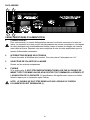
Intended to alert the user to the presence of uninsulated “dangerous voltage” within the product’s
enclosure that may be of sufficient magnitude to constitute a risk of electric shock to persons.
Intended to alert the user of the presence of important operating and maintenance (servicing)
instructions in the literature accompanying the product.
CAUTION: Risk of electrical shock — DO NOT OPEN!
CAUTION: To reduce the risk of electric shock, do not remove cover. No user serviceable parts inside. Refer
servicing to qualified service personnel.
WARNING: To prevent electrical shock or fire hazard, do not expose this appliance to rain or moisture. Before
using this appliance, read the operating guide for further warnings.
Este símbolo tiene el propósito, de alertar al usuario de la presencia de “(voltaje) peligroso” sin aislamiento dentro de la caja del producto y que puede tener una magnitud suficiente como para constituir
riesgo de descarga eléctrica.
Este símbolo tiene el propósito de alertar al usario de la presencia de instruccones importantes sobre la
operación y mantenimiento en la información que viene con el producto.
PRECAUCION: Riesgo de descarga eléctrica ¡NO ABRIR!
PRECAUCION: Para disminuír el riesgo de descarga eléctrica, no abra la cubierta. No hay piezas útiles dentro.
Deje todo mantenimiento en manos del personal técnico cualificado.
ADVERTENCIA: Para evitar descargas eléctricas o peligro de incendio, no deje expuesto a la lluvia o humedad
este aparato Antes de usar este aparato, Iea más advertencias en la guía de operación.
Ce symbole est utilisé dans ce manuel pour indiquer à l’utilisateur la présence d’une tension dangereuse
pouvant être d’amplitude suffisante pour constituer un risque de choc électrique.
Ce symbole est utilisé dans ce manuel pour indiquer à l’utilisateur qu’il ou qu’elle trouvera d’importantes
instructions concernant l’utilisation et l’entretien de l’appareil dans le paragraphe signalé.
ATTENTION: Risques de choc électrique — NE PAS OUVRIR!
ATTENTION: Afin de réduire le risque de choc électrique, ne pas enlever le couvercle. Il ne se trouve à l’intérieur
aucune pièce pouvant être reparée par l’utilisateur. Confiez I’entretien et la réparation de l’appareil à un réparateur
Peavey agréé.
AVERTISSEMENT: Afin de prévenir les risques de décharge électrique ou de feu, n’exposez pas cet appareil à la
pluie ou à l’humidité. Avant d’utiliser cet appareil, lisez attentivement les avertissements supplémentaires de ce
manuel.
Dieses Symbol soll den Anwender vor unisolierten gefährlichen Spannungen innerhalb des Gehäuses
warnen, die von Ausreichender Stärke sind, um einen elektrischen Schlag verursachen zu können.
Dieses Symbol soll den Benutzer auf wichtige Instruktionen in der Bedienungsanleitung aufmerksam
machen, die Handhabung und Wartung des Produkts betreffen.
VORSICHT: Risiko — Elektrischer Schlag! Nicht öffnen!
VORSICHT: Um das Risiko eines elektrischen Schlages zu vermeiden, nicht die Abdeckung enfernen. Es befinden
sich keine Teile darin, die vom Anwender repariert werden könnten. Reparaturen nur von qualifiziertem
Fachpersonal durchführen lassen.
ACHTUNG: Um einen elektrischen Schlag oder Feuergefahr zu vermeiden, sollte dieses Gerät nicht dem Regen
oder Feuchtigkeit ausgesetzt werden. Vor Inbetriebnahme unbedingt die Bedienungsanleitung lesen.
2
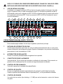
ENGLISH
NITROBASS™
PROFESSIONAL BASS AMPLIFIER
Congratulations on your purchase of the Peavey NitroBass™. The NitroBass includes an easy-touse, three-band active EQ with shiftable mid-range control and a contour control (for that smileyface EQ curve). These tone controls are so versatile you should be able to quickly dial up your own
sound.
Also provided are a buffered tuner send jack, an electronically balanced XLR line out with its own
level control, pre-post EQ switch, and a ground lift switch. The XLR output is before the master
volume control, so you can adjust your stage volume without affecting the send to the main sound
system.
A -10 dB input pad switch, footswitchable post-EQ effects loop, preamp output/power amp input
patch points, and the DDT™ (speaker protection) enable/defeat switch add to the list of professional
features found in the NitroBass.
For more information on operation and specifications we suggest that you spend a few minutes to
look through this manual. Pay close attention to the safety precautions. They contain warnings that
concern the safety of both you and your amp. Thank you for buying Peavey!
Features:
•
•
•
•
•
•
•
•
•
•
•
•
Compact top box design
450 watts into 2 Ω, 300 watts into 4 Ω, 170 watts into 8 Ω
Three-band active EQ with shiftable mid-range control
Contour control
-10 dB pad switch (active/passive pickup switch)
Buffered tuner send jack
Footswitchable post-EQ effects loop
Electronically balanced XLR jack
Pre-/Post-EQ send switch for XLR jack
Ground lift switch for XLR jack
DDT™ speaker protection with defeat switch
Preamp out/power amp in jacks
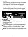
3
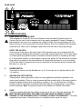
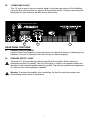
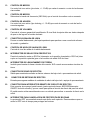
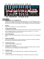
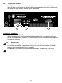
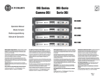
REAR PANEL
4
2
1
3
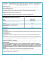
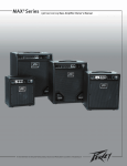
AC POWER FEATURES:
1.
REMOVABLE AC POWER CORD
This receptacle is for the IEC line cord (included), which provides AC power to the unit.
Connect the line cord to this connector and to a properly grounded AC supply. Damage to
the equipment may occur if an improper line voltage is used. (See voltage marking on unit.)
Never remove or cut the ground pin of the line cord plug. This unit is supplied with a properly
rated line cord. When lost or damaged, replace this cord with one of the proper ratings.
NOTE: FOR UK ONLY
As the colors of the wires in the mains lead of this apparatus may not correspond with the
colored markings identifying the terminals in your plug, proceed as follows: (1) The wire which
is colored green and yellow must be connected to the terminal which is marked by the letter
E, or by the earth symbol, or colored green or green and yellow. (2) The wire which is colored
blue must be connected to the terminal which is marked with the letter N, or the color black.
(3) The wire which is colored brown must be connected to the terminal which is marked with
the letter L or color red.
2.
POWER SWITCH
This switch is used to turn the NitroBass on or off. To turn the unit on, flip the switch to the
“on” position.
3.
GROUND POLARITY SWITCH
Three-position, rocker-type switch, which for most applications should be operated in the
center (zero) position. If hum or noise is present with the ground switch in the center position,
place the ground polarity switch to positive or negative (+ or -) to minimize hum; should a
problem continue, consult your authorized Peavey dealer, the Peavey factory, or a qualified
service technician. Note: The ground switch is not available on 220/240 volt models.
4.
FUSE
The fuse is located within the fuse holder on the rear of the unit. If the fuse should fail, IT
MUST BE REPLACED WITH THE SAME TYPE AND VALUE IN ORDER TO AVOID
DAMAGE TO THE EQUIPMENT AND TO PREVENT VOIDING THE WARRANTY. If the amp
repeatedly blows fuses, it should be taken to a qualified service center for repair.
4
NOTE: THE FUSE SHOULD ONLY BE REPLACED WHEN THE REMOVABLE POWER
CORD HAS BEEN DISCONNECTED FROM ITS CHASSIS RECEPTACLE (1).
5.
POWER/STATUS LED
Located on front panel this LED illuminates green when the Power Switch is in the “ON”
position and AC power is supplied. During normal operation the LED also acts as a DDT
indicator. The LED illuminates red when the DDT speaker protection is active. When DDT is
defeated, the LED will illuminate red when clipping occurs.
7
6
9
8
18
10
17
11
19
12
20
13
23
14
15
21
22
16
5
25
26
24
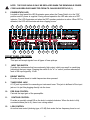
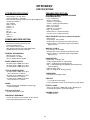
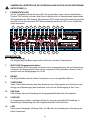
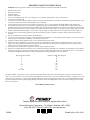
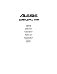
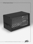
FRONT PANEL FEATURES:
6.
INPUT JACK
This input will accept signals from all types of bass pickups.
7.
INPUT PAD SWITCH
Provided for instruments that have extremely high output, which can result in overdriving
(distorting) the input stage. Pressing the switch to its “in” or “active” position reduces the
level of the input signal by 10 dB.
8.
BRIGHT SWITCH
Provides a preset boost to treble frequencies when pressed.
9.
TUNER SEND JACK
A 1/4" jack is provided for connecting an instrument tuner. This jack is buffered off the input
jack so it is just like plugging directly into the tuner.
10.
PRE GAIN CONTROL
Controls the input gain of the preamplifier.
11.
CONTOUR CONTROL
Provides a specially voiced EQ as the knob is rotated clockwise. When the knob is fully
counterclockwise (set to 0), there is no voicing added.
12.
LOW CONTROL
An active tone control (shelving type, ±15 dB) that varies the low frequency boost or cut.
5
13.
MID CONTROL
An active tone control (peak/notch, ±15 dB) that varies the midrange boost or cut.
14.
MID SHIFT CONTROL
Selects the frequency band (200 — 2 kHz) that the mid control cuts or boosts.
15.
HIGH CONTROL
An active tone control (shelving type, ±15 dB) that varies the high frequency boost or cut.
16.
VOLUME CONTROL
Controls the overall volume level of the amplifier. The final level adjustment should be made
after the desired sound has been achieved.
17.
LINE OUT—XLR JACK
Provides low impedance, electronically balanced signal for patching into a sound
reinforcement or recording console.
18.
LINE OUT LEVEL CONTROL
Controls the output level of the balanced line out.
19.
PRE-/POST-EQ SELECT SWITCH
Allows selection between a Pre-EQ (switch set to the “out” position) or a Post-EQ (switch set
to the “in” position) send to the XLR line out jack.
20.
GROUND LIFT SWITCH
Provided to lift the ground on the XLR jack when ground loops are encountered.
21.
EFFECTS SEND JACK
Output for supplying signals to external low-level effects or signal processing equipment.
22.
EFFECTS RETURN JACK
Input for returning signals from external low-level effects or signal processing equipment.
23.
EFFECTS LOOP REMOTE SWITCH JACK
This jack accommodates the remote footswitch (optional part number 00051000 ON/OFF
single button switch), which is used to remove the effects loop from the signal path. The
remote footswitch essentially acts as a bypass to punch in or punch out from your external
effects.
24.
DDT™ SPEAKER PROTECTION DEFEAT SWITCH
DDT™ speaker protection is defeated when the push button is in the “in” position. We
recommend that DDT be enabled at all times to protect the speakers.
25.
PREAMP OUT JACK
This 1/4" jack is used to route the preamp signal to external inputs, such as the input of an
additional power amp. The signal is post volume control. Use of this jack does not defeat the
signal to the NitroBass amp (some volume difference may be noticed due to the impedance
change experienced when adding an external unit to the signal patch).
6
26.
POWER AMP IN JACK
This 1/4" jack is used to input an external signal to the power amp section of the NitroBass.
Using this jack will disconnect any signal from the preamp section. Using this jack along with
the preamp out jack creates a possible second effects loop.
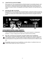
27
28
27
REAR PANEL FEATURES:
27.
POWER CORD RETAINERS
Use the Power Cord Retainers to wrap and store your cable while storing or transporting your
NitroBass. It is best to disconnect the cord from the unit before wrapping.
28.
SPEAKER OUTPUT JACKS
These two 1/4" jacks provide the powered signal from the amplifier. Each connector is
electrically the same (in parallel). Use one of the jacks to connect your speaker cabinet and
the other to add a second speaker cabinet in parallel. The minimum speaker load impedance
is 2 ohms (or two 4-ohm speakers in parallel).
Warning: To prevent the amplifier from overheating, the front fan and rear-located vents
should always remain clear of obstructions.
7
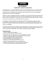
8
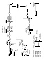
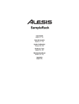
-
Ground Lift
Line Drivers
3
+
Buffer
170 Watts RMS
with 8 Ohm load
300 Watts RMS
with 4 Ohm load
450 Watts RMS
with 2 Ohm load
Minimum Load is
2 Ohms:
1
2
Balanced
Line Out
2
PreGain
Gain
RD
GN Status LED
Green = Pwr On
Red = DDT/Clip
Line Level
1 VRMS, 0dB
PreAmp Out
Full Range
Line Level
1 VRMS, 0dB
Low Shelf
(Bass)
+/- 15 dB
High Shelf
(Treble)
+/- 15 dB
Shelving EQ
Pwr Amp In
Infrasonic
Filter
Buffer/DDT
DDT Defeat
Power Amp
External
Speaker Jack
CW
Contour
Pre EQ
Post EQ
Pre/Post EQ
Select
Line Level
Out
-10 db Pad
In/Out
1
-10 db Pad
Tuner Send
Instrument Level
Input
Bright
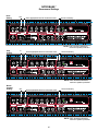
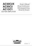
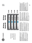
Block Diagram
NITROBASS™
Buffer
Volume CW
Midrange
Cut/Boost
+/- 15 dB
Buffer
Switch Logic
Buffer
Midrange
Shift
200HZ - 2KHZ
Midrange
Effects Loop
Footswitch
Effects
Return
Effects Loop
-10 dB, 0,
315 VRMS
Effects
Send
NITROBASS™
Recommend Settings
Rock
Setting
Out
Set to appropriate level for instrument used
Set as necessary
NOTE: “DDT should be utilized for
maximum speaker protection”
Slap
Setting
In
Set to appropriate level for instrument used
Set as necessary
Doesn't matter when Mid is set to 0
NOTE: “DDT should be utilized for
maximum speaker protection”
Blues/
Country
Setting
Out
Set to appropriate level for instrument used
Set as necessary
NOTE: “DDT should be utilized for
maximum speaker protection”
9
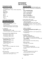
NITROBASS™
SPECIFICATIONS
SYSTEM SPECIFICATIONS:
PREAMPLIFIER SECTION:
Mains Fuse = 8 amps
Mains Voltage = 120 VAC 60 Hz
Power Consumption = 350 watts
Hum and noise: Typically greater than -89 dB unweighted with
controls set as follows…
Pad = Passive
Bright = Normal
Pre gain = 5
Contour = 0
Low = 0
Mid = 0
Mid Shift = 1kHz
High = 0
Volume = 5
SETTINGS FOR MEASUREMENTS UNLESS
OTHERWISE NOTED:
Pad = out (Passive)
Bright = out (Normal)
Pre-Gain = 5 (12 o’clock)
Contour = 0 (fully counterclockwise)
Bass = 0 (12 o’clock)
Mid = 0 (12 o’clock)
Mid Shift = 0 (12 o’clock)
High = 0 (12 o’clock)
Master Volume = 10 (fully Clockwise)
Line Out Level = 10 (fully Clockwise)
INPUT SENSITIVITY (Level to achieve full power):
With Pad Out...
Nominal input: 100 mV RMS
Minimum input: 9 mV(pre gain and master fully CW)
Maximum input: 3.0 V(maximum signal at input before
clipping occurs)
POWER AMPLIFIER SECTION:
PROTECTION:
Electronic current limit protection circuit.
Thermal protection circuit.
D.C. crowbar protection circuit.
DDT speaker protection circuit with defeat switch.
Variable speed fan, thermally controlled
With Pad -10 dB in:
Nominal input: 315 mV RMS
Minimum input: 28 mV (pre gain and master fully CW)
Maximum input: 9 V (maximum signal at input before
clipping occurs)
GENERAL INFORMATION:
Minimum load = 2 ohms
Input sensitivity: 1.0 VRMS
Two 1/4" speaker jacks in parallel
EQUALIZATION:
Bright boost: + 8 dB @ 5 kHz
Contour: Special frequency compensation
Bass: ± 15 dB @ 30 Hz, Shelving type Eq
Mid : ± 15 dB @ 200 @ 2 kHz (Mid shift control determines
center frequency)
Mid Shift: 200 to 2 kHz
High: ±15 dB @ 8 kHz, Shelving type Eq
RATED POWER OUTPUT:
450 watts (30.00 V RMS) into 2 ohms
300 watts (34.64 V RMS) into 4 ohms
170 watts (36.88 V RMS) into 8 ohms
TYPICAL POWER OUTPUT
475 watts (30.82 V RMS) into 2 ohms
with no more than 1% THD+N
308 watts (35.10 V RMS) into 4 ohms
with no more than 1% THD+N
177 watts (37.63 V RMS) into 8 ohms
with no more than 1% THD+N
TUNER SEND:
Instrument level through a buffer
LINE OUT:
-∞ to -10 dB (for nominal input).
Level is dependent on level control setting and pre gain setting
NOISE:
Typically greater than 102 dB below full power @
8 ohms unweighted
EFFECTS LOOP:
Set for -10 dB (0.315 V RMS) with pre @ 5, Master @ 10
Controlled via footswitch, ground tip to defeat.
DDT Dynamic Range:
Typically greater than +15 dB
PREAMP OUTPUT:
1 V RMS nominal
FREQUENCY RESPONSE:
+0/-0.61 dB, 100mW to 160 W RMS, 20 Hz to 20 kHz
(8 ohm load, typically below 0.2% THD+N)
10
ESPAÑOL
NITROBASS™
Amplificador profesional para bajo
Felicitaciones por tu compra del NitroBass™ de Peavey. El NitroBass incluye un ecualizador activo
de tres bandas con control de cambio de medios y control de silueta que es fácil de usar (para
lograr esa curva de ecualización de cara feliz). Estos controles de tono son tan versátiles que
podrás obtener tu sonido muy rápidamente.
También se incluyen entradas de afinador, una salida de nivel de línea XLR balanceada electrónicamente y que tiene su propio control de nivel, control de ecualización pre y post, así como un interruptor de tierra. La salida XLR va antes del control de volumen para que puedas ajustar tu volumen
de escenario sin afectar el envío del sistema de sonido principal.
Un interruptor de pad de 10 dB, circuito de efectos post EQ controlable por pedal, puntos de
parcheo salida de preamp/entrada de ampli de poder, y un interruptor activar/cancelar para el sistema DDT™ de protección de bocinas se añaden a la lista de características profesionales encontradas en el NitroBass.
Para más información sobre la operación y las especificaciones te sugerimos que tomes unos minutos para leer este manual. Presta mucha atención a las precauciones de seguridad. Contienen avisos que conciernen tu seguridad y la de tu ampli. ¡Gracias por comprar Peavey!
Características:
•
•
•
•
•
•
•
•
•
•
•
Diseño compacto de caja superior
450 wats a 2 ,Ω 300 wats a 4 ,Ω 170 wats a 8 .Ω
Ecualizador activo de tres bandas con control cambiable de medios
Interruptor de pad de 10dB (interruptor de pastilla activa/no-activa)
Conector amortiguado para envío de afinador
Circuito de efectos por EQ controlable por pedal
Entrada XLR balanceada electrónicamente
Interruptor de envío para salida XLR Pre-/post EQ
Interruptor de levantamiento de tierra para salida XLR
Protección para bocinas DDT™ con interruptor de cancelación
Conectores salida de preamp/entrada de ampli de poder
11
4
2
1
3
CARACTERÍSTICAS DE PODER CA:
1.
CABLE DE PODER CA INTERCAMBIABLE
Esta entrada es para el cable de línea IEC (incluido), mismo que provee poder CA a la
unidad. Conecta el cable de línea a este conector y a un suministro de CA propiamente aterrizado. El equipo puede dañarse si se usa voltaje de línea inapropiado. (Ver marcación de
voltaje en la unidad). Nunca quites ni cortes el alfiler de tierra del conector del cable de línea.
Esta unidad viene con un cable de marcación correcta. Si se pierde o daña el cable, reemplázalo con uno de las marcaciones correcta.
NOTA: PARA EL REINO UNIDO SOLAMENTE
Ya que los colores de los cables en la sección maestra de este aparato pueden no corresponder a las marcaciones de colores que identifiquen las unidades de tu conector, procede
como sigue: (1) El cable de color verde y amarillo debe ser conectado a la terminal que está
marcada con la letra E, o por el símbolo de tierra, o del color verde o verde y amarillo. (2) El
cable de color azul debe conectarse a la terminal marcada con la letra N, o el color negro. (3)
El cable de color café debe conectarse a la terminal marcada con la letra L o el color rojo.
2.
INTERRUPTOR DE PODER
Éste es usado para encender o apagar el NitroBass. Para encender la unidad, pon el interuptor en la posición on.
3.
INTERRUPTOR DE POLARIDAD DE TIERRA
Un interruptor de tres posiciones, tipo mecedora, que para la mayoría de las aplicaciones
debe ser operado en la posición central (cero). Si se presenta ruido o hum con el interruptor
en la posición central, coloca el interruptor hacia el positivo o negativo (+ o -) para minimizar
el ruido; si el problema continuase consulta con tu vendedor autorizado de Peavey, la fábrica
Peavey, o un técnico de servicio calificado. Nota: El interruptor de tierra no está disponible
en los modelos de 220/240 voltios.
4.
FUSIBLE
El fusible está localizado dentro del compartimento de fusible en la parte trasera de la
unidad. Si el fusible fallase, DEBE SER REEMPLAZADO CON UNO DEL MISMO TIPO,
CALIDAD Y VALOR PARA PODER EVITAR CUALQUIER DAÑO A LA UNIDAD Y PARA
QUE NO SE CANCELE LA GARANTÍA. Si el ampli quema fusibles continuamente, debe ser
llevado a un centro de servicio calificado para su reparación.
12
NOTA: EL FUSIBLE SÓLO DEBE SER REEMPLAZADO CUANDO EL CABLE DE CORRIENTE HAYA SIDO DESCONECTADO DE SU RECEPTÁCULO EN EL CHASÍS (1).
5.
LED DE ESTADO DE PODER
Localizado en el panel frontal este LED se ilumina de verde cuando el interruptor de poder
esté en la posición ON y se esté suministrando poder CA. Durante la operación normal el
LED también actúa como indicador de DDT. El LED se iluminará de rojo cuando esté activada la protección de bocinas DDT. Cundo se cancele la DDT, el LED se iluminará de rojo si
ocurre la saturación.
7
6
9
8
18
10
17
11
19
12
20
13
23
14
21
15
22
16
5
25
26
24
CARACTERÍSTICAS DEL PANEL FRONTAL:
6.
CONECTOR DE ENTRADA
Esta entrada acepta señales de todo tipo de pastillas (micrófonos) de bajo.
7.
ENTRADA DE INTERRUPTOR DE PAD
Incluido para instrumento que tienen un nivel de salida extremadamente alto, la cual puede
causar es distorsión en la etapa de entrada. Oprime el interruptor a su posición de activación
para reducir el nivel de entrada por 10 dB.
8.
INTERRUPTOR DE BRILLANTEZ
Provee un aumento predeterminado de agudos al ser oprimido.
9.
CONECTOR DE ENVÍO A AFINADOR
Una entrada de 1/4 se incluye para conectar un afinador de instrumento. Este conector es
paralelo al de entrada para que la conexión se haga directamente al afinador.
10.
CONTROL DE PRE-GANANCIA
Controla la ganancia de entrada del preamplificador.
11.
CONTROL DE SILUETA
Provee un ecualizador ajustado especialmente al ir girando la perilla hacia la derecha.
Cuando la perilla está totalmente hacia la izquierda (en 0), no hay ecualización añadida.
12.
CONTROL DE GRAVES
Un control de tono activo (tipo shelving, +/-15 dB) que varía el aumento o corte de la frecuencia grave.
13
13.
CONTROL DE MEDIOS
Un control de tono activo (pico/corte, +/- 15 dB) que varía el aumento o corte de las frecuencias medias.
14.
CONTROL DE MEDIOS
Selecciona la banda de frecuencia (200-2kHz) que el control de medios corta o aumenta.
15.
CONTROL DE AGUDOS
Un control de tono activo (tipo shelving, +/- 15 dB) que varía el aumento o corte de las frecuencias agudas.
16.
CONTROL DE VOLUMEN
Controla el volumen general del amplificador. El nivel final de ajuste debe ser hecho después
de que se ha logrado el sonido deseado.
17.
CONECTOR XLRSALIDA DE LÍNEA
Provee un señal balanceada y de baja impedancia para parchar a una consola de refuerzo
de sonido o grabación.
18.
CONTROL DE NIVEL DE SALIDA DE LÍNEA
Controla el nivel de salida de la salida balanceada.
19.
INTERRUPTOR DE SELLECCIÓN PRE/POST EQ
Permite la selección entre un EQ-Pre (interruptor en la posición levantada) o EQ-Post (interruptor en la posición oprimida) que va al conector de salida XLR de línea.
20.
INTERRUPTOR DE LEVANTAMIENTO DE TIERRA
Incluido para levantar la tierra a través del conector XLR cuando se encuentran circuitos de
tierra.
21.
CONECTOR DE ENVÍO DE EFECTOS
Salida para suministrar señales a efectos externos de bajo nivel o procesadores de señal.
22.
CONECTOR DE RETORNO DE EFECTOS
Entrada para regresar señales de unidades de efecto de bajo nivel o equipo de procesamiento.
23.
CONECTOR PARA INTERRUPTOR REMOTO DE CIRCUITO DE EFECTOS
Este conector sirve para el pedal remoto (parte opcional número 00051000/interruptor
ON/OFF de botón sencillo), que es usado para quitar el circuito de efecto del paso de señal.
El pedal remoto actúa esencialmente como un método para activar o cancelar el efecto en la
señal.
24.
INTERRUPTOR PARA CANCELACIÓN DE PROTECCIÓN DE BOCINAS
La protección DDT es cancelada cuando este botón esté oprimido. Recomendamos que se
active la DDT todo el tiempo para proteger las bocinas.
14
25.
CONECTOR DE SALIDA DE PREMPLI
Este conector de 1/4 se usa para enviar la señal del preampli a las entradas externas, como
la entrada de un ampli de poder adicional. La señal es post control de volumen. El uso de
este conector no cancela la señal del ampli NitroBass (puede notarse alguna diferencia de
volumen a causa del cambio de impedancia que sucede al añadirse una unidad externa a la
señal).
26.
ENTRADA DE AMPLI DE PODER
Esta entrada de 1/4 se usa para recibir una señal externa a la sección de ampli de poder del
NitroBass. El uso de este conector desconectará cualquier señal de la sección de preamp. El
uso de este conector junto al de la salida de preamp puede causar un segundo circuito de
efecto.
27
28
27
CARACTERÍSTICAS DEL PANEL TRASERO:
27.
RETENCIÓN PARA CABLE DE PODER
Usa los retenedores para enrollar y guardar tu cable cuando transportes o almacenes tu
NitroBass. Lo mejor es desconectar el cable de la unidad antes de enrollarlo.
28.
Estos dos conectores de 1/4 proveen una señal de poder para el amplificador.
Cada conector es igual eléctricamente (en paralelo). Usa uno de los conectores para conectar tu gabinete de bocina y otro para añadir un segundo gabinete de bocina en paralelo. La
mínima impedancia de carga de bocina es de 2 ohmios (o dos bocinas de 4 ohmios en paralelo).
Precaución: para prevenir que el amplificador se sobre caliente, el ventilador frontal y las
ventilas traseras deben estar libres de obstrucción.
15
16
-
Ground Lift
Line Drivers
3
+
Buffer
170 Watts RMS
with 8 Ohm load
300 Watts RMS
with 4 Ohm load
450 Watts RMS
with 2 Ohm load
Minimum Load is
2 Ohms:
1
2
Balanced
Line Out
2
PreGain
Gain
RD
GN Status LED
Green = Pwr On
Red = DDT/Clip
Line Level
1 VRMS, 0dB
PreAmp Out
Full Range
Line Level
1 VRMS, 0dB
Low Shelf
(Bass)
+/- 15 dB
High Shelf
(Treble)
+/- 15 dB
Shelving EQ
Pwr Amp In
Infrasonic
Filter
Buffer/DDT
DDT Defeat
Power Amp
External
Speaker Jack
CW
Contour
Pre EQ
Post EQ
Pre/Post EQ
Select
Line Level
Out
-10 db Pad
In/Out
1
-10 db Pad
Tuner Send
Instrument Level
Input
Bright
Block Diagram
NITROBASS™
Buffer
Volume CW
Midrange
Cut/Boost
+/- 15 dB
Buffer
Switch Logic
Buffer
Midrange
Shift
200HZ - 2KHZ
Midrange
Effects Loop
Footswitch
Effects
Return
Effects Loop
-10 dB, 0,
315 VRMS
Effects
Send
NITROBASS™
Recommend Settings
Rock
Setting
Out
Set to appropriate level for instrument used
Set as necessary
NOTE: “DDT should be utilized for
maximum speaker protection”
Slap
Setting
In
Set to appropriate level for instrument used
Set as necessary
Doesn't matter when Mid is set to 0
NOTE: “DDT should be utilized for
maximum speaker protection”
Blues/
Country
Setting
Out
Set to appropriate level for instrument used
Set as necessary
NOTE: “DDT should be utilized for
maximum speaker protection”
17
NITROBASS™
ESPECIFICACIONES
ESPECIFICACIONES DEL SISTEMA
SECCIÓN DE PREAMPLIFICADOR:
Fusible principal = 8 amps
Voltaje = 120 VAC 60 Hz
Consumo de poder = 350 wats
Hum y ruido: Típicamente mayor que -89 dB
sin peso con controles ajustados como sigue:
Pad = pasivo
Brillante = Normal
Pre ganancia = 5
Silueta = 0
Graves = 0
Medios = 0
Cambio de Medios = 1kHz
Agudos = 0
Volumen = 5
VALORES PARA MEDIDAS AL MENOS QUE SE INDIQUE
LO CONTRARIO:
Pad = salida (pasivo)
Brillante = salida (Normal)
Pre-gnancia = 5 (12 en el reloj)
Silueta = 0 (totalmente hacia la derecha)
graves = 0 (12 en el reloj)
medios = 0 (12 en el reloj)
Cambio de medios = 0 (12 en el reloj)
Agudos = 0 (12 en el reloj)
Volumen maestro = 10 (totalmente hacia la derecha)
Nivel de Salida de Línea = 10 (totalmente hacia la derecha)
SENSIBILIDAD DE ENTRADA (Nivel para lograr nivel
máximo):
SECCIÓN DE AMPLIFICADOR DE PODER:
Con pad hacia afuera
Entrada nominal: 100 mV RMS
Entrada mínima: 9 mV(pre ganancia y master totalmente
hacia la derecha)
Entrada máxima: 3.0 V(señal máxima de entrada antes de
ocurrir saturación)
Con Pad -10 dB de entrada:
Entrada Nominal: 315 mV RMS
Entrada mínima: 28 mV (pre ganancia y master totalmente
hacia la derecha)
Entrada máxima: 9 V (señal máxima de entrada antes de
ocurrir saturación)
PROTECCIÓN:
Circuito de protección de límite de corriente electrónica
Circuito de protección termal
Circuito de protección de barra de C.D.
Circuito de protección de bocina DDT
con interruptor de cancelación
Ventilador de velocidad variable,
con control por temperatura
INFORMACIÓN GENERAL:
Carga mínima = 2 ohmios
Sensibilidad de entrada: 1.0 VRMS
Dos conectores de bocina de 1/4" en paralelo
ECUALIZACIÓN:
Aumento de brillantez: + 8 dB @ 5 kHz
Silueta: Compensación especial de frecuencia
Graves: ± 15 dB @ 30 Hz, Ecualizador tipo shelving
medios : ± 15 dB @ 200 @ 2 kHz (cambio de medios determina frecuencia central)
cambio de medios: 200 a 2 kHz
Agudos: ±15 dB @ 8 kHz, Ecualizador tipo shelving
ENVÍO DE AFINADOR:
Nivel de instrumento a través de un buffer
PODER CLASIFICADO DE SALIDA:
450 wats (30.00 V RMS) a 2 ohmios
300 wats (34.64 V RMS) a 4 ohmios
170 wats (36.88 V RMS) a 8 ohmios
PODER TÍPICO DE SALIDA
475 wats (30.82 V RMS) a 2 ohmios
con no más de 1% THD+N
308 wats (35.10 V RMS) a 4 ohmios
con no más de 1% THD+N
177 wats (37.63 V RMS) a 8 ohmios
con no más de 1% THD+N
SALIDA DE LÍNEA:
-∞ to -10 dB (para enterada nominal).
El nivel es dependiente del valor del control de nivel y del
valor de pre-ganancia.
RUIDO:
CIRCUITO DE EEFCTOS:
Típicamente mayor que 102 dB abajo
del poder máximo @ 8 ohmios sin peso
Ajustado pra -10 dB (0.315 V RMS) con pre @ 5, Master @ 10
Controlado a través del pedal, punta de tierra para cancelar
Rango Dinámico DDT:
SALIDA DE PREAMP:
Típicamente mayor que +15 dB
1 V RMS nominal
RESPUESTA DE FRECUENCIA:
+0/-0.61 dB, 100mW a 160 W RMS, 20 Hz a 20 kHz
(carga de 8 ohmios, típicamente menor que 0.2% THD+N)
18
FRANCAIS
NITROBASS™
AMPLIFICATEUR BASSE
Nous vous félicitons pour l’achat de cet amplificateur Peavey NitroBass™. Le NitroBass possède un
EQ actif 3-bandes avec réglage semi-paramétrique des mediums et un contrôle de contour (pour
obtenir aisément la populaire equalisation en V). Ces contrôles de tonalité assurent au NitroBass
une versatilité optimum qui vous permettra de trouver rapidement votre son.
Vous disposez en plus d’une sortie accordeur et d’une sortie Line Out XLR symétrique (a
transformateur) avec controle de niveau, sélecteur Pré/Post EQ et sélecteur Ground Lift. Cette sortie
est située avant le Master Volume; vous pouvez donc ajuster votre volume sur scène sans affecter
le signal envoyé a la sonorisation.
Atténuateur de -10 dB désengageable en entrée, boucle d’effet post-EQ enclenchable par
footswitch, sortie préampli ,entrée ampli de puissance et compression DDT complètent la liste des
équipements du NitroBass.
Pour plus d’informations sur le NitroBass, nous vous conseillons de lire attentivement ce manuel.
Veuillez lire attentivement les messages de précautions de ce manuel pour votre propre sécurité et
celle de votre matériel. Merci d’avoir choisi Peavey.
Caracteristiques:
•
•
•
•
•
•
•
•
•
•
•
•
Format tête d’ampli
450 watts sous 2 Ω, 300 watts sous 4 Ω, 170 watts sous 8 Ω
EQ 3-bandes actif avec medium semi-paramétrique
Controle de Contour
Attenuateur -10 dB en entree (instrument actif/passif)
Sortie accordeur
Boucle d’effet post-EQ commutable
Sortie Line Out symétrique XLR
Sélecteur Pré-/Post-EQ pour la sortie XLR
Sélecteur Ground lift pour la sortie XLR
Limiteur DDT™ (protection des HP) avec sélecteur
Connexions Préamp out/Power-amp in
19
FACE ARRIERE
4
2
1
3
CARACTERISTIQUES D’ALIMENTATION:
1.
CONNECTEUR IEC
Pour votre securite, un cordon d’alimentation assurant une bonne connexion a la terre est
inclus. La connexion a la terre ne doit etre deconnectee en aucune circonstance. Les risques
de choc electrique sont considerablement reduits lorsque la masse du chassis est correcte
ment reliee a la terre. Reportez-vous aux inscriptions au dos de votre amplificateur pour la
tension d’alimentation necessaire.
2.
INTERRUPTEUR DE MISE SOUS TENSION
Permet de mettre le NitroBass sous tension. Pour cela, placer l’interrupteur sur “on”.
3.
SELECTEUR DE POLARITE DE LA MASSE
Absent sur les versions europeennes.
4.
FUSIBLE
Si le fusible grille, IL DOIT ETRE IMPERATIVEMENT REMPLACE PAR UN FUSIBLE DE
MEME TYPE ET DE MEME VALEUR AFIN D’EVITER TOUT DOMMAGE A L’APPAREIL ET
L’ANNULATION DE LA GARANTIE. Si l’amplificateur fait régulièrement sauter son fusible,
faites-le réparer par un réparateur agréé Peavey.
NOTE: LE FUSIBLE NE DOIT ETRE REMPLACE QUE LORSQUE LE CORDON
D’ALIMENTATION EST DEBRANCHE (1).
20
7
6
9
8
18
10
17
11
19
12
20
13
23
14
15
21
22
16
5
25
26
24
FACE AVANT:
5.
LED DE STATUT ET D’ALIMENTATION
Lorsque le commutateur d'alimentation est sur la position "on", la LED s'illumine en vert.
Cette LED joue aussi le rôle d'indicateur DDT. Elle deviendra rouge si la compression DDT se
met en action. Si la DDT n'est pas utlisée, la LED s'illuminera en rouge en cas d'écrêtage.
6.
ENTREE
Cette entrée fonctionne pour tous les types de basses.
7.
ATTENUATEUR D’ENTREE
Cet atténuateur est destiné aux instruments à haut niveau de sortie pouvant causer une saturation (ecrêtage) indésirable. En plaçant le sélecteur dans sa position “in” ou “active” le
niveau du signal d'entrée est réduit de 10 dB.
8.
SELECTEUR BRIGHT
Assure un boost des fréquences aigues. Placez le sélecteur en position “in” pour engager le
boost.
9.
SORTIE ACCORDEUR
Une prise jack est fournie pour une sortie accordeur. Le niveau de la sortie est compensé
pour assurer un fonctionnement parfait de l'accordeur.
10.
CONTROLE PRE GAIN
Contrôle le gain d'entrée de l'amplificateur.
11.
CONTROLE DE CONTOUR
Fait intervenir un voicing préétabli en tournant le contrôle dans le sens horaire. Lorsque le
contrôle est à 0, aucun voicing ne colore le son de l'ampli.
12.
CONTROLE LOW
Contrôle de tonalité actif (±15 dB) augmentant ou atténuant les fréquences graves.
13.
CONTROLE MID
Contrôle de tonalité actif (±15 dB) augmentant ou atténuant les fréquences moyennes.
21
14.
CONTROLE MID SHIFT
Détermine la bande de fréquences sur laquelle agît le contrôle mid.
15.
CONTROLE HIGH
Contrôle de tonalité actif (±15 dB) augmentant ou atténuant les fréquences aigues.
16.
CONTROLE VOLUME
Détermine le volume général de l'amplificateur. Ce contrôle doit être ajusté une fois que le
son recherché a été obtenu.
17.
LINE OUT—XLR JACK
Offre une sortie à 600 Ohm symétrique pour connectez la tête à un système de sonorisation
ou d'enregistrement.
18.
CONTROLE LINE OUT LEVEL
Détermine le niveau de sortie de la connexion Line Out (17).
19.
SELECTEUR PRE-/POST-EQ SELECT
Permet de sélectionner le positionnement de la sortie Line Out: Pré-EQ (sélecteur en position
"Out") ou Post-EQ (sélecteur en position "in").
20.
SELECTEUR GROUND LIFT
Permet de déconnecter la masse de la sortie Line Out pour combattre les problèmes de
boucle de masse éventuels.
21.
SORTIE EFFECTS SEND
Sortie fournissant un signal bas niveau pour des effets ou processeurs externes.
22.
ENTREE EFFECTS RETURN
Retour des signaux bas niveau provenant d'effets ou processeurs externes.
23.
PRISE DE PEDALE DE COMMANDE DE LA BOUCLE D’EFFET
Cette prise est destinée au footswitch (optionel simple action ref n°00051000) retirant la
boucle d'effet du chemin du signal. La pédale de commande permet d'engager et désengager
vos effets externes.
24.
INTERRUPTEUR DE LA PROTECTION DES HPS DDT™
Lorsque le sélecteur est en position "in", la compression DDT™ est désengagée. Nous
recommandons de toujours laisser la compression DDT engagée afin de protéger les hautparleurs.
25.
SORTIE PREAMP OUT
Cette sortie permet de connecter la sortie du préampli à des unités externes tel un ampli de
puissance supplémentaire. Le sortie est située aprés le contrôle de volume. Lors de l'utilisation de cette connexion, le signal du préampli reste acheminé à l'ampli du FireBass 700 (une
différence de volume dûe à un changement d'impédance issu de la connexion à une autre
unité peut être perçue).
22
26.
POWER AMP IN JACK
This 1/4" jack is used to input an external signal to the power amp section of the NitroBass.
Using this jack will disconnect any signal from the preamp section. Using this jack along with
the preamp out jack creates a possible second effects loop.
27
28
27
PANNEAU ARRIERE:
27.
PATTES D’ENROULEMENT
Utilisez ces pattes pour enrouler votre cordon d'alimentation lors du rangement ou du transport de votre amplificateur FireBass 700. Déconnectez le cordon d'alimentation de l'amplificateur avant de l'enrouler.
28.
SORTIES HP
Ces deux prises jacks constituent la sortie de l'amplificateur. Ces deux sorties sont identiques
et connectées en parallèle. L'impédance minimum en sortie de l'amplificateur doit être de 2
Ohm (soit deux enceintes de 4 Ohm en parallèle).
ATTENTION: Pour éviter toute surchauffe de l'amplificateur, le ventilateur et les évents
d'aération ne doivent en aucun cas être obstrués.
23
24
-
Ground Lift
Line Drivers
3
+
Buffer
170 Watts RMS
with 8 Ohm load
300 Watts RMS
with 4 Ohm load
450 Watts RMS
with 2 Ohm load
Minimum Load is
2 Ohms:
1
2
Balanced
Line Out
2
PreGain
Gain
RD
GN Status LED
Green = Pwr On
Red = DDT/Clip
Line Level
1 VRMS, 0dB
PreAmp Out
Full Range
Line Level
1 VRMS, 0dB
Low Shelf
(Bass)
+/- 15 dB
High Shelf
(Treble)
+/- 15 dB
Shelving EQ
Pwr Amp In
Infrasonic
Filter
Buffer/DDT
DDT Defeat
Power Amp
External
Speaker Jack
CW
Contour
Pre EQ
Post EQ
Pre/Post EQ
Select
Line Level
Out
-10 db Pad
In/Out
1
-10 db Pad
Tuner Send
Instrument Level
Input
Bright
Block Diagram
NITROBASS™
Buffer
Volume CW
Midrange
Cut/Boost
+/- 15 dB
Buffer
Switch Logic
Buffer
Midrange
Shift
200HZ - 2KHZ
Midrange
Effects Loop
Footswitch
Effects
Return
Effects Loop
-10 dB, 0,
315 VRMS
Effects
Send
NITROBASS™
Recommend Settings
Rock
Setting
Out
Set to appropriate level for instrument used
Set as necessary
NOTE: “DDT should be utilized for
maximum speaker protection”
Slap
Setting
In
Set to appropriate level for instrument used
Set as necessary
Doesn't matter when Mid is set to 0
NOTE: “DDT should be utilized for
maximum speaker protection”
Blues/
Country
Setting
Out
Set to appropriate level for instrument used
Set as necessary
NOTE: “DDT should be utilized for
maximum speaker protection”
25
NITROBASS™
SPECIFICATIONS
SYSTEM SPECIFICATIONS:
PREAMPLIFIER SECTION:
Mains Fuse = 8 amps
Mains Voltage = 120 VAC 60 Hz
Power Consumption = 350 watts
Hum and noise: Typically greater than -89 dB unweighted with
controls set as follows…
Pad = Passive
Bright = Normal
Pre gain = 5
Contour = 0
Low = 0
Mid = 0
Mid Shift = 1kHz
High = 0
Volume = 5
SETTINGS FOR MEASUREMENTS UNLESS
OTHERWISE NOTED:
Pad = out (Passive)
Bright = out (Normal)
Pre-Gain = 5 (12 o’clock)
Contour = 0 (fully counterclockwise)
Bass = 0 (12 o’clock)
Mid = 0 (12 o’clock)
Mid Shift = 0 (12 o’clock)
High = 0 (12 o’clock)
Master Volume = 10 (fully Clockwise)
Line Out Level = 10 (fully Clockwise)
INPUT SENSITIVITY (Level to achieve full power):
With Pad Out...
Nominal input: 100 mV RMS
Minimum input: 9 mV(pre gain and master fully CW)
Maximum input: 3.0 V(maximum signal at input before
clipping occurs)
POWER AMPLIFIER SECTION:
PROTECTION:
Electronic current limit protection circuit.
Thermal protection circuit.
D.C. crowbar protection circuit.
DDT speaker protection circuit with defeat switch.
Variable speed fan, thermally controlled
With Pad -10 dB in:
Nominal input: 315 mV RMS
Minimum input: 28 mV (pre gain and master fully CW)
Maximum input: 9 V (maximum signal at input before
clipping occurs)
GENERAL INFORMATION:
Minimum load = 2 ohms
Input sensitivity: 1.0 VRMS
Two 1/4" speaker jacks in parallel
EQUALIZATION:
Bright boost: + 8 dB @ 5 kHz
Contour: Special frequency compensation
Bass: ± 15 dB @ 30 Hz, Shelving type Eq
Mid : ± 15 dB @ 200 @ 2 kHz (Mid shift control determines
center frequency)
Mid Shift: 200 to 2 kHz
High: ±15 dB @ 8 kHz, Shelving type Eq
RATED POWER OUTPUT:
450 watts (30.00 V RMS) into 2 ohms
300 watts (34.64 V RMS) into 4 ohms
170 watts (36.88 V RMS) into 8 ohms
TYPICAL POWER OUTPUT
475 watts (30.82 V RMS) into 2 ohms
with no more than 1% THD+N
308 watts (35.10 V RMS) into 4 ohms
with no more than 1% THD+N
177 watts (37.63 V RMS) into 8 ohms
with no more than 1% THD+N
TUNER SEND:
Instrument level through a buffer
LINE OUT:
-∞ to -10 dB (for nominal input).
Level is dependent on level control setting and pre gain setting
NOISE:
Typically greater than 102 dB below full power @
8 ohms unweighted
EFFECTS LOOP:
Set for -10 dB (0.315 V RMS) with pre @ 5, Master @ 10
Controlled via footswitch, ground tip to defeat.
DDT Dynamic Range:
Typically greater than +15 dB
PREAMP OUTPUT:
1 V RMS nominal
FREQUENCY RESPONSE:
+0/-0.61 dB, 100mW to 160 W RMS, 20 Hz to 20 kHz
(8 ohm load, typically below 0.2% THD+N)
26
DEUTSCH
NITROBASS™
PROFESSIONELLER BASS-VERSTÄRKER
Wir freuen uns, dass Sie sich für einen Peavey NitroBass™-Bassverstärker entschieden haben. Die
Klangregelung des NitroBass besteht aus einem aktiven Dreiband-EQ mit parametrischer
Mittenregelung sowie einem zusätzlichen Contour-Regler (für die typische EQ-"U-Form") und ist
damit so vielseitig, dass Sie Ihren Sound schnell gefunden haben dürften. Der NitroBass ist also
sofort startklar!
Darüber hinaus ist der NitroBass mit einer unabhängigen Anschlussbuchse für ein Stimmgerät,
einem elektronisch symmetrierten XLR-Line-Ausgang mit separatem Pegelregler, Pre/Post-EQSchalter und einem Ground-Lift-Schalter ausgestattet. Der XLR-Ausgang befindet sich im
Schaltkreis vor dem Master-Volume-Regler, d.h. Sie können auf der Bühne die Lautstärke verändern, ohne dadurch den Send-Pegel für die PA zu beeinflussen.
Komplettiert wird diese professionelle Ausstattung durch einen -10dB-Eingangswahlschalter, eine
fußschaltbare Post-EQ-Effektschleife, Vorverstärker-Ausgang/Endstufen-Eingang und die abschaltbare DDT™-Lautsprecher-Schutzschaltung.
Weitere Informationen zu Bedienung und Technischen Daten finden Sie in vorliegender
Bedienungsanleitung. Wir empfehlen, diese – und insbesondere die Sicherheitshinweise – sorgfältig
zu lesen. Sie enthält Informationen, die sowohl Ihre Sicherheit als auch die des Geräts betreffen.
Bleibt nur noch, Ihnen zum Kauf Ihres Peavey-Verstärkers zu gratulieren!
Eigenschaften:
•
•
•
•
•
•
•
•
•
•
•
•
Kompaktes Top-Teil
450 Watt an 2 ,Ω 300 Watt an 4 ,Ω 170 Watt an 8 Ω
Aktiver Dreiband-EQ mit parametrischer Mittenregelung
Contour-Regler
-10 dB-Schalter (für Instrumente mit aktiven bzw. passiven Tonabnehmern)
Unabhängige Tuner-Anschlussbuchse
Per Fußschalter steuerbare Post-EQ-Effektschleife
Elektronisch symmetrierter XLR-Ausgang
Pre/Post-EQ-Schalter (XLR-Ausgang)
Ground-Lift-Schalter (XLR-Ausgang)
Abschaltbare DDT™-Lautsprecher-Schutzschaltung
Vorverstärker-Ausgang/Endstufen-Eingang
27
4
2
1
3
STROMVERSORGUNG:
1.
Separates Netzkabel
Diese Buchse ist für das Euro-Netzkabel zur Stromversorgung des Geräts (im Lieferumfang
enthalten) vorgesehen. Schließen Sie das Netzkabel ausschließlich an einen korrekt geerdeten Netzanschluss mit geeigneter Spannung an (siehe Aufschrift Geräterückseite), da das
Gerät sonst ernstlichen Schaden nehmen kann. Entfernen oder umgehen Sie niemals den
Massepunkt am Netzkabel selbst. Bei Auslieferung liegt dem Gerät ein geeignetes Netzkabel
bei. Tauschen Sie dieses im Service-Fall ausschließlich gegen ein gleichermaßen geeignetes
Kabel aus.
ANMERKUNG (GILT NUR FÜR GROSSBRITANNIEN):
Falls die farbliche Kennzeichnung der einzelnen Leiter nicht mit den Kennzeichnungen am
Stecker übereinstimmt, verfahren Sie wie folgt: (1) Schließen Sie den grün-gelben Leiter an
den mit dem Buchstaben E, dem Erdsymbol oder dem grün bzw. grün-gelb gekennzeichneten
Pol an. (2) Schließen Sie den blauen Leiter an den mit dem Buchstaben N oder schwarz
gekennzeichneten Pol an. (3) Schließen Sie den braunen Leiter an den mit dem Buchstaben
L oder rot gekennzeichneten Pol an.
2.
POWER (Netzschalter)
Mit diesem Schalter schalten Sie den NitroBass ein (Position"On") oder aus.
3.
GROUND POLARITY (Polaritätswahlschalter)
Für die meisten Anwendungen sollte sich dieser Dreifach-Wippschalter in Mittelposition
(Nullposition) befinden. Eventuelles Brummen lässt sich durch Umschalten des
Polaritätswahlschalters in die positive (+) bzw. negative (-) Position minimieren. Bei anhaltenden Brummproblemen wenden Sie sich an einen Peavey-Vertragshändler, direkt an
Peavey oder an einen qualifizierten Service-Techniker. Anmerkung: Der Polaritätswahlschalter
ist bei 220/240-Volt-Modellen nicht vorgesehen.
4.
FUSE (Sicherung)
Die Sicherung befindet sich in der Sicherungshalterung auf der Geräterückseite. Sollte die
Sicherung einmal auslösen, ist es UNBEDINGT ERFORDERLICH, SIE DURCH EINE GLEICHARTIGE SICHERUNG ZU ERSETZEN, DA DAS GERÄT SONST ERNSTLICHEN
SCHADEN NEHMEN KANN UND DARÜBER HINAUS IHR GARANTIEANSPRUCH ERLISCHT. Falls die Sicherung wiederholt auslöst, sollten Sie das Gerät unbedingt durch einen
qualifizierten Service-Techniker überprüfen lassen.
28
ANMERKUNG: ERSETZEN SIE DIE SICHERUNG AUSSCHLIESSLICH BEI GEZOGENEM
NETZSTECKER (1).
5.
POWER/STATUS-LED
Auf der Frontplatte befindet sich eine LED, die grün leuchtet, wenn sich der Netzschalter in
Position "ON" befindet und dem Gerät Strom zugeführt wird. Im Normalbetrieb fungiert diese
LED gleichzeitig als DDT-Anzeige. Bei aktivierter DDT-Lautsprecher-Schutzschaltung leuchtet
die LED rot; bei nicht aktivierter DDT-Schutzschaltung leuchtet die LED rot auf, sobald das
Gerät übersteuert.
7
6
9
8
18
10
17
11
19
12
20
13
23
14
21
15
22
16
5
25
26
24
FRONTPLATTE:
6.
INPUT (Eingang)
Der Eingang des NitroBass eignet sich für alle Arten von Bass-Tonabnehmern.
7.
INPUT PAD (Eingangswahlschalter)
Dieser Schalter ist für Instrumente mit extrem hoher Ausgangsleistung, die zum Übersteuern
(Verzerren) der Eingangsstufe führen würde, vorgesehen. Bei gedrücktem Schalter ("aktiv")
reduziert sich der Eingangspegel um 10 dB.
8.
BRIGHT
Der Bright-Schalter hebt die hohen Frequenzen um ein voreingestelltes Maß an.
9.
TUNER SEND
Diese 6,3mm-Klinkenbuchse dient dem Anschluss eines Stimmgeräts und funktioniert unabhängig vom Klinkeneingang des Verstärkers, wirkt also als Direkteingang für den Tuner.
10.
PRE GAIN
Dieser Regler dient der Einstellung der Eingangsempfindlichkeit des Vorverstärkers.
11.
CONTOUR
Im Uhrzeigersinn gedreht, sorgt dieser Regler für eine ganz spezielle EQ-Einstellung. In
Nullstellung (Linksanschlag) wird die Klangcharakteristik nicht beeinflusst.
12.
LOW
Dieser aktive Klangregler (Shelving-Filter, ±15 dB) dient der Anhebung bzw. Absenkung der
tiefen Frequenzen.
29
13.
MID
Dieser aktive Klangregler (Peak/Notch-Filter, ±15 dB) dient der Anhebung bzw. Absenkung
der mittleren Frequenzen.
14.
MID SHIFT
Dieser Regler dient der Einstellung der Eckfrequenz (200 Hz — 2 kHz) für den MID-Regler.
15.
HIGH
Dieser aktive Klangregler (Shelving-Filter, ±15 dB) dient der Anhebung bzw. Absenkung der
hohen Frequenzen.
16.
VOLUME
Dieser Regler dient der Einstellung der Gesamtlautstärke des Verstärkers im Anschluss an
die Klangeinstellung.
17.
LINE OUT (XLR-Buchse)
An diesem Line-Ausgang liegt ein niederohmiges, elektronisch symmetriertes Signal an, das
sich z.B. zur Überführung an eine PA-Anlage oder ein Aufnahme-Mischpult eignet.
18.
LINE OUT LEVEL
Dieser Regler dient der Einstellung des Ausgangspegels für den symmetrischen LineAusgang.
PRE/POST-EQ
Mittels des Pre/Post-EQ-Schalters bestimmen Sie die Positionierung des Equalizers im
Verstärkerschaltkreis: Ist der Schalter gedrückt (Post-EQ), liegt am XLR-Line-Ausgang das
entzerrte Signal an, ist er nicht gedrückt, entsprechend das Direktsignal (Pre-EQ).
19.
20.
GROUND LIFT
Dieser Schalter trennt den XLR-Ausgang zur Vermeidung von Brummschleifen von der
Gerätemasse.
21.
EFFECTS SEND
Dieser Ausgang dient der Überführung des Signals an ein externes, niedrigpegeliges Effektoder anderes Signalbearbeitungsgerät.
22.
EFFECTS RETURN
Dieser Eingang dient der Rückführung des Signals von einem externen, niedrigpegeligen
Effekt- oder anderen Signalbearbeitungsgerät.
23.
EFFECTS LOOP REMOTE SWITCH
Diese Buchse dient dem Anschluss eines Fußschalters (optional erhältlicher EintastenFußschalter; Bestellnummer 00051000) zur Fernbedienung des Effektwegs, funktioniert also
als Bypass-Schalter für das jeweils angeschlossene Effektgerät.
24.
DDT™ SPEAKER PROTECTION DEFEAT
Dieser Schalter dient der Aktivierung bzw. Deaktivierung der DDT™-LautsprecherSchutzschaltung (gedrückt: deaktiviert). Wir empfehlen, die DDT-Schutzschaltung zum Schutz
der angeschlossenen Lautsprecher grundsätzlich zu aktivieren.
30
25.
PREAMP OUT
Diese 6,3mm-Klinkenbuchse dient der Überführung des Vorverstärker-Signals an ein externes
Gerät, z.B. einen zusätzlichen Leistungsverstärker, wobei der Signalabgriff hinter dem
Lautstärkeregler erfolgt. Ist die Buchse belegt, wird das Signal weiterhin an die NitroBassEndstufe ausgegeben (es ist allerdings möglich, dass Sie aufgrund der veränderten
Impedanzwerte durch den Anschluss des zusätzlichen Geräts einen geringfügigen
Lautstärkeunterschied feststellen werden).
26.
POWER AMP IN
Diese 6,3mm-Klinkenbuchse dient der Überführung eines externen Signals an den NitroBassLeistungsverstärker. Ist die Buchse belegt, wird das Signal des NitroBass-Preamps nicht
mehr an die Endstufe ausgegeben. In Kombination mit dem Vorverstärker-Ausgang (Preamp
Out) erhalten Sie z.B. einen zweiten Effektweg.
27
28
27
GERÄTERÜCKSEITE:
27.
NETZKABELHALTERUNG
Die Netzkabelhalterung dient der sicheren Aufbewahrung des zugehörigen Netzkabels bei
Transport und Lagerung Ihres NitroBass-Verstärkers. Wir empfehlen, das Netzkabel vor dem
Aufwickeln vom Gerät zu trennen.
28.
SPEAKER OUTPUT
Diese 6,3mm-Klinkenbuchsen dienen der Ausgabe des Endstufensignals, wobei elektrisch
betrachtet an jedem Ausgang dasselbe Signal anliegt (Parallelschaltung). Ist an der einen
Buchse eine Lautsprechersprecherbox angeschlossen, dient die zweite Buchse dem
Parallelanschluss einer weiteren Box. Die Mindestimpedanz beträgt 2 Ohm (z.B. bei
Parallelschaltung von zwei 4-Ohm-Boxen).
WARNUNG: Um ein Überhitzen des Verstärkers zu verhindern, dürfen weder der Lüfter vorne
noch die rückwärtigen Belüftungsöffnungen versperrt oder verdeckt sein.
31
32
-
Ground Lift
Line Drivers
3
+
Buffer
170 Watts RMS
with 8 Ohm load
300 Watts RMS
with 4 Ohm load
450 Watts RMS
with 2 Ohm load
Minimum Load is
2 Ohms:
1
2
Balanced
Line Out
2
PreGain
Gain
RD
GN Status LED
Green = Pwr On
Red = DDT/Clip
Line Level
1 VRMS, 0dB
PreAmp Out
Full Range
Line Level
1 VRMS, 0dB
Low Shelf
(Bass)
+/- 15 dB
High Shelf
(Treble)
+/- 15 dB
Shelving EQ
Pwr Amp In
Infrasonic
Filter
Buffer/DDT
DDT Defeat
Power Amp
External
Speaker Jack
CW
Contour
Pre EQ
Post EQ
Pre/Post EQ
Select
Line Level
Out
-10 db Pad
In/Out
1
-10 db Pad
Tuner Send
Instrument Level
Input
Bright
Block Diagram
NITROBASS™
Buffer
Volume CW
Midrange
Cut/Boost
+/- 15 dB
Buffer
Switch Logic
Buffer
Midrange
Shift
200HZ - 2KHZ
Midrange
Effects Loop
Footswitch
Effects
Return
Effects Loop
-10 dB, 0,
315 VRMS
Effects
Send
NITROBASS™
Recommend Settings
Rock
Setting
Out
Set to appropriate level for instrument used
Set as necessary
NOTE: “DDT should be utilized for
maximum speaker protection”
Slap
Setting
In
Set to appropriate level for instrument used
Set as necessary
Doesn't matter when Mid is set to 0
NOTE: “DDT should be utilized for
maximum speaker protection”
Blues/
Country
Setting
Out
Set to appropriate level for instrument used
Set as necessary
NOTE: “DDT should be utilized for
maximum speaker protection”
33
NITROBASS™
SPECIFICATIONS
TECHNISCHE DATEN:
VORVERSTÄRKER:
Netzsicherung = 8 A
Netzspannung = 120 VAC 60 Hz
Leistungsaufnahme = 350 W
Rauschabstand: typisch > -89 dB, unbewertet, Reglerstellung
wie folgt:
Pad = Passive
Bright = Normal
Pre-Gain = 5
Contour = 0
Low = 0
Mid = 0
Mid Shift = 1kHz
High = 0
Volume = 5
GEMESSEN BEI FOLGENDER REGLERSTELLUNG
(ABWEICHUNGEN AUSDRÜCKLICH GEKENNZEICHNET):
Pad = nicht gedrückt (Passive)
Bright = nicht gedrückt (Normal)
Pre-Gain = 5 (12-Uhr-Stellung)
Contour = 0 (Linksanschlag)
Bass = 0 (12-Uhr-Stellung)
Mid = 0 (12-Uhr-Stellung)
Mid Shift = 0 (12-Uhr-Stellung)
High = 0 (12-Uhr-Stellung)
Master Volume = 10 (Rechtsanschlag)
Line Out Level = 10 (Rechtsanschlag)
EINGANGSEMPFINDLICHKEIT
(für Vollaussteuerung erforderlicher Pegel):
LEISTUNGSVERSTÄRKER:
SCHUTZSCHALTUNGEN:
-10dB-Pad nicht gedrückt:
Eingangsempfindlichkeit (nominal): 100 mV RMS
Min. Eingangsempfindlichkeit: 9 mV (Pre-Gain und Master
Rechtsanschlag)
Max. Eingangsempfindlichkeit: 3 V (max. Eingangsspannung
vor Übersteuerung)
Elektronischer Eingangsstrombegrenzer
Thermische Schutzschaltung
Schutzschaltung gegen Gleichspannung am
Lautsprecherausgang
Abschaltbare DDT-Lautsprecher-Schutzschaltung
Variable Lüftergeschwindigkeit, thermisch geregelt
-10DB-PAD GEDRÜCKT:
ALLGEMEINES:
Eingangsempfindlichkeit (nominal): 315 mV RMS
Min. Eingangsempfindlichkeit: 28 mV (Pre-Gain und Master
Rechtsanschlag)
Max. Eingangsempfindlichkeit: 9 V (max. Eingangsspannung
vor Übersteuerung)
Mindestimpedanz = 2 Ohm
Eingangsempfindlichkeit: 1,0 V RMS
2 Lautsprecherausgänge (6,3mm-Klinkenbuchsen, parallel)
AUSGANGSLEISTUNG (NENNLEISTUNG):
450 Watt (30,00 V RMS) an 2 Ohm
300 Watt (34,64 V RMS) an 4 Ohm
170 Watt (36,88 V RMS) an 8 Ohm
KLANGREGELUNG:
Bright-Boost: + 8 dB @ 5 kHz
Contour: Spezielle Frequenzkorrektur
Bass: ± 15 dB @ 30 Hz, Kuhschwanzfilter (Shelving)
Mid : ± 15 dB @ 200 - 2 kHz (Einstellung der Eckfrequenz über
Mid Shift-Regler)
Mid Shift: 200 - 2 kHz
High: ±15 dB @ 8 kHz, Kuhschwanzfilter (Shelving)
AUSGANGSLEISTUNG (TYPISCH):
475 Watt (30,82 V RMS) an 2 Ohm
Klirrfaktor (THD+N) < 1 %
308 Watt (35,10 V RMS) an 4 Ohm
Klirrfaktor (THD+N) < 1 %
177 Watt (37,63 V RMS) an 8 Ohm
Klirrfaktor (THD+N) < 1 %
TUNER-AUSGANG:
Unabhängiger Instrumentenpegel
LINE-AUSGANG:
RAUSCHPEGEL:
-∞ bis -10 dB (@ Nenneingangsleistung)
Line-Pegel abhängig von Klangregelung und Pre-GainEinstellung
Typisch > 102 dB unter Volllast @ 8 Ohm, unbewertet
DDT-DYNAMIKABSTAND:
Typisch > +15 dB
EFFEKTWEG:
-10 dB (0,315 V RMS) @ Pre-Gain 5, Master 10
Aktivierbar/deaktivierbar via Fußschalter
FREQUENZGANG:
+0/-0,61 dB, 100 mW - 160 W RMS, 20 Hz - 20 kHz
(Impedanz 8 Ohm, THD+N typisch < 0,2 %)
VORVERSTÄRKER-AUSGANG:
1 V RMS nominal
34
PEAVEY ELECTRONICS CORPORATION LIMITED WARRANTY
Effective Date: July 1, 1998
What This Warranty Covers
Your Peavey Warranty covers defects in material and workmanship in Peavey products purchased and serviced in the U.S.A. and Canada.
What This Warranty Does Not Cover
The Warranty does not cover: (1) damage caused by accident, misuse, abuse, improper installation or operation, rental, product modification or neglect; (2) damage occurring during shipment; (3) damage caused by repair or service performed by persons not authorized by Peavey; (4) products on
which the serial number has been altered, defaced or removed; (5) products not purchased from an Authorized Peavey Dealer.
Who This Warranty Protects
This Warranty protects only the original retail purchaser of the product.
How Long This Warranty Lasts
The Warranty begins on the date of purchase by the original retail purchaser. The duration of the Warranty is as follows:
Product Category
Duration
Guitars/Basses, Amplifiers, Pre-Amplifiers, Mixers, Electronic
Crossovers and Equalizers
2 years *(+ 3 years)
Drums
2 years *(+ 1 year)
Enclosures
3 years *(+ 2 years)
Digital Effect Devices and Keyboard and MIDI Controllers
1 year *(+ 1 year)
Microphones
2 years
Speaker Components (incl. speakers, baskets, drivers,
diaphragm replacement kits and passive crossovers)
and all Accessories
1 year
Tubes and Meters
90 days
[*denotes additional warranty period applicable if optional Warranty Registration Card is completed and returned to Peavey by original retail purchaser within 90
days of purchase.]
What Peavey Will Do
We will repair or replace (at Peavey's discretion) products covered by warranty at no charge for labor or materials. If the product or component must
be shipped to Peavey for warranty service, the consumer must pay initial shipping charges. If the repairs are covered by warranty, Peavey will pay the
return shipping charges.
How To Get Warranty Service
(1) Take the defective item and your sales receipt or other proof of date of purchase to your Authorized Peavey Dealer or Authorized Peavey
Service Center.
OR
(2) Ship the defective item, prepaid, to Peavey Electronics Corporation, International Service Center, 412 Highway 11 & 80 East, Meridian, MS 39301
or Peavey Canada Ltd., 95 Shields Court, Markham, Ontario, Canada L3R 9T5. Include a detailed description of the problem, together with a copy of
your sales receipt or other proof of date of purchase as evidence of warranty coverage. Also provide a complete return address.
Limitation of Implied Warranties
ANY IMPLIED WARRANTIES, INCLUDING WARRANTIES OF MERCHANTABILITY AND FITNESS FOR A PARTICULAR PURPOSE, ARE LIMITED
IN DURATION TO THE LENGTH OF THIS WARRANTY.
Some states do not allow limitations on how long an implied warranty lasts, so the above limitation may not apply to you.
Exclusions of Damages
PEAVEY'S LIABILITY FOR ANY DEFECTIVE PRODUCT IS LIMITED TO THE REPAIR OR REPLACEMENT OF THE PRODUCT, AT PEAVEY'S
OPTION. IF WE ELECT TO REPLACE THE PRODUCT, THE REPLACEMENT MAY BE A RECONDITIONED UNIT. PEAVEY SHALL NOT BE
LIABLE FOR DAMAGES BASED ON INCONVENIENCE, LOSS OF USE, LOST PROFITS, LOST SAVINGS, DAMAGE TO ANY OTHER EQUIPMENT
OR OTHER ITEMS AT THE SITE OF USE, OR ANY OTHER DAMAGES WHETHER INCIDENTAL, CONSEQUENTIAL OR OTHERWISE, EVEN IF
PEAVEY HAS BEEN ADVISED OF THE POSSIBILITY OF SUCH DAMAGES.
Some states do not allow the exclusion or limitation of incidental or consequential damages, so the above limitation or exclusion may not
apply to you.
This Warranty gives you specific legal rights, and you may also have other rights which vary from state to state.
If you have any questions about this warranty or service received or if you need assistance in locating an Authorized Service Center, please contact
the Peavey International Service Center at (601) 483-5365 / Peavey Canada Ltd. at (905) 475-2578.
Features and specifications subject to change without notice.
35
IMPORTANT SAFETY INSTRUCTIONS
WARNING: When using electric products, basic cautions should always be followed, including the following:
1.
2.
3.
4.
5.
6.
7.
8.
9.
10.
11.
12.
13.
14.
15.
16.
Read these instructions.
Keep these instructions.
Heed all warnings.
Follow all instructions.
Do not use this apparatus near water. For example, near or in a bathtub, swimming pool, sink, wet basement, etc.
Clean only with a damp cloth.
Do not block any of the ventilation openings. Install in accordance with manufacturer’s instructions. It should not be placed flat against a wall
or placed in a built-in enclosure that will impede the flow of cooling air.
Do not install near any heat sources such as radiators, heat registers, stoves or other apparatus (including amplifiers) that produce heat.
Do not defeat the safety purpose of the polarized or grounding-type plug. A polarized plug has two blades with one wider than the other. A
grounding type plug has two blades and a third grounding plug. The wide blade or third prong is provided for your safety. When the provided
plug does not fit into your inlet, consult an electrician for replacement of the obsolete outlet. Never break off the grounding. Write for our free
booklet “Shock Hazard and Grounding”. Connect only to a power supply of the type marked on the unit adjacent to the power supply cord.
Protect the power cord from being walked on or pinched, particularly at plugs, convenience receptacles, and the point they exit from the
apparatus.
Only use attachments/accessories provided by the manufacturer.
Use only with a cart, stand, tripod, bracket, or table specified by the manufacturer, or sold with the apparatus. When a cart is used, use caution
when moving the cart/apparatus combination to avoid injury from tip-over.
Unplug this apparatus during lightning storms or when unused for long periods of time.
Refer all servicing to qualified service personnel. Servicing is required when the apparatus has been damaged in any way, such as powersupply cord or plug is damaged, liquid has been spilled or objects have fallen into the apparatus, the apparatus has been exposed to rain or
moisture, does not operate normally, or has been dropped.
If this product is to be mounted in an equipment rack, rear support should be provided.
Exposure to extremely high noise levels may cause a permanent hearing loss. Individuals vary considerably in susceptibility to noise-induced
hearing loss, but nearly everyone will lose some hearing if exposed to sufficiently intense noise for a sufficient time. The U.S. Government’s
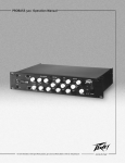
Occupational and Health Administration (OSHA) has specified the following permissible noise level exposures:
Duration Per Day In Hours
8
6
4
3
2
1 1/2
1
1/2
1/4 or less
Sound Level dBA, Slow Response
90
92
95
97
100
102
105
110
115
According to OSHA, any exposure in excess of the above permissible limits could result in some hearing loss. Ear plugs or protectors to the ear
canals or over the ears must be worn when operating this amplification system in order to prevent a permanent hearing loss, if exposure is in excess
of the limits as set forth above. To ensure against potentially dangerous exposure to high sound pressure levels, it is recommended that all persons
exposed to equipment capable of producing high sound pressure levels such as this amplification system be protected by hearing protectors while
this unit is in operation.
SAVE THESE INSTRUCTIONS!
Features and specifications subject to change without notice.
Peavey Electronics Corporation • 711 A Street • Meridian • MS • 39301
(601) 483-5365 • FAX (601) 486-1278 • www.peavey.com
©2000
80304743
Printed in the U.S.A. 9/00