Download PB Heat EC Series User's Manual

Transcript
Series EC/ECT
Oil Boilers
®
As an ENERGY STAR Partner, PB Heat, LLC has determined that certain firing
®
rates of this product meet the ENERGY STAR guidelines for energy efficiency.
Installation,
Operation &
Maintenance
Manual
TABLE OF CONTENTS
TABLE OF CONTENTS
USING THIS MANUAL
1
A. INSTALLATION CLEARANCE . . . . . . . . . . . . .1
B. SPECIAL ATTENTION BOXES . . . . . . . . . . . .1
1. PREINSTALLATION
2
A. CLEARANCES . . . . . . . . . . . . . . . . . . . . . . . .2
B. AIR FOR COMBUSTION AND
VENTILATION . . . . . . . . . . . . . . . . . . . . . . . . .2
C. CHIMNEY / VENT AND DRAFT CONTROL . .3
D. INSTALLATION SURVEY . . . . . . . . . . . . . . . .3
E. PLANNING THE LAYOUT . . . . . . . . . . . . . . . .3
2. BOILER PLACEMENT AND ASSEMBLY 4
A. SETTING THE BOILER . . . . . . . . . . . . . . . . . .4
B. OBSERVATION COVER ASSEMBLY
(KNOCKDOWN BOILERS) . . . . . . . . . . . . . . .4
C. INSTALLATION OF FLUE COLLECTORS &
COVERPLATES (KNOCKDOWN BOILERS) . .4
D. TANKLESS HEATER OR COVERPLATE . . . . .4
E. JACKET ASSEMBLY . . . . . . . . . . . . . . . . . . .4
3. PIPING AND CONTROLS
6
A. PRESSURE TEST BLOCK ASSEMBLY . . . . .6
B. BOILER RETURN CLEARANCE . . . . . . . . . . .6
C. STEAM BOILER PIPING . . . . . . . . . . . . . . . . .6
D. WATER BOILER PIPING . . . . . . . . . . . . . . . . .7
E. TANKLESS HEATER OR COVERPLATE . . . . .8
F. CONTROLS . . . . . . . . . . . . . . . . . . . . . . . . . . .9
4. ELECTRICAL
10
A. GENERAL . . . . . . . . . . . . . . . . . . . . . . . . . . .10
B. BURNER WIRING . . . . . . . . . . . . . . . . . . . . .10
5. BURNER SETUP & BOILER
OPERATION
14
A. BURNER INSTALLATION . . . . . . . . . . . . . . .14
B. BURNER START-UP AND ADJUSTMENT . .14
C. CHECK THE BOILER CONTROLS . . . . . . . .14
D. PURGE AIR FROM THE SYSTEM
(WATER BOILERS ONLY) . . . . . . . . . . . . . . .14
E. CLEAN THE BOILER
(STEAM BOILERS ONLY) . . . . . . . . . . . . . . .15
6. MAINTENANCE
17
A. GENERAL . . . . . . . . . . . . . . . . . . . . . . . . . . .18
B. DAILY MAINTENANCE (WITH BOILER
OPERATING) . . . . . . . . . . . . . . . . . . . . . . . . .18
C. WEEKLY MAINTENANCE (WITH BOILER
OPERATING) . . . . . . . . . . . . . . . . . . . . . . . . .18
D. MAINTENANCE OF SAFETY
RELIEF VALVE . . . . . . . . . . . . . . . . . . . . . . .18
E. MONTHLY MAINTENANCE (WITH BOILER
OPERATING) . . . . . . . . . . . . . . . . . . . . . . . . .18
F. MAINTENANCE – ANNUAL . . . . . . . . . . . . .18
G. IF A LONG SHUTDOWN IS REQUIRED . . .19
7. BOILER DIMENSIONS & RATINGS
20
8. REPAIR PARTS
22
USING THIS MANUAL
USING THIS MANUAL
A. INSTALLATION CLEARANCE
Follow the installation instructions provided in this
manual in the order shown. The order of these
instructions has been set in order to provide the installer
with a logical sequence of steps that will minimize
potential interferences and maximize safety during boiler
installation.
DANGER
Indicates a condition or hazard which
will cause severe personal injury,
death or major property damage.
WARNING
Indicates a condition or hazard which
may cause severe personal injury,
death or major property damage.
CAUTION
Indicates a condition or hazard which
will cause minor personal injury or
property damage.
NOTICE
Indicates special attention is needed,
but not directly related to potential
injury or property damage.
B. SPECIAL ATTENTION BOXES
Throughout this manual you will see special attention
boxes intended to supplement the instructions and make
special notice of potential hazards. These categories
mean, in the judgment of PB Heat, LLC.
1
PREINSTALLATION
1. PREINSTALLATION
Read carefully, study these instructions before beginning work. It will save time. Study the included drawings. Save these
instructions for reference.
This boiler must be installed by a qualified contractor.
The boiler warranty can be voided if the boiler is not installed, maintained and serviced correctly.
The equipment shall be installed in accordance with those installation regulations in force in the
local area where the installation is to be made, including the current edition of NFPA-31, Standard
for the Installation of Oil-Burning Equipment, and in Canada, CSA B139, Installation Code for Oil
Burner Equipment. These shall be carefully followed in all cases. Authorities having jurisdiction
shall be consulted before installations are made.
NOTICE
CAUTION
Never burn garbage or paper in the
unit, and never leave combustible
material around it.
CAUTION
Do not tamper with boiler controls.
A. CLEARANCES
Table 1.1: Clearances from Jacket and Vent System
Required from Jacket
to Combustible
Construction
Recommended From Jacket for
Accessibility and Mounting Controls
Top
5"*
24" if Left Side Clearance less than 24"
(to clean flueways from top).
Front
16"*
16" from jacket due to burner.
24" if Top Clearance less than 24"
(to clean flueways from left side).
Left
2"*
24" on steam with tankless coil.
9" in area of boiler service switch and
junction box.
Right
2"*
12" due to burner swing radius*.
Rear
2"*
9" for mounting relief valve.
Vent Pipe (Single Wall) - 9" to Combustible Construction.
Clearance may be reduced using methods in NFPA 31.
Vent Pipe (Double Wall) - See Manufacturer’s Instructions.
* Consider also vent pipe clearance, including distance from edge of
flue outlet to combustible construction (as applicable).
Unit may be installed on combustible flooring, provided the
boiler is not set on carpet and a metal drip pan is placed
under the appliance.
Unit may be installed in a closet with the above clearances.
See also Section B, Air for Combustion and Ventilation.
2
B. AIR FOR COMBUSTION AND
VENTILATION
1. Be certain adequate facilities are available to provide
air for satisfactory combustion and ventilation.
2. Appliances Located in Unconfined Spaces.
a. For installation in unconfined spaces with
conventional construction and larger areas such
as basements, the supply of air for combustion
and ventilation can usually be considered
adequate.
3. Appliances Located in Confined Spaces.
a. All air from inside the building: Provide two
permanent openings communicating directly with
an additional room. If all air for combustion and
ventilation is to come from within the building:
two openings, one near the ceiling and one near
the floor of the boiler room shall be provided
with the minimum free area of each opening
equal to 140 sq. in. per gallon of oil burned.
b. If all air for combustion and ventilation is to
come from outside the building: two openings,
one near the ceiling and one near the floor of the
boiler room shall be provided with the minimum
free area of each opening equal to 35 sq. in. per
gallon of oil burned.
If ducts are used to convey the air, areas of 35
sq. in. per gallon of oil burned for vertical ducts
or 70 sq. in. per gallon of oil burned for
horizontal ducts are to be provided. Ducts shall
have the same area as the free area of the
openings to which they are connected.
PREINSTALLATION
C. CHIMNEY / VENT AND DRAFT CONTROL
CAUTION
An oil-fired unit shall be connected
to a flue having sufficient draft at all
times, to assure safe proper
operation of the unit.
1. Draft Requirement – Minimum draft required in the
vent system is -.03" to -.05" W.C. depending on
boiler model, see Table 7.1 (Section 7). This draft is
necessary to provide the necessary draft over fire of
-.01" to -.02" W.C. See discussion in paragraph 5
below regarding draft.
2. Use barometric provided to control draft. Follow
manufacturer's instructions to locate and adjust the
control.
3. Inspect the existing chimney or vent system. Make
sure it is in good condition. Inspect chimney liner
and repair or replace if necessary.
4. The vent system and installation must be in
accordance with the current edition of the American
National Standard ANSI/NFPA 211, "Chimneys,
Fireplaces, Vents, and Solid Fuel Burning
Appliances," or applicable provisions of the local
building codes. See Table 7.1 (Section 7) for typical
chimney size. If the vent system is not sized properly,
the burner may not operate properly. This can cause
poor combustion, sooting and odors to occur.
5. Background Information Regarding Draft:
Modern boilers operate with higher efficiencies than
older boilers. Smaller flueways, as well as bars, pins
and fins are designed into modern boilers to transfer
as much heat as possible from the hot gases to the
water or steam and prevent heat loss up the
chimney. However, these design features result in
higher pressure, or draft loss, in the boiler.
This draft loss must be taken into account when
installing an oil boiler into a new or old chimney.
New chimneys are less likely to have poor draft.
However, they must have sufficient draft to support
combustion. A -.06" draft is desirable and preferred.
Older chimneys may require a replacement liner to
have them perform well enough to support
combustion.
For Example:
Old
New
Installation Installation
Comments
Chimney
Draft
-.04"
-.04"
No change, but older
chimneys (especially unlined
ones) have leaks which
reduce draft.
Boiler
Design
Pressure
Drop
+.01"
+.04"
Required for mandated
efficiency increases.
0.00"
The old installation would
have had a higher
temperature in the chimney
[as high as 800 degrees vs.
400 degrees F], which would
increase the draft.
Draft
Over Fire
-.03"
The above readings are "cold" readings (before the
boiler and chimney are heated up).
Note also that the higher the firing rate on a unit
which has multiple firing rates, the higher the draft
required. For example, increasing the firing rate 1/4
gallon may increase the draft loss in a unit by
approximately +.01".
D. INSTALLATION SURVEY
For new and existing installations, a Water Installation
Survey or a Steam Installation Survey is available from
P.B. Heat, LLC. The surveys will provide information on
how the boiler works with your specific system and will
provide an overview of boiler system operation in
general.
You can also use this survey to locate system problems
which will have to be corrected. To obtain copies of
these Surveys, contact your PB Heat representative or
download it from PeerlessBoilers.com.
E. PLANNING THE LAYOUT
Prepare sketches and notes of the layout of the
installation. Include boiler location, venting system,
existing piping and wiring. Show existing equipment that
may interfere with installation of new equipment.
3
BOILER PLACEMENT AND ASSEMBLY
2. BOILER PLACEMENT AND ASSEMBLY
A. SETTING THE BOILER
1. Provide a level foundation, located as close as
possible to the center of the heating system.
NOTICE
Be sure rubber gasket is in place
between cover plate or water heater
plate and boiler section.
E. JACKET ASSEMBLY
2. Refer to Figure 2.2 for exploded view of boiler while
checking and/or assembling parts of the boiler.
3. See clearance information in Section 1,
"Preinstallation."
4. On packaged boilers, open burner mounting plate
(Item 3) at this time to make certain the target wall
(Item 2) is seated in the back of the combustion
chamber. Ceramic fiber blanket base liner (Item 28)
should be lying flat on bottom of combustion
chamber between target wall and burner.
B. OBSERVATION COVER ASSEMBLY
(KNOCKDOWN BOILERS)
1. Remove observation door (Item 4) from inside
burner mounting plate. Attach the observation door
to the outside of the mounting plate.
C. INSTALLATION OF FLUE COLLECTOR &
COVERPLATES (KNOCKDOWN BOILERS)
1. Open flue collector carton. Remove flue collector
(Item 9) and high temperature rope. Lay rope (Item
8) on top of boiler against bead provided. Place flue
collector on top of rope and attach to boiler with
1/4"-20 x 1-3/4" studs with nuts through flue
collector brackets into the tapped lugs provided in
the top of the boiler end sections. Draw nuts down
snugly.
2. Remove clean-out cover plates and insulation (Item
25). Each clean-out cover plate is attached to the
boiler by using two carriage bolts, nuts and washers
(Item 24). Install the carriage bolts into the notch at
the top and bottom of each clean-out opening, then
secure them with a flat washer and steel nut as
shown in Figure 2.1 locking them in place. Press the
clean-out plate with insulation over the protruding
carriage bolts until the bolts punch through the
insulation so flat washer and brass nut can be
installed. Tighten down nuts snugly compressing the
insulation to form a good seal around the clean-out
opening.
D. TANKLESS HEATER OR COVERPLATE
If an ECT steam boiler is to be installed with a tankless
heater coil, the coil must be installed before the left side
jacket panels are attached. When a tankless heater is
not employed, cover the heater opening with cover plate
(Item 12 or 16).
See Section 3, Piping and Controls, for piping
information.
4
1. Refer to Figure 2.2 for exploded view.
2. Attach the back panel (Item 19) to bosses on middle
of back section with two 1/4" x 3/8" truss head
machine screws (Item 20) provided. The back panel
has two 5/16" diameter holes close to the center of
the panel.
3. Lift off the burner mounting plate.
4. Remove the (2) knock-outs in the front jacket panel
(Item 23) which allow clearance for the hinge. Place
the front jacket panel on the block and replace the
burner mounting plate.
5. Attach right side jacket panel (Item 22) to the front
and back panels with sheet metal screws.
6. On steam boilers, if a tankless heater is used, remove
the knock out in upper left side jacket panel (Item
21) and back jacket panel (Item 19) before installing.
Attach left side jacket panels in the same manner as
the right side panel.
7. Attach the top panel (Item 26). Secure top panel to
front and back panel with sheet metal screws.
Figure 2.1: Side Clean-out Cover Plates
BOILER PLACEMENT AND ASSEMBLY
Figure 2.2: Boiler Exploded View
(See Table 8.1 in Section 8 for parts identification).
5
PIPING AND CONTROLS
3. PIPING AND CONTROLS
NOTICE
Do not pipe boiler before jacket is
installed.
EQUALIZER
A. PRESSURE TEST BLOCK ASSEMBLY
1. Make up cold water supply connection to the boiler.
2. Install pressure gauge or pressure-temperature gauge
in tapping provided. See Boiler Dimensional
drawing, Figure 7.1 (Section 7).
3. Plug all open tappings in the boiler and fill with
water. Apply approximately thirty (30) psig pressure.
Check to make certain that all joints and fittings are
water tight.
4. After all joints and connections have been proven
tight, remove cold water supply and plugs from
all tappings that are to be used. See Figure 7.1
(Section 7) for tapping locations.
B. BOILER RETURN CLEARANCE
Return piping must allow for opening and closing
Burner Mounting Plate. PB Heat, LLC suggests installing
a 1-1/4 NPT tee, a 90° elbow, and a 1-1/4 NPT x 5"
long nipple in the return tapping before a vertical stand
pipe is used.
FRONT
REAR
Figure 3.1: Steam Boiler Piping, EC-03
HEADER
EQUALIZER
RISERS
FRONT
REAR
Figure 3.2: Steam Piping, EC-04 to EC-06
C. STEAM BOILER PIPING
1. Refer to the Steam Installation Survey and
Hydronics Institute Residential Hydronic Heating
Installation/Design Guide for guidance.
2. See Figures 3.1 and 3.2. The return from system
should always enter equalizer through Hartford
Loop, 2" to 4" below normal water line (see
dimensional drawing for normal water line).
3. See Table 3.1 for pipe size information.
4. Use swing joints to attach header to avoid damage
to the boiler due to thermal expansion and
contraction of steam header pipe.
5. Pipe the steam header a minimum of 24" above the
normal water line using swing joints to attach the
risers into the steam header.
6
Table 3.1: Steam Pipe Sizing
Boiler Model No.
Risers
EC/ECT-03-075
EC/ECT-03-100
EC/ECT-03-120
EC/ECT-04-125
EC/ECT-04-175
EC/ECT-04-175
EC/ECT-05-200
EC/ECT-05-250
EC/ECT-06-275
EC/ECT-06-300
1-2"
1-2"
1-2"
2-2"
2-2"
2-2"
2-2"
2-2"
2-2"
2-2"
Header
Equalizer
2-1/2"
2-1/2"
2-1/2"
3"
3"
3"
3
1-1/4"
1-1/4"
1-1/4"
1-1/2"
1-1/2"
1-1/2"
1-1/2"
1-1/2"
1-1/2"
1-1/2"
PIPING AND CONTROLS
D. WATER BOILER PIPING
1. Refer to the Water Installation Survey and Hydronics
Institute Residential Hydronic Heating
Installation/Design Guide for Guidance.
2. The supply and return connections should be sized
to suit the system.
3. Pipe the supply and return in one of two ways as
shown in Figure 3.3:
a. Pipe the supply from the top of the rear section
and return to the bottom of the front section. Use
the 3/4" tapping in the top of the back section for
air elimination.
b. As an alternative, pipe the supply from the top of
the front section and return to the bottom of the
rear section. Provide air elimination means
within the supply piping.
Figure 3.3: Water Boiler Piping
4. When the return temperature from the system will be
below 150°F on oil boilers for extended periods
(heat pump systems, outdoor reset, snow melt, etc.),
provide piping and controls to protect the boiler from
condensation. Condensation will damage the boiler
and will lead to shortened boiler life and
maintenance problems.
5. If using a Partner indirect fired water heater or other,
see Figure 3.4 for typical piping. Also refer to
additional instructions supplied with the Partner.
6. If the boiler is to be used in conjunction with a
refrigeration system, the chilled medium shall be
piped in parallel with boiler and proper valves
applied to prevent the chilled medium from entering
the boiler. Refer to Figure 3.5.
7. If the boiler is connected to heating coils located in
air handling units, the boiler piping system must be
equipped with flow control valves or other automatic
devices to prevent gravity circulation of the boiler
water during the cooling cycle.
Figure 3.4: Piping with Peerless Indirect
Water Tank
Figure 3.5: Isolating Boiler from Chilled Medium
on Chiller Systems
7
PIPING AND CONTROLS
E. TANKLESS HEATER OR COVERPLATE
1. If a tankless coil is used (item 13 or 17), install as
pictured. On water boilers, install in opening in front
section. On steam boilers, install in opening in rear
section. For suggested piping of tankless water
heaters refer to Figures 3.6 and 3.7.
2. If not using a tankless coil, cover the heater opening
with cover plate (item 12 or 16).
NOTICE
Be sure rubber gasket is in place
between cover plate or water heater
plate and boiler section.
3. See Table 3.2 for tankless coil ratings.
DANGER
Install anti-scald device in hot water
supply piping. Water temperature
above 125°F can cause severe burns
instantly or death from scalds.
Table 3.2: Maximum Tankless Water
Heater Ratings
Heater No.
NOTICE
X1020R and X1082R coils installed in
EC/ECT-03 & 04 packaged boilers
have internal flow controls installed.
Do not use external flow controls
with these coils.
Figure 3.6: Tankless Coil Piping, Water Boiler
8
X1020
X1020R
X1082
X1082R
Capacity*
GPM
Boiler Series
5
Series EC
4
Series ECT
* Water Heater ratings are based on intermittent demand -40°F to
140°F with 200°F Boiler Water.
Figure 3.7: Tankless Coil Piping, Steam Boiler
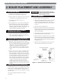
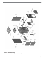
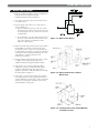
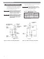
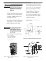
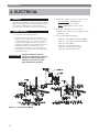
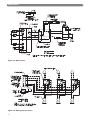
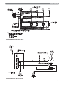
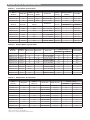
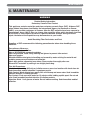
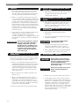
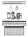
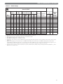
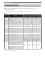
PIPING AND CONTROLS
F.
CONTROLS
CAUTION
Pipe the discharge of the safety
valve or relief valve to prevent injury
in the event of pressure relief. Pipe
the discharge to a drain. Provide
piping that is the same size as the
relief valve.
1. Water Boiler Controls:
Install the limit / operating control, pressuretemperature gauge and safety relief valve. See Figure
7.1 (Section 7) for proper location. For installations
subject to UL726, a second operating control that
senses water temperature is also required (not
provided). Use an L4080B or equivalent. Install in
the supply piping near the boiler.
2. Steam Boiler with Float Low Water Cut-Off:
Install pressure limit control, pressure gauge, gauge glass
trim and safety valve. See Figure 3.8, Figure 3.9, and
Figure 7.1 (Section 7). See also control manufacturer's
instruction sheet shipped with the control.
Use these components along with the gauge glass
handles and other components from the Steam Trim
Carton and install fittings and controls per Figure 3.10.
The shorter gauge glass located in the Steam Trim
Carton is not necessary for the probe application.
4. Steam boilers subject to UL726:
For installations subject to UL726, a second
operating control that senses steam pressure is
required (not provided). Use a PA404A or
equivalent. On probe boilers, install the additional
pressure control opposite the standard PA404A using
a cross instead of a tee along with a second brass
siphon (not provided). On float boilers, install the
additional pressure control in the location normally
used for the standard PA404A on steam-probe
boilers (fittings not provided).
5. For complete information on servicing and
adjustment of controls, refer to the attached control
specification sheets.
3. Steam boilers with Probe Low Water Cut-Off:
CAUTION
Use only the Hydrolevel CG450 as
a primary probe low water. The
CG450 includes a cycle timer to
sense water level under foaming or
surging conditions. Failure to use
this model could result in a failed
heat exchanger.
Probe models use a longer gauge glass than float
models. The following components are packed in the
Probe Carton (90759):
Hydrolevel CG450 LWCO
·
· Gauge glass 22-162-10
· 3/4"x 3" nipple
· 3/4" x 3/4" x 1/4" tee
· (2) 1/2" couplings
Figure 3.8: Steam Boiler with Float Low
Water Cut-Off
Figure 3.9: Assembling Float Low Water Cut-Off
Figure 3.10: Steam Boiler with Probe Low
Water Cut-Off
9
ELECTRICAL
4. ELECTRICAL
3. Install burner harness located in the burner carton.
A. GENERAL
All electrical wiring shall be done in accordance with the
National Electrical Code and Local Requirements. Single
pole switches including those of safety controls or
protective devices shall not be wired in a grounded line.
B. BURNER WIRING
Beckett or Carlin – EC7022 Harness
(21" conduit)
Riello – EC7023 Harness (28" conduit)
4. For complete information on servicing and
adjustment of controls, refer to the attached control
specification sheets.
1. See Section 5 for mounting burner.
5. See the following Wiring Diagrams:
2
Install junction box, limit harness, and Heyco
bushing, each located in the trim carton. See Figure
4.1. Mount junction box to the holes in the left side
of jacket with (2) #10 x 1/2" sheet metal screws.
Attach Heyco bushing to 7/8" knockout in front side
of junction box. Connect limit harness to 7/8"
knockout on top of junction box and insert limit
harness Molex connector into Heyco bushing until it
snaps firmly in place.
WARNING
Improper installation of burner
harness can allow burner to energize
with burner mounting plate open,
creating a severe burn hazard to
boiler maintenance personnel.
Figure 4.1: Junction Box Wiring
10
Figure
Figure
Figure
Figure
Figure
Figure
4.2
4.3
4.4
4.5
4.6
4.7
-
Steam Boilers with Float LWCO
Steam Boilers with Probe LWCO
Water Boilers
Zoning with Circulators
Zoning with Zone Valves
Partner with Circulator
ELECTRICAL
Figure 4.2: Steam Boiler with Float Low Water Cut-Off
Figure 4.3: Steam Boiler with Probe Low Water Cut-Off
11
ELECTRICAL
Figure 4.4: Water Boilers
Figure 4.5: Zoning with Circulators
12
ELECTRICAL
Figure 4.6: Zoning with Zone Valves
Figure 4.7: Partner with Circulator
13
BURNER SETUP & BOILER OPERATION
5. BURNER SETUP & BOILER OPERATION
CAUTION
Burn only #2 Fuel Oil in this
appliance. Do not use gasoline,
crankcase drainings or any oil
containing gasoline.
A. BURNER INSTALLATION
1. The oil burner is supplied with a mounting flange
fixed in position.
2. Mount the burner to the Burner Mounting Plate
(item 3) with four (4) 5/16" studs and nuts provided.
NOTICE
Be sure hi temp gasket is between
the burner mounting flange and the
Burner Mounting Plate.
3. Care must be taken when routing the oil lines so not
to interfere with the opening and closing of the
burner mounting plate. Flexible oil lines or flared
copper disconnects with valves (when copper lines
are used) may be installed to assure full opening of
the burner mounting plate when servicing.
2. Adjust burner and barometric draft control for
highest CO² (Maximum 13% [EC-03 - EC-05] or
12-1/2% [EC-06]) while maintaining a 0 Smoke and
-.01 to -.02" W.C. draft overfire.
All adjustments must be made using suitable
instruments such as found in a Bacharach
Combustion Test Kit.
3. Burner and boiler can be shut down by turning
down the thermostat and moving the main boiler
service switch to the "off" position.
4. See burner manufacturer's manual for further
information regarding the burner.
C. CHECK BOILER CONTROLS
1. Limit and Operating Controls:
a. Lower the set point of each control until the
burner shuts down. Note that the system pressure
(or temperature) corresponds to the desired set
point.
b. Return the controls to the desired set point.
NOTICE
Two-pipe oil supply for Riello burner
requires a separate kit. Order part
#C7001026 from Riello dealer.
4. Oil burner specifications:
For information pertinent to the oil burner such as
nozzle sizing, fuel supply piping, adjusting or
servicing, refer to the charts in this section and the
burner installation manual.
B. BURNER START-UP AND ADJUSTMENT
CAUTION
Do not start the burner unless all
cleanout doors are in place.
1. Burner should start automatically when thermostat is
turned up and main boiler service switch is turned
on. If burner does not start, check to be sure there is
oil in the tank and push reset button on burner
control:
Beckett: Square red button.
Carlin: Round red button.
Riello: Round red button inside clear flexible
cover on back of burner cover.
If burner still does not start, contact serviceman.
CAUTION
14
Do not attempt to start the burner
when excess oil has accumulated,
when the unit is full of vapor, or
when the combustion chamber is
very hot.
2. Low Water Cut-off (if used) - consult the
manufacturer's instructions for the low water cut-off
operational check procedure.
D. PURGE AIR FROM THE SYSTEM
(WATER BOILERS ONLY)
1. Purge the system using purge valves, isolating zones
in the process or use system vents. Do not operate
the pump(s) while purging. Pumps will hold air in
the eye of the impeller.
2. Allow the system to reach 180°F and use manual
vents, if installed, to remove any remaining air.
Watch the pressure gauge as the system approaches
180°F. If the pressure exceeds the design operating
pressure, check:
a. Fill valve pressure.
b. Expansion or compression tank operation and
sizing.
BURNER SETUP & BOILER OPERATION
E. CLEAN THE BOILER
(STEAM BOILERS ONLY)
1. Clean the boiler within one week after initial start-up.
Cleaning will be more effective if boiler operates a
day or two to loosen sediment and impurities in
system.
2. Boiler must be cleaned to remove any accumulation
of oil, grease, sludge, etc. in the system. These
substances can cause foaming and surging of boiler
water, producing an unstable water line and water
carryover to system.
WARNING
Cleaning the boiler requires the use
of very hot water and corrosive
chemicals. Use care when handling
to prevent injury.
3. Connect a skim valve off the 1-1/2 NPT skim tapping
on rear of boiler. See Figure 7.1 (Section 7) for skim
tapping location. Run a 1-1/2 NPT drain line off
skim valve to a point of safe discharge.
4. Provide a means of supplying continuous fresh water
to the boiler for the cleaning process.
5. Use common washing soda, such as Arm and
Hammer Super Washing Soda. Mix 1/2 pound of
soda with water in a 10 quart pail. Pour the mixture
into the boiler through the safety relief valve tapping.
6. Open the skim valve. Fill boiler until water begins to
flow out of the valve.
CAUTION
Do not leave boiler unattended while
firing burner. Operating boiler with
water below minimum permissible
water level may fracture sections.
7. Turn on burner. Allow boiler water to heat up to just
below steaming (180 - 200°F). Do not allow boiler to
steam; steaming mixes up contaminants instead of
floating them at surface.
8. Open make-up water valve to continually feed water
to boiler. Adjust flow to maintain water temperature
at 180 - 200°F.
CAUTION
Do not allow make-up water to flow
too fast. Excessive quantities of cold
water may fracture sections.
9. Continue skimming boiler until water flowing from
skim tapping flows clear. This will take some time,
possibly several hours for a dirty system.
10. Turn off burner, close make-up water valve.
11. Drain boiler completely. Refill and drain one or two
times to wash out all washing soda.
12. Remove skim valve and piping. Pipe a nipple and
cap in the skim valve.
NOTICE
If gauge glass becomes dirty more
contaminants have worked loose in
system. Repeat cleaning and
skimming process as needed to
clean system.
15
BURNER SETUP & BOILER OPERATION
Table 5.1: Carlin Burner Specifications
CARLIN BURNER SPECIFICATIONS
Boiler
Model No.
Firing Rate
Burner
Model No.
Air
Shutter
Nozzle Size
Pump
Pressure
Start-up Settings
Air Band
Head Bar
EC/ECT-03-075
.75
EZ-1HP
Blank
0.60 70° B DEL³
150 psig
0.55
0.60 - 0.65
EC/ECT-03-100
1.00
EZ-1HP
Blank
0.85 70° A DEL
150 psig
0.65
0.85 - 1.00
EC/ECT-03-120
1.20
EZ-1HP
Blank
1.00 70° A DEL³
150 psig
0.80
0.85 - 1.00
Start-up Settings
Boiler
Model No.
Burner
Model No.
Air
Shutter
Nozzle Size
Pump
Pressure
Head Dim. A
Air Band
EC/ECT-04-125
99FRD
Blank
1.00 x 70° B DEL³
150 psig
2
40% open
EC/ECT-04-150
99FRD
Blank
1.25 x 60° B DEL³
150 psig
3
60% open
EC/ECT-04-175
99FRD
Blank
1.50 x 60° B DEL
150 psig
4
100% open
EC/ECT-05-175
99FRD
Open
1.50 x 60° B HAGO³
150 psig
5
10% open
EC/ECT-05-200
99FRD
Open
1.65 x 60° B HAGO
150 psig
5
45% open
EC/ECT-05-250
99FRD
Open
2.00 x 60° B HAGO³
150 psig
8
100% open
EC/ECT-06-275
102CRD
Open
2.25 x 60° B DEL³
150 psig
6
100% open
EC/ECT-06-300
102CRD
Open
2.50 x 60° B DEL
150 psig
8
100% open
Table 5.2: Beckett Burner Specifications
BECKETT BURNER SPECIFICATIONS (140 psig Pump Pressure)
Boiler
Model No.
Burner
Model No.
Burner Head
Static Plate
EC/ECT-03-075
AFG-L1¹
L1¹
3-3/8"
EC/ECT-03-100
AFG-L1
L1
3-3/8"
EC/ECT-03-120
AFG-L1
L1
—²
EC/ECT-04-125
AFG-F6
F6
EC/ECT-04-150
AFG-F6
EC/ECT-04-175
AFG-F6
EC/ECT-05-175
Start-up Settings
Nozzle Size
Head Setting
Air Shutter
Air Band
0.65 60° B HAGO³
9.0
2
N/A
0.85 60° B HAGO
10.0
1
N/A
1.00 60° B HAGO³
9.0
2
N/A
2-3/4"
1.10 80° A DEL³
5.0
1
N/A
F6
2-3/4"
1.25 80° B HAGO
8.0
1
N/A
F6
2-3/4"
1.50 80° B HAGO³
10.0
3
N/A
AFG-MV1
M-V1-3
—
1.50 60° B HAGO³
10.0
3
3
EC/ECT-05-200
AFG-MV1
M-V1-3
—
1.75 60° B HAGO
10.0
9
3
EC/ECT-05-250
AFG-MV1
M-V1-5
—
2.00 45° B HAGO³
10.0
5
5
EC/ECT-06-275
CF-375
L1-S
—
2.25 45° P HAGO³
10.0
6
2
EC/ECT-06-300
CF-375
L1-S
—
2.50 45° P HAGO
10.0
6
3
Table 5.3: Riello Burner Specifications
RIELLO BURNER SPECIFICATIONS
Boiler
Model No.
Firing Rate
Burner
Model No.
Nozzle Size
Pump Pressure
EC/ECT-03-075
.75
F5
0.60 60° B DEL³
EC/ECT-03-100
1.00
F5
EC/ECT-03-120
1.20
EC/ECT-04-125
1.25
EC/ECT-04-150
Start-Up Settings
Turbulator
Air Damper
155 psig
0.5
2.1
0.85 60° W DEL³
145 psig
2.0
2.6
F5
1.00 60° W DEL
145 psig
3.0
2.9
F5
1.00 60° W DEL
155 psig
2.5
3.4
1.50
F10
1.25 60° B DEL³
145 psig
1.5
3.1
EC/ECT-04-175
1.75
F10
1.35 60° B DEL
165 psig
2.0
2.5
EC/ECT-05-175
1.75
F10
1.35 60° B DEL³
165 psig
2.0
2.5
EC/ECT-05-200
2.00
F10
1.50 60° B DEL
170 psig
2.5
2.8
EC/ECT-05-250
2.50
F10
2.00 60° B DEL³
155 psig
3.5
4.2
EC/ECT-06-275
2.75
F10
2.25 60° B DEL³
150 psig
4.0
4.2
EC/ECT-06-300
3.00
F10
2.50 60°B DEL
145 psig
4.5
4.2
Factory Installed Nozzles (Packaged Boilers or Burner Cartons) are indicated in Boldface.
1 Requires Low Firing Rate Baffle
2 Remove Static Plate for 1.20 GPH Rate
3 Shipped Loose with Packaged Boiler or Burner Carton
16
MAINTENANCE
6. MAINTENANCE
WARNING
Product Safety Information
Refractory Ceramic Fiber Product
This appliance contains materials made from refractory ceramic fibers (RCF). Airborne RCF,
when inhaled, have been classified by the International Agency for Research on Cancer
(IARC), as a possible carcinogen to humans. After the RCF materials have been exposed to
temperatures above 1800°F, they can change into crystalline silica, which has been classified
by the IARC as carcinogenic to humans. If particles become airborne during service or
repair, inhalation of these particles may be hazardous to your health.
Avoid Breathing Fiber Particulates and Dust
Suppliers of RCF recommend the following precautions be taken when handling these
materials:
Precautionary Measures:
Provide adequate ventilation.
Wear a NIOSH/MSHA approved respirator.
Wear long sleeved, loose fitting clothing and gloves to prevent skin contact.
Wear eye goggles.
Minimize airborne dust prior to handling and removal by water misting the material and
avoiding unnecessary disturbance of materials.
Wash work clothes separately from others. Rinse washer thoroughly after use.
Discard RCF materials by sealing in an airtight plastic bag.
First Aid Procedures:
Inhalation: If breathing difficulty or irritation occurs, move to a location with fresh clean air.
Seek immediate medical attention if symptoms persist.
Skin Contact: Wash affected area gently with a mild soap and warm water. Seek immediate
medical attention if irritation persists.
Eye Contact: Flush eyes with water for 15 minutes while holding eyelids apart. Do not rub
eyes. Seek immediate medical attention if irritation persists.
Ingestion: Drink 1 to 2 glasses of water. Do not induce vomiting. Seek immediate medical
attention.
17
MAINTENANCE
A. GENERAL
1. Check pipes adjacent to cold walls or in unheated
spaces. Insulate and tape them if necessary to be
sure they can't freeze up. Keeping the water moving
at all times will reduce the likelihood of freezing.
2. If there is considerable foreign matter in the boiler
water, the boiler should be shut down and allowed to
cool, then drained and thoroughly flushed out. Drain
the boiler at the drain cock. Pipe the drain cock to a
suitable drain or containment device (if antifreeze is
used). Flush the system to remove remaining matter.
If there is evidence that hard scale has formed on the
internal surfaces, the boiler should be cleaned by
chemical means as prescribed by a qualified water
treatment specialist.
C. WEEKLY MAINTENANCE (WITH BOILER
OPERATING)
1. Flush float-type low-water cut-off (if used) to remove
sediment from the float bowl as stated in the
manufacturer's instructions.
D. MAINTENANCE OF SAFETY RELIEF
VALVE
1. Check function and maintain safety relief valve as
specified by manufacturer, typically every other
month or every month, per the instructions on the
tag on the safety relief valve.
E. MONTHLY MAINTENANCE (WITH BOILER
OPERATING)
3. There must be no signs of continuous wetness at the
chimney. If signs of continuous wetness are
observed, a qualified service agency must be
consulted to modify the vent configuration to prevent
the formation of condensate, which may damage the
vent pipe.
WARNING
Do not use this appliance if any part
has been under water. Improper or
dangerous operation may result.
Immediately call a qualified service
technician to inspect the boiler and
to replace any part of the control
system and any control which has
been under water.
B. DAILY MAINTENANCE (WITH BOILER
OPERATING)
Daily boiler observation can be performed by the owner.
If any potential problems are found, a qualified installer
or service technician/agency must be notified.
1. Remove any combustible materials, gasoline and
other flammable liquids and substances that generate
flammable vapors from the area where the boiler is
contained. Make certain that the boiler area has
ample air for combustion and ventilation and that
there are no obstructions to the free flow of air to
and from the boiler.
2. Observe general boiler conditions (unusual noises,
vibrations, etc.).
3. Observe operating temperature and/or pressure
gauge on the boiler. Boiler pressure should never be
higher than 5 psi below the rating shown on the
safety relief valve. The valve rating can be found on
the top of the safety relief valve. Boiler temperature
should never be higher than 250°F.
4. Check for water leaks in boiler and system piping.
18
1. Check boiler room floor drains for proper
functioning.
2. Test probe type low-water cut-off (if used) by using
the Push-to-Test Button.
CAUTION
Turn off power to boiler before
adjusting limit control.
3. Test limit by lowering the limit set point until the
burner shuts down. When proper operation is
confirmed, return the set point to original setting.
4. Follow additional instructions in the Burner Manual
for proving the burner component operation.
F.
MAINTENANCE – ANNUAL
NOTICE
WARNING
Entire heating system, including
boiler, burner and venting system,
must be inspected at least once a
year by a qualified heating
professional. Boiler is to be cleaned
at least once a year.
Disconnect all power to the burner
before accessing combustion
chamber.
TO CLEAN:
1. Remove top jacket panel and flue collector, Item 9.
2. To thoroughly clean the boiler it must be brushed
down from the top and/or left side. Alternatively, for
limited space or minimum clearance to combustible
installations, cleaning the heat exchanger from the
combustion chamber side is acceptable. If unit is
extremely dirty, it may be necessary to brush from all
directions. The target wall is made of a soft ceramic
fiber. Care must be taken not to damage this
material during cleaning.
MAINTENANCE
3. Remove any scale or soot from the combustion
chamber area by vacuum cleaning or any other
available means.
NOTICE
Burner mounting plate must be
opened to facilitate this operation.
4. Replace flue collector and close burner mounting
plate, making sure all gaskets are in place.
5. Replace jacket top panel.
NOTICE
All cover plates, enclosures, and
guards must be maintained in place
at all times, except during
maintenance and servicing.
G. IF A LONG SHUTDOWN IS REQUIRED
1. To take boiler out of service if the boiler and system
are not to be used when temperatures are below
freezing:
a. Drain the boiler and system completely and shut
off make-up water supply.
b. Open main line power disconnect switch to
boiler. Remove the fuses or secure the switch so
that the power cannot be turned on accidentally.
CAUTION
Always keep the manual fuel supply
valve shut off if the burner is shut
down for an extended period of time.
2. Be certain that the boiler and system are refilled
before returning to service.
6. Inspect venting system.
19
BOILER DIMENSIONS & RATINGS
7. BOILER DIMENSIONS & RATINGS
Figure 7.1: Boiler Dimensions / Purpose of Tappings
DIMENSIONS
Boiler
Model
Width
“A”
Jacket
Depth
“B”
Height
“C”
Length of
Fire Box
“D”
Rear of
Jacket to Flue
“E”
Flue Outlet
Diameter
“F”
Distance Between
Tappings
“G”
9-1/16"
EC/ECT-03
22-1/2"
15-3/4"
42"
10"
8-3/4"
6"
EC/ECT-04
22-1/2"
19-15/16"
42"
14-3/16"
10-7/8"
7"
13-1/4"
EC/ECT-05
22-1/2"
24-1/8"
42"
18-3/8"
13"
8"
17-7/16"
EC/ECT-06
22-1/2"
28-5/16"
42"
22-9/16"
15-1/16"
9"
21-5/8"
* Dimensions are approximate.
TAPPING LOCATIONS
20
Location
Size NPT
Water
Steam
H
I
3/4"
N/A
Low Limit Control
3/4"
Limit Control
Pressure Gauge
L
1/4"
Temperature-Pressure Gauge
Limit Control
M
1/2"
N/A
Gauge Glass and Low Water Cut-Off
N
2"
Optional Return
Return
O
3/4"
Secondary Probe Low Water Cut-Off
P
3/4"
Safety Relief Valve
Safety Valve
Q
1-1/4"
Return
N/A
R
3/4"
Drain Valve
Drain Valve
S
1-1/2"
Optional High Limit
Skim
T
3/4"
N/A
Primary Probe Low Water Cut-Off
U
1/2"
N/A
Gauge Glass w/ Probe LWCO
BOILER DIMENSIONS & RATINGS
Table 7.1: Boiler Ratings
Series EC/ECT
Water Content, Minimum
gal
Stack
Thermal Combustion
Draft
6
Steam, Steam, Water,
Efficiency , Efficiency,
Required,
Water Steam in. W.C.
GPH¹ MBH Water Steam sqft MBH³ MBH² Water Steam
%
%
Input
Model
Number
EC/ECT-03✸ 0.75
✸
105
Output5,
MBH
92
91
Net I=B=R Ratings4
283
68
80
AFUE,
%
86.6✸
85.4✸
–
–
17.40
14.16
-.03
84.4
–
–
17.40
14.16
-.04
EC/ECT-03
1.00
140
121
120
375
90
105
EC/ECT-03
144
142
446
107
125
83.9
82.9
–
–
17.40
14.16
-.05
113
132
86.1✸
85.1✸
–
–
21.72
17.28
-.03
85.2✸
84.5
–
–
21.72
17.28
-.04
1.20
168
EC/ECT-04✸ 1.25
175
152
151
471
EC/ECT-04✸ 1.50
210
181
180
563
135
157
EC/ECT-04
85.3
✸
1.75
245
209
208
650
156
182
84.5
83.8
–
–
21.72
17.28
-.05
EC/ECT-05✸ 1.75
245
214
212
663
159
186
86.2✸
85.6✸
–
–
26.04
20.40
-.03
EC/ECT-05✸ 2.00
280
241
240
750
180
210
85.2✸
84.6
–
–
26.04
20.40
-.04
2.50
350
286
286
896
215
249
–
–
81.9
84.1
26.04
20.40
-.05
EC/ECT-06✝ 2.75
385
321
321
1004
241
279
–
–
83.3
84.4
30.36
23.52
-.04
420
347
347
1083
261
302
–
–
82.5
83.7
30.36
23.52
-.05
✝
EC/ECT-05
✝
EC/ECT-06
3.00
✸
✝
1
2
3
4
As an ENERGY STAR® Partner, PB Heat has determined that these firing rates meet the ENERGY STAR guidelines for energy efficiency.
All chimneys are 8" x 8" x 20' except those models denoted with (✝), which are 8" x 12" x 20'.
Burner input based on No. 2 fuel oil with a heating value of 140,000 Btu per gallon.
Net I=B=R water ratings based on an allowance of 1.15.
Net I=B=R steam ratings based on an allowance of 1.333.
Consult factory before selecting a boiler for installations having unusual piping and pickup requirements, such as intermittent system operation, extensive piping
systems, etc.
5 Output is Heating Capacity for models with inputs <300 MBH and Gross Output for models with inputs ≥300 MBH. Heating Capacity and Annual Fuel
Utilization Efficiency (AFUE) ratings are based on U.S. Government tests, with 13% CO² and –0.02" w.c. draft over fire. Before purchasing this appliance, read
important information about its estimated annual energy consumption or energy efficiency rating that is available from your retailer.
6 Combustion efficiency and gross output are determined in accordance with The Hydronics Institute’s Testing and rating standard for Heating Boilers; @ 12.5%
CO² and -0.02" w.c. draft over fire.
21
REPAIR PARTS
8. REPAIR PARTS
Repair parts are available from your installer or by contacting PB Heat, LLC, 131 S.
Church, Bally, PA 19503.
Note: Remember to include boiler model number and serial number when ordering parts.
Table 8.1
Repair Part Stock Code
Item No.*
1
Description
EC/ECT-03
EC/ECT-04
EC/ECT-05
EC/ECT-06
Block Assembly - EC
90662
90663
90239
90758
Block Assembly - ECT
90664
90665
90242
90755
2
Target Wall
50768
3
Burner Mounting Plate
93530
4
Observation Door
51677
5
5-16" - 18 x 2-1/4" Stud (use with 5/16-18 Nut)
6
Burner Mounting Plate Internal Hinge
51149
8
High Temp. Rope 1/2" Diameter Medium Density
[48"]
51211
9
Flue Collector (EC05 & EC06 stock codes include side
cleanout plates)
90555
10
1/4"-20 x 1-3/4" Stud (use with 1/4-20 Nut)
11
Rubber Gasket
12
Cover Plate
13
Tankless Coil (Optional Water Only)
90534
14
3/8"-16 x 3/4" Hex Hd. Cap Screws
[6] 99788
15
Rubber Gasket (ECT Models)
16
Cover Plate (Optional ECT Models)
17
Tankless Heater (Optional ECT Models)
18
3/8"-16 x 3/4" Hex Hd. Cap Screws
24
5/16"-18 x 1-3/4" Carriage Bolt (use with 5/16-18 Nut)
[4] 93997
[6] 93997
[8] 93997
[10] 93997
25
Side Cleanout Cover Plate
[2] 51772
[3] 51772
[4] 51772
[5] 51772
28
Base Liner, 1/2" x 14"
50857 (6")
50858 (10-1/2")
19
Back Jacket Panel
20
[2] 1/4"-20 x 3/8" Truss Hd. Mach. Screw Zinc
21
Upper Left Side Jacket Panel
21A
Lower Left Side Jacket Panel
90278
(Jacket
Assembly)
90279
(Jacket
Assembly)
22
Right Side Jacket Panel
23
Front Jacket Panel
26
Top Jacket Panel
* See Figure 2.2 on page 5 for boiler exploded view.
22
[3] 51747
[56"]
51211
[64"]
51211
[72"]
51211
90556
99538
99539
[2] 51751
51800
99812 (includes gasket and cap screws)
90547
90140 (includes gasket and cap screws)
90546
[6] 99788
50846 (18-3/4" LG)
90280
(Jacket
Assembly)
90281
(Jacket
Assembly)
NOTES
23
NOTES
24
Series EC/ECT
Oil Boilers
Installation,
Operation &
Maintenance
Manual
TO T H E I N S TA L L E R :
This manual is the property of the owner and must
be affixed near the boiler for future reference.
TO T H E O W N E R :
This boiler should be inspected annually by a
Qualified Service Agency.
Service Information
Name:
Address:
PB HEAT, LLC
131 S. CHURCH ST • BALLY, PA 19503
Phone:
ASME
©2008
EC8000 R24 (2/08-5M)
Printed in U.S.A.