1
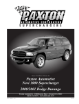
Owner’s Installation Guide for the
Paxton Automotive
Novi 1000 Supercharger
for the
2002 Dodge Ram 1500
Paxton Automotive . 1300 Beacon Place . Oxnard CA 93033
888 9-PAXTON . FAX (805) 604-1337
DP/N: 4809641a - Ram 1500 v1.1
05/01/06
FOREWORD
T
his manual provides information on the installation, maintenance and service of the
Paxton supercharger kit expressly designed for the 2002 4.7L Dodge Ram. Contact
Paxton Automotive Corporation for any additional information regarding this kit and
any of these modifications at (805) 604-1336 7:00am-3:30pm PST.
An understanding of the information contained herein will help novices, as well as experienced technicians, to correctly install and receive the greatest possible benefit from their
Paxton supercharger. When reference is made in this manual to a brand name, number, specific tool or technique, an equivalent product may be used in place of the item mentioned.
All information, illustrations and specifications contained herein are based on the latest
product information available at the time of this publication. All rights reserved to make
changes at any time without notice.
This is a typical underhood shot after installaton. Your engine compartment may look different.
© 2006 PAXTON AUTOMOTIVE
All rights reserved. No part of this publication may be reproduced, transmitted, transcrived, or translated into
another language in any form, by any means without written permission of Paxton Automotive.
P/N: 4809641a
©2006 Paxton Automotive
All Rights Reserved, Intl. Copr. Secured
01MAY06 v1.1 Dodge Ram 1500(4809641a v1.1)
ii
TABLE OF CONTENTS
FOREWORD . . . . . . . . . . . . . . . . . . . . . . . . . . . . . . . . . . . . . . . . . . . . . . . . . . . . . . . . . . . . . . . . . . . .ii
TABLE OF CONTENTS . . . . . . . . . . . . . . . . . . . . . . . . . . . . . . . . . . . . . . . . . . . . . . . . . . . . . . . . . . .iii
TOOL & SUPPLY REQUIREMENTS . . . . . . . . . . . . . . . . . . . . . . . . . . . . . . . . . . . . . . . . . . . . . . .iv
1.
INTRODUCTION . . . . . . . . . . . . . . . . . . . . . . . . . . . . . . . . . . . . . . . . . . . . . . . . . . . . .1-1
1.1
2.
3.
4.
5.
6.
FAN, COOLANT OVERFLOW, WASHER BOTTLE REMOVAL . . . . . . . . . . . . . . . . . .2-1
2.1
FAN, COOLANT OVERFLOW AND WINDSHIELD, WASHER BOTTLE REMOVAL . .2-1
2.2
WASHER BOTTLE RELOCATION AND INSTALLATION . . . . . . . . . . . . . . . . . . . . . . .2-1
2.3
AIR FILTER REMOVAL . . . . . . . . . . . . . . . . . . . . . . . . . . . . . . . . . . . . . . . . . . . . . . . . . .2-2
SUPERCHARGER INSTALLATION AND ASSEMBLY . . . . . . . . . . . . . . . . . . . . . . . .3-1
3.1
SUPERCHARGER MOUNTING BRACKET PREPARATION . . . . . . . . . . . . . . . . . . . . .3-1
3.2
SUPERCHARGER MOUNTING BRACKET INSTALLATION . . . . . . . . . . . . . . . . . . . .3-2
3.3
SUPERCHARGER INSTALLATION . . . . . . . . . . . . . . . . . . . . . . . . . . . . . . . . . . . . . . . . .3-4
OIL DRAIN & FEED INSTALLATION . . . . . . . . . . . . . . . . . . . . . . . . . . . . . . . . . . . . .4-1
4.1
OIL DRAIN INSTALLATION . . . . . . . . . . . . . . . . . . . . . . . . . . . . . . . . . . . . . . . . . . . . . .4-1
4.2
OIL FEED INSTALLATION . . . . . . . . . . . . . . . . . . . . . . . . . . . . . . . . . . . . . . . . . . . . . . .4-1
AIR INLET & DISCHARGE INSTALLATION . . . . . . . . . . . . . . . . . . . . . . . . . . . . . . .5-1
5.1
AIR DISCHARGE INSTALLATION . . . . . . . . . . . . . . . . . . . . . . . . . . . . . . . . . . . . . . . . .5-1
5.2
AIR INLET INSTALLATION . . . . . . . . . . . . . . . . . . . . . . . . . . . . . . . . . . . . . . . . . . . . . .5-1
ENGINE MANAGEMENT UNIT INSTALLATION . . . . . . . . . . . . . . . . . . . . . . . . . . .6-1
6.1
7.
INTRODUCTION . . . . . . . . . . . . . . . . . . . . . . . . . . . . . . . . . . . . . . . . . . . . . . . . . . . . . . .1-1
ENGINE MANAGEMENT UNIT INSTALLATION . . . . . . . . . . . . . . . . . . . . . . . . . . . . .6-1
FINAL CHECK-OUT AND START UP . . . . . . . . . . . . . . . . . . . . . . . . . . . . . . . . . . . . .7-1
7.1
FINAL CHECK-OUT AND START UP . . . . . . . . . . . . . . . . . . . . . . . . . . . . . . . . . . . . . . .7-1
APPENDIX . . . . . . . . . . . . . . . . . . . . . . . . . . . . . . . . . . . . . . . . . . . . . . . . . . . . . . . . . . . . . .A-1
A.
APPENDIX KIT CHART . . . . . . . . . . . . . . . . . . . . . . . . . . . . . . . . . . . . . . . . . . . . . . .A-2
B.
1016416
Asy, S/C NOVI 1000 Forward Rotation . . . . . . . . . . . . . . . . . . . . . . . . . . . .A-3
C.
1016623
Asy, Mounting Bracket . . . . . . . . . . . . . . . . . . . . . . . . . . . . . . . . . . . . . . . . .A-4
D.
1015937
Asy, Air Intake . . . . . . . . . . . . . . . . . . . . . . . . . . . . . . . . . . . . . . . . . . . . . . .A-5
E.
1017416
Asy, Belt Tensioner . . . . . . . . . . . . . . . . . . . . . . . . . . . . . . . . . . . . . . . . . . .A-6
F
1019342
Asy, Oil Feed . . . . . . . . . . . . . . . . . . . . . . . . . . . . . . . . . . . . . . . . . . . . . . . .A-7
G.
1019343
Asy, Oil Drain . . . . . . . . . . . . . . . . . . . . . . . . . . . . . . . . . . . . . . . . . . . . . . .A-8
H.
1020116
Asy, Air Discharge w/Fuel Enrichment . . . . . . . . . . . . . . . . . . . . . . . . . . . . .A-9
I.
1015511
Asy, Compressor By-Pass . . . . . . . . . . . . . . . . . . . . . . . . . . . . . . . . . . . . . .A-10
J.
1017718
Engine Management Wiring Diagram . . . . . . . . . . . . . . . . . . . . . . . . . . . . .A-11
iii
P/N: 4809641a
©2006 Paxton Automotive
All Rights Reserved, Intl. Copr. Secured
01MAY06 v1.1 Dodge Ram 1500(4809641a v1.1)
2002
4.7L DODGE RAM
Installation Instructions
50 State Smog Legal, as per CARB EO #D-195-19 / #D-213-20
Congratulations on selecting the best performing and best backed automotive
supercharger available today!
Before beginning this installation, please read through this entire instruction booklet and the Street
Supercharger System Owner's Manual which includes the Automotive Limited Warranties Program and
the Warranty Registration form.
Paxton supercharger systems are performance improving devices. In most cases, increases in torque of 3035% and horsepower of 35-45% can be expected with the boost levels specified by Paxton Automotive. This
product is intended for use on healthy, well maintained engines. Installation on a worn-out or damaged engine
is not recommended and may result in failure of the engine as well as the supercharger. Paxton Automotive is
not responsible for engine damage.
Installation on new vehicles will not harm or adversely affect the break-in period so long as factory break-in
procedures are followed.
For best performance and continued durability, please take note of the following key points:
1. Use only premium grade fuel 91 octane or higher (R+M/2).
2. The engine must have stock compression ratio.
3. If the engine has been modified in any way, check with Vortech prior to using this product.
4. Always listen for any sign of detonation (pinging) and discontinue hard use (no boost) until problem is
resolved.
5. Perform an oil and filter change upon completion of this installation and prior to test driving your vehicle.
Thereafter, always use a high grade SF rated engine oil or a high quality synthetic, and change the oil
and filter every 3,000 miles or less. Never attempt to extend the oil change interval beyond 3,000 miles,
regardless of oil manufacturer's claims as potential damage to the supercharger may result.
6. Before beginning installation, replace all spark plugs that are older than 1 year or 10,000 miles with original heat range plugs as specified by the manufacturer and reset timing to factory specifications (follow
the procedures indicated within the factory repair manual and/or as indicated on the factory underhood
emissions tag). Do not use platinum spark plugs unless they are original equipment. Change spark plugs
every 15,000 miles and spark plug wires at least every 50,000 miles.
SUPERCHARGE RS
TOOL & SUPPLY REQUIREMENTS:
• Factory Repair Manual
• 3/8" Socket and Drive Set: SAE & Metric
• 1/2" Socket and Drive Set: SAE & Metric
• 3/8" NPT Tap and Handle
• Adjustable Wrench
• Open End Wrenches: 3/8", 7/16", 1/2", 9/16"
• Center Punch and a 5/8" Tapered Punch
• 5 Quarts SH/CF Rated Quality Engine Oil
• Oil Filter and Wrench
• Flat #2 Screwdriver
• Phillips #2 Screwdriver
• Heavy Grease
• Silicone Sealer
• Drill Motor
• 1/8", 3/16", 27/64" Drill Bits
• 3/16" Allen Wrench
• Wire Strippers and Crimpers
• Utility Knife
If your vehicle has in excess of 10,000 miles since its last spark plug change, then you will also need:
• Spark Plug Socket
• NEW Spark Plugs
P/N: 4809641a
©2006 Paxton Automotive
All Rights Reserved, Intl. Copr. Secured
01MAY06 v1.1 Dodge Ram 1500(4809641a v1.1)
iv
Section 1
INTRODUCTION
1.1
INTRODUCTION
*** WARNING ***
DO NOT attempt installation if any part(s) are missing
from this kit. Failure to contact Paxton prior to beginning
installation will result in a charge for any missing parts.
C
ongratulations! You have purchased the
finest street Supercharger available for
the 2002 4.7L Dodge Ram 1500. The
centerpiece of this kit is the highly efficient
and reliable Paxton Automotive Corp. NOVI1000 supercharger. A mechanically driven (by
belt) centrifugal blower (supercharger).
This kit comes with all of the parts you’ll need
for a successful installation. The operations
required have been grouped in order of
sequence. Photos and drawings accompany the
text, allowing quick orientation and parts identification.
Installation requires a selection of tools which
are listed in a table at the end of this section.
We also suggest that you obtain a Dodge shop
manual and become familiar with the details of
your cars systems. Manuals may be obtained
from your local Dodge dealer or you can order
one from Helm publications at (800)
782-4356.
For best results follow the instructions closely
and in sequence. The average installation time
for this kit is 8-10 hours. Your actual installation time will depend on skill level and working conditions. The estimate does not include
time for initial vehicle inspection, cleaning,
fine tuning or troubleshooting. Before even
picking up a wrench, read this entire manual.
We are available for technical assistance at
(805) 604-1336, 7am-3:30pm Pacific time.
After reading the manual, verify that all major
assembly groups are present in the main kit
box. You should have ample space to layout
the components. As you remove a box or bag
from the main kit, note the identification label
and compare it with the parts list. Please check
the box for small parts.
Paxton makes every effort to insure that all
parts are included in the box. However, if you
discover any missing or mislabeled parts,
please contact Paxton by phone for service.
Before starting the installation, we suggest
your engine compartment be clean. You can
clean the engine and compartment with a pressure washer (such as those used at self serve
car washes) and a safe-for-aluminum
cleaner/degreaser. Cover the distributor with a
plastic bag to prevent water from entering
*** CAUTION ***
We do not recommend proceeding with the kit installation unless your vehicle is within normal operating
parameters.
You are undoubtedly enthusiastic about getting
started on your project, but take just a little
more time to insure that your safety is not
jeopardized. A moment’s lack of attention can
result in an accident, as can failure to observe
certain simple safety precautions. The possibility of an accident will always exist, and the
following points should not be considered a
comprehensive list of all dangers. Rather, they
are intended to make you aware of the risk and
to encourage a safety conscious approach to all
work you do on your vehicle.
We look forward to hearing from you, particularly if you
have any comments or suggestions regarding this manual at (805) 604-1336
Paxton Automotive Corporation
1300 Beacon Place
Oxnard, CA 93033
E-mail Address [email protected].
*** NOTE ***
Throughout these procedures the word “discard” is used
periodically in relationship to items that will no longer be
utilized in conjunction with the supercharger installation.
It is recommended that these items be saved for future
use should it become necessary.
1-1
P/N: 4809641a
©2006 Paxton Automotive
All Rights Reserved, Intl. Copr. Secured
01MAY06 v1.1 Dodge Ram 1500(4809641av1.1)
•
Never rely solely on a jack when working under a vehicle. Always
use an approved set of jackstands to support the vehicle and place
them under the recommended lift points.
•
When raising a vehicle, make sure it is on a level surface, preferably concrete or asphalt. The transmission should be in “PARK” or
“FIRST”, the parking brake engaged and the wheels blocked.
•
Never start the car without first verifying that the transmission is in
neutral and the parking brake is set.
•
Never remove the radiator cap while the engine is hot.
•
Always wear eye protection when using power tools such as drills,
saws, grinders, etc., or when working under a vehicle.
•
Never smoke, use an open flame, or have spark-producing items
around gasoline or flammable solvents. Always have a fire extinguisher rated for chemical and electrical fires handy when working
on motor vehicles.
•
Run engines only in well ventilated areas. Carbon monoxide, gasoline, and solvent vapors are colorless and sometimes odorless.
These can asphyxiate or explode without warning.
•
Always disconnect at least the negative (-) or ground terminal of the
battery when doing any electrical, fuel system, or underdash work.
Paxton Automotive makes every effort to insure that all parts are
included in the box, but mistakes do occur. If you discover that you are
missing any part, or that a part is damaged in transit, please call
Paxton Automotive for service. DO NOT attempt installation if any
part(s) are missing from this kit. Failure to contact Paxton prior to
beginning installation will result in a charge for any missing parts.
We look forward to hearing from you, particularly if you have any comments
or suggestions regarding this manual.
P/N: 4809641a
©2006 Paxton Automotive
All Rights Reserved, Intl. Copr. Secured
01MAY06 v1.1 Dodge Ram 1500(4809641a v1.1)
1-2
Section 2
FAN, COOLANT OVERFLOW, WASHER BOTTLE REMOVAL
B
egin the initial preparation and disassembly
process by disconnecting the battery cables.
2.1
C. Next, remove the windshield washer bottle
and disconnect the plugs from the washer
pump and the warning sensor along with the
hoses and set it aside. You will replace this
with a Paxton supplied washer bottle in a
later stage of the installation.
D. Remove the fan using a 36mm or a large
crescent wrench. Hitting the wrench with a
brass hammer will break it loose. The fan
unscrews counter-clockwise as viewed from
the front of the engine. (See Fig. 2.1-c.)
FAN AND COOLANT OVERFLOW
AND WINDSHIELD WASHER
BOTTLE REMOVAL
A. To aid in the installation of your new Paxton
Supercharger System, remove the coolant
overflow bottle. (See Fig. 2.1-a.)
Fig. 2.1-a
B.
Remove the two 12mm bolts on top of the
fan shroud and remove the small hose coning from the coolant fill neck. You will also
need to remove the large hose from the back
of the overflow. Next lift up and set aside.
You will re-install this at a later stage of the
installation. (See Fig. 2.1-b.)
Fig. 2.1-c
2.2
WASHER BOTTLE RELOCATION
INSTALLATION
A. The factory window washer bottle will have
to be discarded and the Paxton supplied
washer bottle installed in the area just
behind the front bumper. (See Figs. 2.2-a,
2.2-b, 2.1-c.) You will have to cut and
extend the pump sensor wires along with the
hose. This is supplied in the washer bottle
relocation assembly. Using the bracket as a
template. Drill two 3/16" holes in the bar
just under the radiator. You may have to
bend the washer bottle bracket a little to get
a perfect fit. Install sheet metal screws and
extend the wires and the hose.
12mm BOLTS
Fig. 2.1-b
2-1
P/N: 4809641a
©2006 Paxton Automotive
All Rights Reserved, Intl. Copr. Secured
01MAY06 v1.1 Dodge Ram 1500(4809641av1.1)
2.3
AIR FILTER REMOVAL
A. Remove the small vent hose and hard plastic
lines and set aside. This item will not be
reused..
B. Remove the crankcase breaker hose from the
air filter cover. (See Fig. 2.3-a.)
C. Remove the air filter assembly (See Fig.
2.3-b) by first loosening the clamp at the
throttle body. Remove the nut securing rear
of air box using a 10mm socket. Lift assembly up and off the rubber mounts. (There are
a number of different styles of air cleaner
assemblies. Yours may differ from what is
shown.)
Fig. 2.2-a
Fig. 2.3-a
Fig. 2.2-b
Fig. 2.3-b
Fig. 2.2-c
P/N: 4809641a
©2006 Paxton Automotive
All Rights Reserved, Intl. Copr. Secured
01MAY06 v1.1 Dodge Ram 1500(4809641a v1.1)
2-2
Section 3
SUPERCHARGER INSTALLATION AND ASSEMBLY
3.1
SUPERCHARGER MOUNTING
BRACKET PREPARATION
E.
A. Remove the factory accessory drive belt by
rotating the tensioner using a 15mm wrench
or socket.
B. Remove the four bolts securing the oil filler
neck using a 10mm deep socket, to be reinstalled in a later step. (See Fig. 3.1-a.)
Detach wiring harness from the front of the
engine. This allows space for the supercharger mounting plate. (See Fig. 3.1-b.)
Fig. 3.1-b
Remove the three bolts securing the A/C
compressor using a 13mm and 15mm socket. Lift compressor up and let it rest on top
of the valve cover.
G. Using a 1-1/8" wrench or socket, remove the
large bolt on the front of the cylinder head.
(See Fig. 3.1-d.)
F.
Fig. 3.1-a
C. Remove the factory installed straight fitting.
D. Using Teflon sealant, install the supplied
45°. brass fitting so it points back and up
slightly. Thread the straight hose fitting
removed in Step “C” into this using Teflon
sealant. (See Fig. 3.1-b.)
Fig. 3.1-d
Fig. 3.1-b
3-1
P/N: 4809641a
©2006 Paxton Automotive
All Rights Reserved, Intl. Copr. Secured
01MAY06 v1.1 Dodge Ram 1500(4809641av1.1)
3.2
SUPERCHARGER MOUNTING
BRACKET INSTALLATION
D. Bolt the A/C compressor back in place using
the original hardware. You may need to bend
the A/C line slightly to fit in corner of plate.
(See Fig. 3.2-c.)
A. Attach the rear support plate to the cylinder
head using the supplied large bolt. (See Fig.
3.2-a.) Use at least two of the supplied 6mm
bolts to align the bracket with the other
mounting holes before tightening. Make sure
the supplied O-ring is in place on the rear of
the plate.
A/C LINE
FITTING TO
BE TRIMMED
A/C COMPRESSOR
Fig. 3.2-c
E.
Bolt the front plate to the rear plate using a
9/16", 3/4" and a 17mm socket (See Fig.
3.2-d.) See Appendix “C”. Check the tightness of the small idler attached to the plate
with a 9/16" socket.
Fig. 3.2-a
B
Bolt the oil filler neck to the plate using the
supplied hardware. (See Fig. 3.2-b.) Reattach the PCV hose.
Fig.3.2-d
F.
Fig. 3.2-b
C.
Trim the plastic hose that connects to the oil
filler by cutting it off just before the second
barb (approx 3/4"). Do not remove the second barb as this keeps the hose from coming
off under boost. (See Fig. 3.2-c.) Install the
supplied longer hose. The oil fill will be
reinstalled at a later stage of the installation.
P/N: 4809641a
©2006 Paxton Automotive
All Rights Reserved, Intl. Copr. Secured
01MAY06 v1.1 Dodge Ram 1500(4809641a v1.1)
3-2
Install the new Accessory drive belt. (See
Fig.3.2-e.) Re-install the fan. (See Fig.
3.2-f.)
3-3
P/N: 4809641a
©2006 Paxton Automotive
All Rights Reserved, Intl. Copr. Secured
01MAY06 v1.1 Dodge Ram 1500(4809641av1.1)
3.3
SUPERCHARGER INSTALLATION
D. Fasten supercharger with six bolts. (See
Figs. 3.3-c.)
A. Test fit the supercharger in the mounting
bracket. You may need to bend the A/C lines
for a perfect fit.
B. Measure and cut the supplied oil drain hose.
Secure hose to drain fitting on supercharger
using supplied clamp. (See Fig. 3.3-a.)
Fig. 3.3-c
E.
Bolt the belt tensioner assembly to the front
of the supercharger using a 7/32" allen
wrench or socket (See Fig. 3.3-d.)
Fig. 3.3-a
C. Lower the supercharger into place making
sure that the oil drain hose goes over the
A/C line. (See Fig. 3.3-b.) This step may be
different with some models. Make sure the
drain hose has no kinks and is not lower
than the drain fitting.
*** NOTE ***
The oil drain fitting will be installed in Section 4.
Fig. 3.3-d
Fig. 3.3-b
P/N: 4809641a
©2006 Paxton Automotive
All Rights Reserved, Intl. Copr. Secured
01MAY06 v1.1 Dodge Ram 1500(4809641a v1.1)
3-4
H.
Tighten the nut on the tensioner pulley using a
3/4" wrench. You will have to bend the uppermost a/c line up slightly to clear the belt. (See
Fig. 3.3-g.) Also, bend it up slightly at the radiator end until it clears. (Your air conditioner lines
may differ from the picture and some steps may
not be needed.)
TENSIONER
NUT
Fig. 3.3-e
Install the supplied longer accessory drive
belt. Use the factory belt routing with the
exception of going around the supplied idler
and S/C drive pulley. (See Fig. 3.3-e.)
G. Tighten the supercharger drive belt and tensioner by turning the leadscrew clockwise
using a 10mm socket. The belt should be
very tight as it will stretch after being run.
(See Fig. 3.3-f)
F.
Fig. 3.3-g
Fig. 3.3-h
Fig. 3.3-f
I.
3-5
Reinstall the factory fan and clutch assembly.
P/N: 4809641a
©2006 Paxton Automotive
All Rights Reserved, Intl. Copr. Secured
01MAY06 v1.1 Dodge Ram 1500(4809641av1.1)
This Page Left Intentionally Blank.
P/N: 4809641a
©2006 Paxton Automotive
All Rights Reserved, Intl. Copr. Secured
01MAY06 v1.1 Dodge Ram 1500(4809641a v1.1)
3-6
Section 4
OIL DRAIN & FEED INSTALLATION
4.1
Tap the hole using a greased 3/8"NPT tap.
Go slowly and make sure the tap goes in
straight. Stop periodically to clean and regrease the tap.
F. Run the tap in only 2/3 of the way and
check to see that the fitting will screw in
leaving at least three threads exposed.
G. Clean threads thoroughly and coat the fitting
with teflon sealant and install.
E.
OIL DRAIN INSTALLATION
A. From under the vehicle, mark and drill the
oil pan in preparation for the oil drain. (See
Fig. 4.1-a.)
4.2
OIL FEED INSTALLATION
A. Under the vehicle, near the oil filter, you
will find the oil pressure sending unit.
Unplug and remove using an oil pressure
sending-unit socket (available at most auto
parts stores).
B. Install the brass TEE fitting using teflon
sealant on the threads. (See Fig. 4.2-a.) The
sending unit is now re-installed pointing
toward the front of the vehicle.
Fig. 4.1-a
On the front of the pan, measure and mark
the center between the two oil pan retaining
bolts. Find the centerpoint between the pan
rail. Coat a 3/16" drill bit with grease and
drill the hole.
C. Coat the supplied punch with anti-seize or
heavy grease and drive it in only halfway
using an air chisel with a blunt tip. Do not
use a hammer. Do not go in all the way or
you will damage internal engine components.
D. Cut off the front portion of the hardened
steel punch with either a grinder or a cut-off
wheel. Continue driving the punch in, stopping 9/16" before the punch makes contact
with the flat portion of the punch. Go slow
with this. It will affect your tapped hole if
you go too far. (See Fig. 4.1-b.)
B.
PUNCH
Fig. 4.2-a
C. Using teflon sealant, install the straight fitting into the remaining port and attach one
end of the oil line using a 9/16" wrench.
Route the oil line up and across the top of
the engine toward the supercharger.
9/16"
Fig. 4.1-b
4-1
P/N: 4809641a
©2006 Paxton Automotive
All Rights Reserved, Intl. Copr. Secured
01MAY06 v1.1 Dodge Ram 1500(4809641av1.1)
D. Install the 90° fitting in the supercharger oil
jet using teflon sealant. Support the jet with
a 1/2" wrench as you tighten the fitting.
Route the oil line. (See Fig. 4.2-b.)
Fig. 4.2-b
E.
Attach the oil line, again supporting the oil
jet at the top. (See Fig. 4.2-c.)
Fig. 4.2-c
P/N: 4809641a
©2006 Paxton Automotive
All Rights Reserved, Intl. Copr. Secured
01MAY06 v1.1 Dodge Ram 1500(4809641a v1.1)
4-2
Section 5
AIR INLET & DISCHARGE INSTALLATION
5.1
AIR DISCHARGE INSTALLATION
C.
A. Locate the fuel pressure test port directly
under the dipstick on the passenger side fuel
rail. (See Fig. 5.1-a.)
Attach the straight end of the fuel line to the
fuel rail and the 90° end to the injector
block. Tighten using a 9/16" wrench. (See
Fig. 5.1-c.)
Fig. 5.1-c
Fig. 5.1-a
5.2
B. Remove the plastic cap and place a rag over
the port. Hold the rag with one hand and
depress the valve with a small screwdriver
to relieve fuel system pressure. Use caution
when prforming this step to avoid getting
fuel in your eyes. Remove the valve core
using a small screwdriver or valve core
removal tool.
B. Attach the discharge tube so the injectors are
situated under the throttle linkage. (See Fig.
5.1-b.)
AIR INLET INSTALLATION
A. Attach the air filter housing using the supplied sheet metal screws to the frame rail
next to the radiator. Install the air filter
assembly and attach with the screws supplied. (See Fig. 5.2-a.)
Fig. 5.2-a
Fig. 5.1-b
5-1
P/N: 4809641a
©2006 Paxton Automotive
All Rights Reserved, Intl. Copr. Secured
01MAY06 v1.1 Dodge Ram 1500(4809641av1.1)
B.
Attach the 180° plastic duct to the inlet of
the supercharger using the sleeve and
clamps provided.
Fig. 5.2-b
Fig. 5.2-c
B.
Next, route the flex hose to the 180° elbow
attached to the supercharger, and tighten the
clamps. (See Figs. 5.2-b, 5.2-c.)
P/N: 4809641a
©2006 Paxton Automotive
All Rights Reserved, Intl. Copr. Secured
01MAY06 v1.1 Dodge Ram 1500(4809641a v1.1)
5-2
Section 6
ENGINE MANAGEMENT UNIT INSTALLATION
6.1
ENGINE MANAGEMENT UNIT
INSTALLATION
A. Locate the factory ECM. It is located on the
passenger side of the engine compartment at
the back of the engine compartment. There
are two.silver boxes. The one that is
attached to the firewall is where you will
attach the Paxton Engine Controller. There
are three plugs on it. You want the one with
the black plug. Look in the assembly drawings and find drawing #1017718. This drawing gives the pin locations and wire colors.
Mount the relay on the passenger side firewall just to the left of the black plug. (See
Fig. 6.1-a.)
Fig. 6.1-b
C. Run the ground wire for the relay #85 and
the supplied engine control unit to the stud
just to the right of where you mounted the
relay. This is a factory ground and should be
used. The trigger wire for the relay #86 is
attached to the red/white wire in the large
plug on the power train control. (See Fig.
6.1-c.)
Fig. 6.1-a
B.
Run the power wire #30 on the relay, across
the firewall to the power distribution box
located on the driver side and in front of the
battery with a 13mm socket. Remove the nut
and attach the wire for the 12 Volt power
supply for the relay. (See Fig. 6.1-b.)
Fig. 6.1-c
D. Mount the Paxton supplied engine management unit on the rail next to the Power Train
Control unit. (See Fig. 6.1-d.)
6-1
P/N: 4809641a
©2006 Paxton Automotive
All Rights Reserved, Intl. Copr. Secured
01MAY06 v1.1 Dodge Ram 1500(4809641av1.1)
Locate the crank case breather hose that was
originally attached to the factory air filter
assembly. Towards the back of the engine,
there is a tube that runs across from the driver’s side to the passenger’s side. On the
driver’s side, there is a TEE coupler. This
was originally connected to the factory air
box.
K. Connect the supplied length of hose to the
1/2" nipple that is installed in the air intake
assembly, and it would be located on most
vehicles next to the compressor bypass fitting. This fitting is not installed. You will
have to drill and tape the hole. Because of
the variations in vehicles, you will have to
find a suitable location for your particular
application. (See Fig. 6.1-f.)
J
Fig. 6.1-d
Attach the red wire from the supplied engine
management unit to the #87 on the relay.
Again using drawing number 1017718, find
the black plug on the factory ECU.
G. Locate the pin numbers and splice in the
supplied engine management unit. There are
eight supplied butt connectors. Although
with care, the butt connectors will work. We
recommend that you solder the connections.
H. Route the injector harness across to the
supercharger discharge tube and connect to
the supplemental injector.
I. Re-install the coolant overflow and hoses.
E.
*** NOTE ***
On some models, this step may differ from the photo and
procedure shown here.
Fig. 6.1-f
L.
Fig. 6.1-e
P/N: 4809641a
©2006 Paxton Automotive
All Rights Reserved, Intl. Copr. Secured
01MAY06 v1.1 Dodge Ram 1500(4809641a v1.1)
6-2
Install the air intake assembly. Connect the
compressor bypass to the larger hose barb
and secure. Attach the air filter housing
using the supplied sheet metal screws to the
frame rail next to the radiator. Install the air
filter assembly and attach with the screws
supplied. (See Fig. 6.1-g.)
Section 7
FINAL CHECK OUT AND START UP
T
his section covers pre-start checks and inspections, as well as initial start-up.
7.1 FINAL CHECK OUT AND START UP
• Inspect the following:
*** CAUTION ***
See the supercharger service manual included in your kit
for information on supercharger servicing and maintenance, belt tightening, troubleshooting, special tuning,
and warranty information.
A. Wires, harnesses and electrical connections.
Are all items properly dressed, connected
and secured? If any electrical connections
have been dis-connected, re-connect them
before you start your vehicle.
B. Hoses, lines and fittings. Are all items properly dressed, connected and secured?
C. Fasteners, brackets, and clamps. Are all
items properly installed and tightened?
D. Fluid levels. Is the radiator coolant and the
engine oil at their proper levels? Are there
any fluid leaks?
E. Belt(s). Is the serpentine drive belt (or
accessory drive and supercharger drive belts,
depending on the requirement of your vehicle) properly installed, aligned and tensioned?
Now that the work is done, it’s time to enjoy your
labor of love. Take the car out on the road
and let it flex it’s muscles, but remember, the
response and performance will now be different
from that to which you have been accustomed.
Have fun!
• Perform the following:
A. Cycle the ignition key from “off” to “on”
position three (3) times at fifteen (15) second intervals. Afterwards, check the entire
fuel system for any leaks.
B. Start the car. Verify that the oil pressure is
within the normal operating range. Listen
closely. The engine should idle and sound
the same as it did before you began the
installation.
C. Shutdown the engine, disconnect the oil feed
line from the blower. Remove the oil jet
from the blower. Blow through the oil jet to
ensure there is no blockage or foreign matter
plugging it. Re-install oil jet and oil feed
line and proceed.
D. Allow the engine to come to normal operating temperatures. Bleed the cooling system
and top off as necessary.
• Check for the following:
A.
B.
C.
D.
Fuel leaks
Fluid leaks
Belt slippage
Throttle response
7-1
P/N: 4809641a
©2006 Paxton Automotive
All Rights Reserved, Intl. Copr. Secured
01MAY06 v1.1 Dodge Ram 1500(4809641av1.1)
This Page Left Intentionally Blank.
P/N: 4809641a
©2006 Paxton Automotive
All Rights Reserved, Intl. Copr. Secured
01MAY06 v1.1 Dodge Ram 1500(4809641a v1.1)
7-2
APPENDIX
A-1
P/N: 4809641a
©2006 Paxton Automotive
All Rights Reserved, Intl. Copr. Secured
01MAY06 v1.1 Dodge Ram 1500(4809641av1.1)
P/N: 4809641a
©2006 Paxton Automotive
All Rights Reserved, Intl. Copr. Secured
01MAY06 v1.1 Dodge Ram 1500(4809641a v1.1)
A-2
1015937
1017416
1019342
1019343
1020116
1015511
1017718
1020220
4809632
4813001
4813002
4821700
1
1
1
1
1
1
1
1
1
1
1
1
2
C
D
E
F
G
H
I
J
K
L
M
N
O
FINISH
NONE
WEIGHT
APPR.
21.4 LBS
UNLESS OTHERWISE SPECIFIED
CAD GENERATED DRAWING,
DIMENSIONS ARE IN INCHES
DO NOT MANUALLY UPDATE
TOLERANCES ARE: .XX± .01
DECIMALS:
.XXX±.005
DATE
APPROVALS
±1/2•
FRACTIONS:
DRAWN
G. COMPTON
01/16/01
ANGLES:
±1/16
ENGINEERING
MATERIAL
R&D
SEE PARTS LIST
WRAP, NYLON TIE 5.50" LG
DECAL, GUAGE PANEL "SUPERCHARGED ENGINE"
DECAL, FUEL CAP "92 OCTANE FUEL ONLY"
BOOKLET, INSTRUCTION
WASHER BOTTLE RELOCATION
ENGINE MANAGEMENT
ASY, COMPRESSOR BYPASS
ASY, AIR DISCHARGE WITH FUEL INJECTION
ASY, S/C OIL RETURN HOSE
ASY, S/C OIL SUPPLY HOSE
ASY, BELT TENSIONER
ASY, AIR INTAKE
ASY, S/C MTG BRKT
ASY, S/C NOVI 1000 FORWARD ROTATION
DESCRIPTION
APPENDIX KIT CHART
1016416
1016623
1
B
A.
PART NO.
QTY.
ITEM NO.
SCALE:
SIZE
B
1:1
1201216
DO NOT SCALE DRAWING
DWG. NO.
KIT, 2002 4.7L DODGE RAM 1500
2002 4.7L DODGE RAM 1500
REV.
NC
SHEET 1 OF 1
1300 BEACON PLACE OXNARD, CA 93033
TEL: (805) 604-1336 FAX: (805) 604-1337
A-3
P/N: 4809641a
©2006 Paxton Automotive
All Rights Reserved, Intl. Copr. Secured
01MAY06 v1.1 Dodge Ram 1500(4809641av1.1)
7
6
5
4
HUB TOWARD BLOWER
2
B.
3
1016416
1
ASY, S/C NOVI 1000 FORWARD ROTATION
D
1:1
1016416
DO NOT SCALE DRAWING
DWG. NO.
ASY, S/C NOVI 1000 FW ROTATION
2002 4.7L DODGE RAM 1500
REV.
NC
SHEET 1 OF 1
1300 BEACON PLACE OXNARD, CA 93033
TEL: (805) 604-1336 FAX: (805) 604-1337
DESCRIPTION
BLWR, NOVI 1000 REAR DISCH.
PULLEY, S/C 6 GRV 3.5
KEY, 1.25" LG x 1/8"
RET, CUP BLWR PULLEY
RET, PULLEY S/C 3/8"
SCREW, 3/8-24 x 1.00
CAP, TAMPER PROOF (GREY)
S/C ROTATION
ITEM NO. QTY. PART NO.
8001007
1
1
4803342
1
2
2711503
3
2
3717250
4
1
3717204
5
1
4807201
1
6
3717225
7
1
UNLESS OTHERWISE SPECIFIED
CAD GENERATED DRAWING,
DIMENSIONS ARE IN INCHES
DO NOT MANUALLY UPDATE
TOLERANCES ARE: .XX± .01
DECIMALS:
.XXX±.005
DATE
APPROVALS
FRACTIONS: ±1/2•
DRAWN
A. PROCTOR
01/15/01
ANGLES:
±1/16
ENGINEERING
MATERIAL
R&D
SEE PARTS LIST
SIZE
APPR.
FINISH
NONE
WEIGHT
21.4 LBS
SCALE:
ALIGN BOLT WITH
MOUNTING HOLE
P/N: 4809641a
©2006 Paxton Automotive
All Rights Reserved, Intl. Copr. Secured
01MAY06 v1.1 Dodge Ram 1500(4809641a v1.1)
A-4
12
11
10
8
6 x6
TO SUPERCHARGER
16
15
7
6
C.
7
1
19 18 TO WATER PUMP
13
5
5
4
17
20 21 x 4
ASY, MTG BRKT
2
SCALE:
SIZE
1:1
D
DO NOT SCALE DRAWING
1016623
ASY, MTG BRKT
DWG. NO.
REV.
A
SHEET 1 OF 1
1300 BEACON PLACE OXNARD, CA 93033
TEL: (805) 604-1336 FAX: (805) 604-1337
DESCRIPTION
S/C MTG PLT 4.7
PLATE REAR SUPPORT 4.7
SPACER .875OD x 1.15 LONG
SPACER 1.25 OD x 1.810L
SPACER 1.25 OD x 1.810L
WASHER, 3/8 SAE PLTD
3/8-16 x 3 HXCS
3/8 x 16 x 2.5 GR8 HXHD
COLLAR STEP, 4.7 DODGE
ASY, PULLEY, IDLER, DUAL
WASHER, 1/2 ID x 1.12 OD
1/2-13 x 6.0 HXHDGR8
COLLAR STEP
PULLEY IDLER SMOOTH 3"
PULLEY RETAINER S/C
3/8 - 16 x 2 -1/4 HXHD GR8
SPACER .875 OD x .880 LONG
10mm WASHER PLATED
10mm x 1.5 x 50 HXHD CL10.9
M6 x 1.0 x 40 HXHD CL8
6mm WASHERPLATED
BOLT MTG A/C COMP 4.7
O-RING 4.7 PARKER
22 TO ENGINE BLOCK
23
2002 4.7L DODGE RAM 1500
ITEM NO. QTY.
PART NO.
1
1
4PCE010-044
2
1
4PCE010-054
3
6
2A017-878-05
4
1
4PCE017-071
5
2
4PCE017-081
6
8
7J375-044
7
2
7A375-300
8
6
7A375-250
9
1
4PCE017-101
10
1
1210518
11
1
7J500-001
12
1
7A500-600
13
1
4PCE017-051
14
1
4FR016-150
15
1
2H040-011
16
1
7A375-225
17
1
2A017-875-14
18
1
7J010-002
19
1
7C010-055
20
4
7C060-040
21
4
7J006-093
22
1
7PC024-010
23
1
7U100-063
TO ENGINE BLOCK
UNLESS OTHERWISE SPECIFIED
CAD GENERATED DRAWING,
DIMENSIONS ARE IN INCHES
DO NOT MANUALLY UPDATE
TOLERANCES ARE: .XX± .01
DECIMALS:
.XXX±.005
DATE
APPROVALS
FRACTIONS:
±1/2•
DRAWN
A. PROCTOR
1/10/01
ANGLES:
±1/16
ENGINEERING
1/17/01
G. COMPTON
MATERIAL
R&D
2/12/01
L. KECK
SEE PARTS LIST
APPR.
2/12/01
G. COMPTON
FINISH
NONE
WEIGHT
12.1 LBS
1016623
14
6
9
3 x6
A-5
P/N: 4809641a
©2006 Paxton Automotive
All Rights Reserved, Intl. Copr. Secured
01MAY06 v1.1 Dodge Ram 1500(4809641av1.1)
13
TO BYPASS VALVE
1. SHIP LOOSE.
NOTES: UNLESS OTHERWISE SPECIFIED
TO PCV VALVE
9
14
4
8
10
TO S/C
7
D.
8
1015937
2
5
3
1
ITEM NO.
1
2
3
4
5
6
7
8
9
10
11
12
13
14
QTY
1
1
1
2
1
3
1
2
1
16"
3
4'
1
1
PART NO.
4FCE012-010
8HO40-050
4FCE012-050
7R002-052
4GV012-041
7L010-001
4PS400-200
7R002-052
7P250-124
7U035-001
7C010-039
7P030-036
4FFA012-010
7P750-100
ASY, AIR INTAKE
UNLESS OTHERWISE SPECIFIED
CAD GENERATED DRAWING,
DIMENSIONS ARE IN INCHES
DO NOT MANUALLY UPDATE
TOLERANCES ARE: .XX± .01
DECIMALS:
.XXX±.005
DATE
APPROVALS
FRACTIONS:
±1/2•
DRAWN
08/21/01
L. KECK
ANGLES:
±1/16
ENGINEERING
10/05/00
MIKE REAGAN
MATERIAL
R&D
10/05/00
SEE PARTS LIST
L. KECK
SIZE
APPR.
D
FINISH
NONE
WEIGHT
7.0 LBS
SCALE: 1:2.5
4
1015937
DO NOT SCALE DRAWING
DWG. NO.
ASY, AIR INTAKE
2002 4.7L DODGE RAM 1500
REV.
NC
SHEET 1 OF 1
1300 BEACON PLACE OXNARD, CA 93033
TEL: (805) 604-1336 FAX: (805) 604-1337
DESCRIPTION
AIRBOX 4.7 MODIFIED
AIR FILTER 3.5” FLG x 4.7
RING, FILTER RETAINING 4.7
#52 GOLDSEAL HOSE CLAMP
Ø3.5 x 2.5L ALUM.TUBE COATED
WASHER, #10 SERRATED
SLEEVE, BLACK Ø4.0 x 2.0
#64 GOLDSEAL HOSE CLAMP
1/4" NPT TO 1/2" BARB
3.5" FLEX HOSE
10 x 24 x .38 PAN HEAD SCREWS
1/2" OIL DRAIN HOSE
INLET ELBOW, 180° 4 x 3.5
3/4" x 1" HOSE FITTING
P/N: 4809641a
©2006 Paxton Automotive
All Rights Reserved, Intl. Copr. Secured
01MAY06 v1.1 Dodge Ram 1500(4809641a v1.1)
A-6
NOTES: UNLESS OTHERWISE SPECIFIED
1. THESE PARTS SHIP LOOSE.
8
9
4
10
E.
2
3
1017416
4
3
1
2
2
1
3
4
5
1
1
1
9
10
11
1
1
8
12
2
7
1
1
2
6
QTY.
1
ITEM NO.
1
PART NO.
ASY, BELT TENSIONER
11
SCALE:
SIZE:
7PA375-500
2A046-305
7J500-001
4FA016-150
7F500-025
7A375-176
4PFA010-031
7PB500-200
7A250-100
4PCE010-031
4PCE017-061
2A017-879-06
UNLESS OTHERWISE SPECIFIED
CAD GENERATED DRAWING,
DIMENSIONS ARE IN INCHES
DO NOT MANUALLY UPDATE
TOLERANCES ARE: .XX± .01
DECIMALS:
.XXX±.005
DATE
APPROVALS
FRACTIONS:
±1/2•
DRAWN
A. PROCTOR
8/14/01
ANGLES:
±1/16
ENGINEERING
G. COMPTON
10/4/01
MATERIAL
R&D
SEE PARTS LIST
L. KECK
10/4/01
APPR.
G. COMPTON
10/4/01
FINISH
NONE
WEIGHT
2.0 LBS
7
6
1:1
C
DO NOT SCALE DRAWING
1017416
ASY, BELT TENSIONER
DWG. NO.
REV.
A
SHEET 1 OF 1
1300 BEACON PLACE OXNARD, CA 93033
TEL: (805) 604-1336 FAX: (805) 604-1337
2002 4.7L DODGE RAM 1500
BELT, 6 GRV
LEADSCREW
IDLER, PLASTIC, 6 GRV SMOOTH
WASHER, 1/2", HEAVY
NUT, 1/2"-20UNF-2B
SCREW, FLSH, 1/4-20UNC-2A x 1.00 LG.
TENSIONER, ARBOR
RETAINER, LEADSCREW
SCREW, FLSH, 3/8-16UNC-2A x 1.75 LG.
SPACER, .875 O.D. x .390 I.D. x .800 LG
COLLAR, STEP .484 LG
DESCRIPTION
TENSIONER, MTG PLATE 3/8" THK
5
A-7
P/N: 4809641a
©2006 Paxton Automotive
All Rights Reserved, Intl. Copr. Secured
01MAY06 v1.1 Dodge Ram 1500(4809641av1.1)
5
6
TO S/C ASY
F.
TO FACTORY OIL
SENDER PORT
FACTORY OIL SENDER
1019342
FINISH
WEIGHT
ASY, OIL FEED
NONE
APPR.
0.5 LBS
G. COMPTON
SCALE:
02/12/01 SIZE
D
1:2
DO NOT SCALE DRAWING
1019342
ASY, OIL FEED
DWG. NO.
REV.
NC
SHEET 1 OF 1
1300 BEACON PLACE OXNARD, CA 93033
TEL: (805) 604-1336 FAX: (805) 604-1337
DESCRIPTION
HOSE, OIL SS BRAID #4
FTG, ELBOW 90° #4 AN
FTG, CONNECTOR 1/8 NPT
FTG, ADAPTER TEE 1/8 NPT
2002 4.7L DODGE RAM 1500
ITEM NO. QTY.
PART NO.
1
1
7U250-000-465
1
2
7P125-004
1
7P125-005
3
7P125-034
1
4
UNLESS OTHERWISE SPECIFIED
CAD GENERATED DRAWING,
DIMENSIONS ARE IN INCHES
DO NOT MANUALLY UPDATE
TOLERANCES ARE: .XX± .01
DECIMALS: .XXX±.005
DATE
APPROVALS
FRACTIONS: ±1/2•
DRAWN
12/01/00
A. PROCTOR
ANGLES: ±1/16
ENGINEERING
01/16/01
G. COMPTON
MATERIAL
R&D
SEE PARTS LIST
L. KECK
02/12/01
8
P/N: 4809641a
©2006 Paxton Automotive
All Rights Reserved, Intl. Copr. Secured
01MAY06 v1.1 Dodge Ram 1500(4809641a v1.1)
A-8
3
NOTES: UNLESS OTHERWISE SPECIFIED
1. SHIP THESE PARTS LOOSE.
TO OIL PAN
2
6
G.
1019343
1
ASY, OIL DRAIN
1:1
D
DO NOT SCALE DRAWING
10193431
ASY, OIL DRAIN
DWG. NO.
REV.
NC
SHEET 1 OF 1
1300 BEACON PLACE OXNARD, CA 93033
TEL: (805) 604-1336 FAX: (805) 604-1337
DESCRIPTION
HOSE, OIL 1/2" I.D. x 24.00" LG
FTG, 90° BENT TUBE
FTG, STRT #8 AN MALE
PUNCH, OIL PAN SELF TAPPING
TO S/C
2002 4.7L DODGE RAM 1500
ITEM NO. QTY. PART NO.
1
2753300
1
1
8002661
2
1
8002658
3
1
8002690
5
2
7R001-008
6
UNLESS OTHERWISE SPECIFIED
CAD GENERATED DRAWING,
DIMENSIONS ARE IN INCHES
DO NOT MANUALLY UPDATE
TOLERANCES ARE: .XX± .01
.XXX±.005
DECIMALS:
DATE
APPROVALS
±1/2•
FRACTIONS:
DRAWN
A. PROCTOR
12/04/00
ANGLES:
±1/16
ENGINEERING
MATERIAL
R&D
SEE PARTS LIST
APPR.
SIZE
FINISH
NONE
WEIGHT
0.6 LBS
SCALE:
1
6
A-9
P/N: 4809641a
©2006 Paxton Automotive
All Rights Reserved, Intl. Copr. Secured
01MAY06 v1.1 Dodge Ram 1500(4809641av1.1)
TO STOCK
THROTTLE BODY
6
4
H.
TO FUEL RAIL
2 REQD
5
7
6
1020116
2 REQD
3
2
5
6
ITEM NO. QTY.
1
1
2
2
1
3
2
4
2
5
4
6
1
7
TO S/C ASY
PART NO.
4PCE012-031
8F060-042
1016044
7PA250-275
7PS300-200
7R002-048
1018913
DESCRIPTION
TUBE, AIR DISCHARGE
INJECTOR, FUEL 42LB
ASY, FUEL LOG
SCREW, SHLD SOC HD, 1/4-20UNC-2A
HOSE, TURBO, 3.00 O.D. x 2.00 LG.
CLAMP, HOSE #48
ASY, FUEL LINE
UNLESS OTHERWISE SPECIFIED
CAD GENERATED DRAWING,
1300 BEACON PLACE OXNARD, CA 93033
DIMENSIONS ARE IN INCHES
DO NOT MANUALLY UPDATE
TOLERANCES ARE: .XX± .01
TEL: (805) 604-1336 FAX: (805) 604-1337
DECIMALS:
.XXX±.005
APPROVALS
DATE
FRACTIONS: ±1/2•
DRAWN
A. PROCTOR
01/10/01
2002 4.7L DODGE RAM 1500
ANGLES:
±1/16
ENGINEERING
G. COMPTON
02/12/01
MATERIAL
ASY,
AIR
DISCHARGE w/FUEL ENRICHMENT
R&D
L. KECK
SEE PARTS LIST
DWG. NO.
REV.
APPR.
G. COMPTON
02/12/01 SIZE
1020116
D
FINISH
A
NONE
WEIGHT
2.6 LBS
SCALE: 1:1.5
DO NOT SCALE DRAWING
SHEET 1 OF 1
6
ASY, AIR DISCHARGE w/FUEL ENRICHMENT
TO COMPRESSOR
BY-PASS ASY
1
P/N: 4809641a
©2006 Paxton Automotive
All Rights Reserved, Intl. Copr. Secured
01MAY06 v1.1 Dodge Ram 1500(4809641a v1.1)
A-10
11
4
TO AIR DISCHARGE ASY
TO AIR INTAKE ASY
4
4
10
1
4
I.
1015511
12
9
8
13
ITEM NO.
1
4
8
9
10
11
12
13
14
ASY, COMPRESSOR BY-PASS
SCALE:
SIZE
QTY.
1
4
1
1
1
1
1
1
1
D
5:8
1015511
DO NOT SCALE DRAWING
DWG. NO.
ASY, COMPRESSOR BY-PASS
REV.
NC
SHEET 1 OF 1
1300 BEACON PLACE OXNARD, CA 93033
TEL: (805) 604-1336 FAX: (805) 604-1337
DESCRIPTION
VALVE, BY-PASS
HOSE, CLAMP #16
TEE, VACUUM, 5/32
ADAPTER, VACUUM, 5/32 x 7/32
2002 4.7L DODGE RAM 1500
PART NO.
8D001-001
7R002-016
7P156-082
7P157-219
7U133-100-10
7U133-100-09
7U030-046 x 30-2
7U030-046 x 36
7U030-046 x 15
ITEM 2 MODIFICATION DETAIL
2
6.00 ±.06
ITEM 3 MODIFICATION DETAIL
3
5.00±.06
TO VACUUM PORT
ON FUELER
4.00 ±.06
4.00±.06
UNLESS OTHERWISE SPECIFIED
CAD GENERATED DRAWING,
DIMENSIONS ARE IN INCHES
DO NOT MANUALLY UPDATE
TOLERANCES ARE: .XX± .01
DECIMALS:
.XXX±.005
DATE
APPROVALS
FRACTIONS:
±1/2•
DRAWN
G. COMPTON
4/18/01
ANGLES:
±1/16
ENGINEERING
MATERIAL
R&D
SEE PARTS LIST
APPR.
FINISH
NONE
WEIGHT
4.3 LBS
14
TO VACUUM PORT
ON INTAKE MANIFOLD
PIN #26 O2 SENSOR
BLACK/GREEN
LIGHT GREEN/RED
PIN #18 CAM SENSOR
TAN/YELLOW
PIN #24 O2 SENSOR
PIN #8 CRANK SENSOR
J.
LIGHT/GREEN
DARK/GREEN
TAN
GRAY
GRAY/BLACK
TAN/YELLOW
BLACK/GREEN
1017718
O2 SENSOR OUT
O2 SENSOR OUT
CAM OUT
CRANK OUT
CRANK IN
CAM IN
O2 SENSOR IN
O2 SENSOR IN
BLACK
RED
TO GROUND
PART NO.
ENGINE MANAGEMENT DIAGRAM
DESCRIPTION
B
1017718
DO NOT SCALE DRAWING
DWG. NO.
ASY, ENGINE MANAGEMENT
2002 4.7L DODGE RAM 1500
REV.
A
SHEET 1 OF 1
1300 BEACON PLACE OXNARD, CA 93033
TEL: (805) 604-1336 FAX: (805) 604-1337
ASY, ENGINE MANAGEMENT
SCREW, PAN HD, 10-24UNC-2A x .50 LG.
NUT, HXHD, 10-24UNC-2B WITH NYLOK
SCREW, SHMTL, #10 x .50 LG.
HARNESS, WIRING
DISCONNECT, FEMALE
CONNECTOR, BUTT
CONNECTOR, QUICKSPLICE
TUBE, SPLIT POLY LOOM, 1/4 x 36" LG.
SCALE: -----
SIZE
4PCE160-011
7C010-052
7F010-024
7E010-051
5A001-040
5W001-040
5W001-012
5W001-001
5W001-021
UNLESS OTHERWISE SPECIFIED
CAD GENERATED DRAWING,
DIMENSIONS ARE IN INCHES
DO NOT MANUALLY UPDATE
TOLERANCES ARE: .XX± .01
DECIMALS:
.XXX±.005
DATE
APPROVALS
FRACTIONS:
±1/2•
DRAWN
L.KECK
08/22/02
ANGLES:
±1/16
ENGINEERING
MATERIAL
R&D
SEE PARTS LIST
APPR.
FINISH
NONE
WEIGHT
----- LBS
QTY.
1
2
2
2
1
2
8
1
3'
TO TERMINAL 87 ON SUPPLIED 5A001-040 HARNESS
TO SUPPLIED INJECTORS
TO VACUUM/BOOST
SCHEMATIC OF 4PCE160-040
PAXTON FUELER & IGNITION BOX
LIGHT GREEN/RED
PCM CONNECTOR (BLACK)
GRAY/BLACK
GRAY/BLACK
CRANK SENSOR
TAN/YELLOW
CAM SENSOR
BLACK/GREEN
02 SENSOR
LIGHT GREEN/RED
02 SENSOR
A-11
P/N: 4809641a
©2006 Paxton Automotive
All Rights Reserved, Intl. Copr. Secured
01MAY06 v1.1 Dodge Ram 1500(4809641av1.1)
1300 Beacon Place • Oxnard, CA 93033-9901 • (805) 604-1336
FAX (805) 604-1337 • paxtonautomotive.com • M-F 8:00 AM - 4:30 PM PST
P/N: 4809641a
©2006 Paxton Automotive
All Rights Reserved, Intl. Copr. Secured
01MAY06 v1.1 Dodge Ram 1500(4809641a v1.1)