1
Sign mounting guidelines
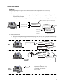
The design of the mounting structure/system depends on the mounting methods, as well as on the
sign’s size and weight. The design is critical and should be done only by a qualified individual/organization.
The mounting height of the sign and potential wind conditions are also critical factors. It is the customer’s
responsibility to ensure that the structure and mounting system are adequate. Adaptive is not responsible for
the installation or the structural integrity of mounting structures done by others.
It is the responsibility of the installer to ensure that the mounting system and hardware are capable of supporting
the sign and that they comply with all locally-applicable codes and regulations.
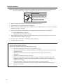
Follow these guidelines when installing the sign:
•
Consult with a professional sign installer to determine the proper mounting system and
installation and to comply with all locally-applicable codes and regulations.
•
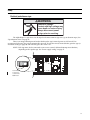
Only the factory-installed mounting support bars are to be used for mounting. Mounting to any
other parts of the sign will void the warranty.
•
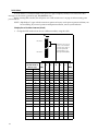
Drill holes as needed only in the mounting support bars for fasteners. Follow these guidelines for
structural integrity:
–
–
–
•
Drill only the minimum number of holes necessary.
Drilling any holes in the sign housing will void the warranty.
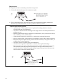
The distance from center line of the mounting bolt to the outside edge of the mounting
support bars should not be less than two times the diameter of the bolt.
– To prevent bi-metal corrosion, installation should provide for isolation of dissimilar materials
when mounting to the mounting support bars.
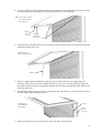
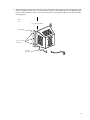
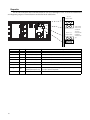
Lifting bolts should be used solely for the purpose of easing the installation process.
–
•
Lifting bolts are not to be used for permanently hanging or mounting the sign. Remove the
lifting bolts after installation.
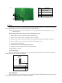
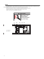
– Holes are provided for lifting bolts in the upper mounting support bar.
– A spreader bar should be used to maintain a vertical force on each lifting bolt to avoid
dangerous lateral force to the bolts.
Follow these guidelines when fastening the sign to the specific mounting structure:
–
–
•
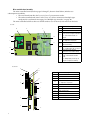
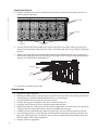
The unit must be mounted utilizing both upper and lower mounting support bars.
Fasteners are to be supplied by the installer according to the needs of the specific mounting
structure.
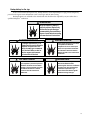
Allow 1.5 in. (4 cm) minimum clearance below fan covers to permit adequate circulation of air
flow for cooling and heating. Fans should not be obstructed in any way.
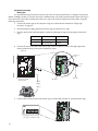
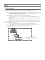
Conduit
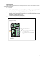
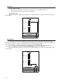
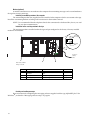
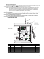
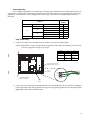
Separate 3/4” conduits must be run to the sign for power and for sign communications connections.
1.
Install conduit for power to the power line opening.
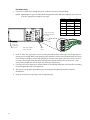
2.
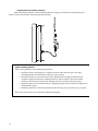
Install conduit to the sign communications and Temperature Probe opening if you:
3.
• mount the Control Box outside of the sign’s case for easier access, and/or
• install the Temperature Probe.
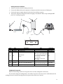
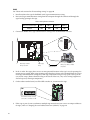
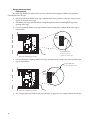
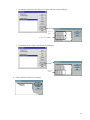
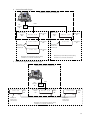
If there are two or more signs in a master-slave configuration, install a junction into the conduit for the
sign communications and Temperature Probe at the master sign. Then install conduit from the
junction to the slave sign(s) for the sign communications wiring.
29