1
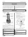
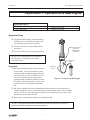
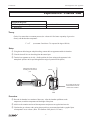
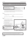
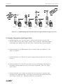
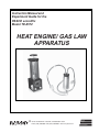
Instruction Manual and Experiment Guide for the PASCO scientific Model TD-8572 HEAT ENGINE/ GAS LAW APPARATUS ® 10101 Foothills Blvd. Roseville, CA 95678-9011 USA Phone (916) 786-3800 FAX (916) 786-8905 web: www.pasco.com better ways to teach science The exclamation point within an equilateral triangle is intended to alert the user of the presence of important operating and maintenance (servicing) instructions in the literature accompanying the appliance. 012-06014C Heat Engine/Gas Laws Apparatus Table of Contents Section Page Copyright, Warranty, and Equipment Return ....................................................ii Introduction ...................................................................................................... 1 Equipment ........................................................................................................ 1 Experiments 1) Operation of a Heat Engine ........................................................................ 3 2) Charles’ Law ............................................................................................. 5 3) Boyle’s Law .............................................................................................. 7 4) Combined Gas Law (Gay-Lussac’s) .......................................................... 9 5) The Mass Lifter Heat Engine ................................................................. 11–18 Technical Support ................................................................................... Back Cover ® i Heat Engine/Gas Laws Apparatus 012-06014C Copyright, Warranty, and Equipment Return Please—Feel free to duplicate this manual subject to the copyright restrictions below. Copyright Notice Equipment Return The PASCO scientific 012-06014B Heat Engine/Gas Law Apparatus manual is copyrighted and all rights reserved. However, permission is granted to non-profit educational institutions for reproduction of any part of the manual providing the reproductions are used only for their laboratories and are not sold for profit. Reproduction under any other circumstances, without the written consent of PASCO scientific, is prohibited. Should the product have to be returned to PASCO scientific for any reason, notify PASCO scientific by letter, phone, or fax BEFORE returning the product. Upon notification, the return authorization and shipping instructions will be promptly issued. ➤ NOTE: NO EQUIPMENT WILL BE ACCEPTED FOR RETURN WITHOUT AN AUTHORIZATION FROM PASCO. Limited Warranty When returning equipment for repair, the units must be packed properly. Carriers will not accept responsibility for damage caused by improper packing. To be certain the unit will not be damaged in shipment, observe the following rules: PASCO scientific warrants the product to be free from defects in materials and workmanship for a period of one year from the date of shipment to the customer. PASCO will repair or replace at its option any part of the product which is deemed to be defective in material or workmanship. The warranty does not cover damage to the product caused by abuse or improper use. Determination of whether a product failure is the result of a manufacturing defect or improper use by the customer shall be made solely by PASCO scientific. Responsibility for the return of equipment for warranty repair belongs to the customer. Equipment must be properly packed to prevent damage and shipped postage or freight prepaid. (Damage caused by improper packing of the equipment for return shipment will not be covered by the warranty.) Shipping costs for returning the equipment after repair will be paid by PASCO scientific. ➀ The packing carton must be strong enough for the item shipped. ➁ Make certain there are at least two inches of packing material between any point on the apparatus and the inside walls of the carton. ➂ Make certain that the packing material cannot shift in the box or become compressed, allowing the instrument come in contact with the packing carton. Address: PASCO scientific 10101 Foothills Blvd. Roseville, CA 95747-7100 Phone: FAX: email: web: (916) 786-3800 (916) 786-3292 [email protected] www.pasco.com Credits Editor: Sunny Bishop ii ® 012-06014C Heat Engine/Gas Law Apparatus Introduction The PASCO TD-8572 Heat Engine/Gas Law Apparatus is used for quantitative experiments involving the Ideal Gas Law (as described below) and for investigations of a working heat engine. The equipment allows the amount of work done by thermal energy to be measured. The heart of this apparatus is a nearly friction-free piston/ cylinder system. The graphite piston fits snugly into a precision-ground Pyrex cylinder so that the system produces almost friction-free motion and negligible leakage. Equipment The apparatus includes the following equipment • base apparatus (Figure 1) - piston diameter: 32.5 mm ± 0.1 - mass of piston and platform: 35.0 g ± .06 • air chamber (Figure 2) • 3 hose configurations: one with one-way check valves and one with a clamp (Figure 2), and one plain piece of tubing (not shown) mass platform for adding a load to do work experiments piston-holding thumbscrew precision-bore pyrex cylinder inside a protective plastic shield millimeter scale for measuring piston displacement • 1 each, one-holed and two-holed rubber stopper graphite piston tubing for connecting chamber to cylinder two port shut-off valves air chamber for immersing in hot or cold water pressure port mating connectors Figure 1. Base apparatus one-way check valves clamp The Heat Engine/Gas Law Apparatus is designed with two pressure ports with quick-connect fittings for connecting to the air chamber tubing. pressure port mating connectors The apparatus can be connected to a Low Pressure Sensor for use with PASCO computer interfaces. Figure 2. Air chamber and tubing Do not apply lubricant to the piston or cylinder. Always release the tubing clamps prior to storage to avoid permanently deforming the tubing. Do not immerse the base apparatus in liquid. Maximum Pressure: 345 kPa. Note: Use only non-caustic/non-toxic gases such as air or helium. ® 1 Heat Engine/Gas Law Apparatus 012-06014C Notes: 2 ® 012-06014C Heat Engine/Gas Law Apparatus Experiment 1: Operation of a Heat Engine Equipment Required: • Heat Engine/Gas Law Apparatus • 100 – 200 g mass • container of hot water • container of ice water Equipment Setup ➀ Using the one-holed stopper, connect the tubing m with the one-way valves to the air chamber and to a connecting port on the base assembly. ➁ Close the shut-off valve on the tubing from the Close the shut-off valve on the tubing from the unused port. unused port. ➂ Set a mass of 100 to 200 g on the mass platform. ➤ Note: Use a maximum mass of 200 grams in the experiment. A larger mass will cause the valve seals to leak. HEAT ENGINE GAS LAW APPARATUS TD-8572 Piston Dia.: 32.5mm±0.1 Piston&Platform Mass: 35.0g±0.6 CAUTION: Max. Pres.: 345 kPa. Use Gases Only DO NOT Immerse in any Liquid DO NOT Lubricate Piston or Cylinder Pressure Port Mating Connector: PASCO Part No. 640-021 Procedure one-way check valves direction of air flow ➀ Move the air chamber from an ice water bath to a hot water bath. You will note that the air in the chamber quickly expands through the tubing and moves the piston up. Note also that the one-way check valve in the tubing connecting the base apparatus and the air chamber permits air to enter the cylinder, while the other one-way check valve prevents air from leaving through the branched tube. Figure 1.1. Setup for the Heat Engine ➁ Move the air chamber back to the cold bath and note that external air is sucked into the air chamber through the one-way valve located at the end of the branched tube. Note also that the one-way valve in the connecting tube prevents the air from escaping from the piston, so the height of the piston remains the same. ➂ Repeat steps 3 and 4 until the mass has been completely lifted. ➤ Note: The greater the temperature differential between the hot and cold water baths, the greater the lift achieved through each cycle through them. ® 3 Heat Engine/Gas Law Apparatus 012-06014C ➤ Note: For a more detailed, quantitative investigation of the operation of a heat engine, see Experiment 5 (page 11). 4 ® 012-06014C Heat Engine/Gas Law Apparatus Experiment 2: Charles’ Law Equipment Required: • Heat Engine/Gas Law Apparatus • thermometer • container of hot water • ice Theory Charles’ law states that at a constant pressure, the volume of a fixed mass or quantity of gas varies directly with the absolute temperature: V = cT (at constant P and where T is expressed in degrees Kelvin) Setup ➀ Using the one-holed stopper and plain tubing, connect the base apparatus and the air chamber. ➁ Close the shut-off valve on the tubing from the unused port. ➂ Turn the base apparatus on its side. (In this position, the force acting on the apparatus is the atmospheric pressure and is equal throughout the range of operation of the piston.) Pressure Port Mating Connector: PASCO Part No. 640-021 TD-8572 Piston&Platform Mass: 35.0g±0.6 CAUTION: DO NOT Lubricate Piston or Cylinder Max. Pres.: 345 kPa. Use Gases Only DO NOT Immerse in any Liquid Add ice. Piston Dia.: 32.5mm±0.1 HEAT ENGINE GAS LAW APPARATUS Close the shut-off valve on the tubing from the unused port. Do not allow the tip of the thermometer to touch the bottom of the container. Hot Procedure ➀ Place the air chamber in a container of hot water. After the chamber equilibrates to the temperature, record the temperature and the height of the piston. ➁ Add ice to the container and record the temperature and pressure at regular time intervals. ➂ Calculate the gas volumes at the various piston positions you measured and make a graph of plots of temperature versus volume. (Hint: The diameter of the piston is 32.5 mm.) ® 5 Heat Engine/Gas Law Apparatus 012-06014C Notes: 6 ® 012-06014C Heat Engine/Gas Law Apparatus Experiment 3: Boyle’s Law Equipment Required: • Science Workshop computer interface* • Heat Engine/Gas Law Apparatus • Pressure Sensor (CI-6532) *For details on setting up and operating the Pressure Sensor with Science Workshop, please consult the instruction sheet for the Pressure Sensor and the User’s Guide for Science Workshop. Theory Boyle’s law states that the product of the volume of a gas times its pressure is a constant at a fixed temperature: PV = a Therefore, at a fixed temperature, the pressure will be inversely related to the volume, and the relationship will be linear: a P = V Setup ➀ With the platform raised to its uppermost position, connect the Pressure Sensor to a port on the base apparatus with a short piece of tubing (Figure 3.1). ➁ Close the shut-off valve on the tubing from the unused port. ➂ Connect the Pressure Sensor to the computer interface and set up Science Workshop to record pressure. Be sure that you set up the keyboard sampling option so you can enter height data by hand. (Consult the Science Workshop User’s Guide, “Keyboard Sampling,” for details.) to computer interface HEAT ENGINE GAS LAW APPARATUS TD-8572 Piston Dia.: 32.5mm±0.1 Close the shut-off valve on the tubing from the unused port. Piston&Platform Mass: 35.0g±0.6 CAUTION: Max. Pres.: 345 kPa. Use Gases Only DO NOT Immerse in any Liquid DO NOT Lubricate Piston or Cylinder CE TO FA ER INT RE SU OR ES NS kPa E) PR SE 700 OLUT 0- Procedure O SCIE PASER 2 53 CI-6 0 C RFA 650 INTE E Pressure Port Mating Connector: PASCO Part No. 640-021 BS (A LY ON TTOR: 21 POR RE NEC 640-0 Y AIR SSUCON NO. PREING PART DR MAT O PASC RE X SU ES RT MA PR POkPa 0 70 ➀ Record the height of the piston and the pressure when the platform is raised to its highest position. Pressure Sensor ➁ Press the platform down to a series of levels and record the height and pressure at each level. ➂ Convert the height measurements to gas volume Figure 3.1. Experimental setup measurements. (Hint: The diameter of the piston is 32.5 mm.) ➃ Prepare a graph of pressure versus volume. ➤ Note: The relationship between pressure and volume may not be linear at pressures greater than 120 kPa because of air leakage from the valves and ports at higher pressures. ® 7 Heat Engine/Gas Law Apparatus 012-06014C 8 ® 012-06014C Heat Engine/Gas Law Apparatus Experiment 4: Combined Gas Law (Gay-Lussac’s ) Equipment Required: • Pressure Sensor (CI-6532) • Science Workshop computer interface* • Temperature Sensor (CI-6505) • hot plate • Pyrex beaker with water • ice *For details on setting up and operating the Pressure Sensor and the Temperature Sensor with Science Workshop, please consult the instruction sheets for the Pressure Sensor and the Temperature Sensor and the User’s Guide for Science Workshop. Theory Charles’ law states that V is proportional to T, and Boyle’s law states that V is proportional to 1/P. Combining these, we have: aT V= P The combined gas law predicts that for a given mass of gas, if V is held constant, P is proportional to T. Setup ➀ The Gas Law Apparatus is not used in this experiment. Use a short piece of tubing to connect the pressue sensor to the air chamber fitted with the 2-hole stopper. ➁ Insert the Temperature Sensor into the other hole of the rubber stopper. to computer interface ➂ Connect the Pressure Sensor and the Tem- to computer interface perature Sensor to the computer interface, and set up the Science Workshop program to graph temperature versus pressure. Use a silicon lubricant on the end of the Temperature Probe to aid insertion and to prevent damage to the probe. Temperature Sensor E TO AC ERF INT RE SU R ES NSOkPaUTE) 00 OL PR SE0-7 -653 CO PAS SERIE 2 CI 0FAC 650 INTER E (A BS LY ON R: 21 PORT ECTO 640-0 Y AIRSURE CONNNO. PRES G PART DR MATIN O PASC RE X SU ES RT MA PR POkPa 700 Pressure Sensor hot plate ➃ Place the air chamber in the Pyrex container and turn on the hot plate. Figure 4.1. Experimental setup ➤ Note: You can substitute a thermometer in the water container for the Temperature Sensor. Be sure to keep the tip of the thermometer from touching the bottom of the container. ® 9 Heat Engine/Gas Law Apparatus 012-06014C Procedure ➀ Record the temperature and pressure as the water heats. ➁ Display a graph of temperature versus pressure in Science Workshop. 10 ® 012-06014C Heat Engine/Gas Law Apparatus Experiment 5: The Mass Lifter Heat Engine1 The Heat Engine/Gas Law Apparatus is ideal for use in the calculus-based experiment 18.10 of the Workshop Physics Activity Guide. Following is a slightly modified reprint of the experiment: Equipment Required: • • • • Heat Engine/Gas Law Apparatus 2 Pyrex beakers, 1000 ml (to use as reservoirs) 1 ruler 1 barometer pressure gauge • • • • 1 calipers 1 mass set, 20 g, 50 g, 100 g, 200 g 1 hot plate 1 vat to catch water spills Optional: • a computer-based laboratory system with barometer sensor Your working group has been approached by the Newton Apple Company about testing a heat engine that lifts apples that vary in mass from 100 g to 200 g from a processing conveyer belt to the packing conveyer belt that is 10 cm higher. The engine you are to experiment with is a "real" thermal engine that can be taken through a four-stage expansion and compression cycle and that can do useful mechanical work by lifting small masses from one height to another. In this experiment we would like you to verify experimentally that the useful mechanical work done in lifting a mass, m, through a vertical distance, y, is equal to the net thermodynamic work done during a cycle as determined by finding the enclosed area on a P-V diagram. Essentially you are comparing useful mechanical “magy” work (which we hope you believe in and understand from earlier studies) with the accounting of work in an engine cycle as a function of pressure and volume changes given by the expression: Wnet = PdV Although you can prove mathematically that this relationship holds, the experimental verification will allow you to become familiar with the operation of a real heat engine. m c b y P m d a 0 V Figure 5.1. Doing useful mechanical work by lifting a mass, m, through a height, y. 1 Figure 5.2 Doing thermodynamic work in a heat engine cycle. Priscilla W. Laws, et al. Workshop Physics Activity Guide, 1996 by John Wiley & Sons, Inc. Reprinted by permission of John Wiley & Sons, Inc. ® 11 Heat Engine/Gas Law Apparatus 012-06014C The Incredible Mass Lifter Engine The heat engine consists of a hollow cylinder with a graphite piston that can move along the axis of the cylinder with very little friction. The piston has a platform attached to it for lifting masses. A short length of flexible tubing attaches the cylinder to an air chamber (consisting of a small can sealed with a rubber stopper that can be placed alternately in the cold reservoir and the hot reservoir. A diagram of this mass lifter is shown in Figure 5.2. m Close the shut-off valve on the tubing from the unused port. HEAT ENGINE GAS LAW APPARATUS TD-8572 Piston Dia.: 32.5mm±0.1 Piston&Platform Mass: 35.0g±0.6 CAUTION: Max. Pres.: 345 kPa. Use Gases Only DO NOT Immerse in any Liquid DO NOT Lubricate Piston or Cylinder Pressure Port Mating Connector: PASCO Part No. 640-021 Hot Cold Figure 5.2. A schematic diagram of the incredible mass lifter heat engine. If the temperature of the air trapped inside the cylinder, hose, and can is increased, then its volume will increase, causing the platform to rise. Thus, you can increase the volume of the trapped air by moving the can from the cold to the hot reservoir. Then, when the apple has been raised through a distance y, it can be removed from the platform. The platform should then rise a bit more as the pressure on the cylinder of gas decreases a bit. Finally, the volume of the gas will decrease when the air chamber is returned to the cold reservoir. This causes the piston to descend to its original position once again. The various stages of the mass lifter cycle are shown in Figure 5.3. Before taking data on the pressure, air volume, and height of lift with the heat engine, you should set it up and run it through a few cycles to get used to its operation. A good way to start is to fill one container with room temperature water and another with hot tap water or preheated water at about 60–70°C. The engine cycle is much easier to describe if you begin with the piston resting above the bottom of the cylinder. Thus, we suggest you raise the piston a few centimeters before inserting the rubber stopper firmly in the can. Also, air does leak out of the cylinder slowly. If a large mass is being lifted, the leakage rate increases, so we suggest that you limit the added mass to something between 100 g and 200 g. After observing a few engine cycles, you should be able to describe each of the points a, b, c, and d of a cycle carefully, indicating which of the transitions between points are approximately adiabatic and which are isobaric. You can observe changes in the volume of the gas directly and you can predict how the pressure exerted on the gas by its surroundings ought to change from point to point by using the definition of pressure as force per unit area. 12 ® 012-06014C Heat Engine/Gas Law Apparatus m m m 0 Point A m 0 0 Point B Cold y y Point C Cold Point D Hot Hot Figure 5.3. A simplified diagram of the mass lifter heat engine at different stages of its cycle. 5.1 Activity: Description of the Engine Cycle a. Predicted transition a➔ b: Close the system to outside air but leave the can in the cold reservoir. Make sure the rubber stopper is firmly in place in the can. What should happen to the height of the platform when you add a mass? Explain the basis of your prediction. b. Observed transition a➔ b: What happens when you add the mass to the platform? Is this what you predicted? c. Predicted transition b➔ c: What do you expect to happen when you place the can in the hot reservoir ? d. Observed transition b➔ c: Place the can in the hot reservoir and describe what happens to the platform with the added mass on it. Is this what you predicted? (This is the engine power stroke!) e. Predicted transition c➔ d: Continue to hold the can in the hot reservoir and predict what will happen if the added mass that is now lifted is removed from the platform and moved onto an upper conveyor belt. Explain the reasons for your prediction. ® 13 Heat Engine/Gas Law Apparatus 012-06014C f. Observed transition c➔ d: Remove the added mass and describe what actually happens. Is this what you predicted? g. Predicted transition d➔ a: What do you predict will happen if you now place the can back in the cold reservoir? Explain the reasons for your prediction. h. Observed transition d➔ a: Now it's time to complete the cycle by cooling the system down to its original temperature for a minute or two before placing a new mass to be lifted on it. Place the can in the cold reservoir and describe what actually happens to the volume of the trapped air. In particular, how does the volume of the gas actually compare to the original volume of the trapped air at point a at the beginning of the cycle? Is it the same or has some of the air leaked out? i. Theoretically, the pressure of the gas should be the same once you cool the system back to its original temperature. Why? Determining Pressures and Volumes for a Cycle In order to calculate the thermodynamic work done during a cycle of this engine, you will need to be able to plot a P-V diagram for the engine based on determinations of the volumes and pressures of the trapped air in the cylinder, tubing, and can at the points a, b, c, and d in the cycle. 5.2 Activity: Volume and Pressure Equations a. What is the equation for the volume of a cylinder that has an inner diameter of d and a length L? b. Use the definition of pressure to derive the equation for the pressure on a gas being contained by a vertical piston of diameter d if the total mass on the piston including its own mass and any added mass is denoted as M. Hints: (1) What is the definition of pressure? (2) What is the equation needed to calculate the gravitational force on a mass, M, close to the surface of the Earth? (3) Don't forget to add in the atmospheric pressure, Patm, acting on the piston and hence the gas at sea level. Now that you have derived the basic equations you need, you should be able to take your engine through another cycle and make the measurements necessary for calculating both the volume and the pressure of the air and determining a P-V diagram for your heat engine. Instead of calculating the pressures, if you have the optional equipment available, you might want to measure the pressures with a barometer or a barometer sensor attached to a computerbased laboratory system. 14 ® 012-06014C Heat Engine/Gas Law Apparatus 5.3 Activity: Determining Volume and Pressure a. Take any measurements needed to determine the volume and pressure of air in the system at all four points in the engine cycle. You should do this rapidly to avoid air leakages around the piston and summarize the measurements with units in the space below. b. Next you can use your measurements to calculate the pressure and volume of the system at point a. Show your equations and calculations in the space below and summarize your results with units. Don't forget to take the volume of the air in the tubing and can into account! Pa= Va= c. Use the measurements at point b to calculate the total volume and pressure of the air in the system at that point in the cycle. Show your equations and calculations in the space below and summarize your results with units. Pb= Vb= d. What is the height, y, through which the added mass is lifted in the transition from b to c? e. Use the measurements at point c to calculate the total volume and pressure of the air in the system at that point in the cycle. Show your equations and calculations in the following space and summarize your results with units. Pc= Vc= ® 15 Heat Engine/Gas Law Apparatus 012-06014C f. Remove the added mass and make any measurements needed to calculate the volume and pressure of air in the system at point d in the cycle. Show your equations and calculations in the space below and summarize your results with units. Pd= Vd= g. We suspect that transitions from a➔ b and from c➔ d are approximately adiabatic. Explain why. h. You should have found that the transitions from b➔ c and from d➔ a are isobaric. Explain why this is the case. Finding Thermodynamic Work from the Diagram In the next activity you should draw a P- V diagram for your cycle and determine the thermodynamic work for your engine. 5.4 Activity: Plotting and Interpreting a P-V Diagram a. Fill in the appropriate numbers on the scale on the graph frame that follows and plot the P-V diagram for your engine cycle. Alternatively, generate your own graph using a computer graphing routine and affix the result in the space below. 16 ® 012-06014C Heat Engine/Gas Law Apparatus b. On the graph in part a, label each of the points on the cycle (a, b, c, and d). Indicate on the graph which of the transitions (a➔ b, b➔ c, etc.) are adiabatic and which are isobaric. Next you need to find a way to determine the area enclosed by the P- V diagram. The enclosed area doesn't change very much if you assume that P is approximately a linear function of V for the adiabatic transitions. By making this approximation, the figure is almost a parallelogram so you can obtain the enclosed area using one of several methods. Three of the many possibilities are listed below. Creative students have come up with even better methods than these, so you should think about your method of analysis carefully. Method I Since the pressure doesn't change from point b to point c, you can take the pressure of those two points as a constant pressure between points. The same holds for the transition from d to a. This gives you a figure that is approximately a parallelogram with two sets of parallel sides. You can look up and properly apply the appropriate equation to determine the net thermodynamic work performed. Method II Display your graph with a grid and count the boxes in the area enclosed by the lines connecting points a, b, c, and d. Then multiply by the number of joules each box represents. You will need to make careful estimates of fractions of a box when a "leg" of a cycle cuts through a box. Method III b PdV = c PdV + a d PdV + b a PdV + c PdV d Fit a straight line to each of the starting and ending points for the four transitions in the cycle. Each equation will give you a function relating P and V. Perform an integral for each of these equations, since 5.5 Activity: Comparing the Thermodynamic and Useful Mechanical Work a. Choose a method for computing the thermodynamic work in joules, describe it in the space below, and show the necessary calculations. Report the result in joules. ® 17 Heat Engine/Gas Law Apparatus 012-06014C b. What is the equation you need to use to calculate the useful mechanical work done in lifting the mass from one level to another? c. Use the result for the height that the mass is lifted in the power stroke of the engine to calculate the useful mechanical work performed by the heat engine. d. How does the thermodynamic work compare to the useful mechanical work? Please use the correct number of significant figures in your comparison (as you have been doing all along, right?) The Incredible Mass Lifter Engine Is Not So Simple Understanding the stages of the engine cycle on a P-V diagram is reasonably straightforward. However, it is difficult to use equations for adiabatic expansion and compression and the ideal gas law to determine the temperature (and hence the internal energy of the air throughout the cycle. There are several reasons for this. First, air is not an ideal gas. Second, the mass lifter engine is not well insulated and so the air that is warmed in the hot reservoir transfers heat energy through the cylinder walls. Thus, the air in the can and in the cylinder are probably not at the same temperature. Third, air does leak out around the piston, especially when larger masses are added to the platform. This means that the number of moles of air decreases over time. You can observe this by noting that in the transition from point d to point a, the piston can actually end up in a lower position than it had at the beginning of the previous cycle. However, the Incredible Mass Lifter Engine does help us understand typical stages of operation of a real heat engine. ➤ Note: The previous experiment was intended to help students consolidate the concepts of pressure and volume by taking their own data for height and mass in each part of the cycle and then calculating the pressures using the basic definition of pressure vs. force per unit area. An alternate method for doing this experiment is to use the Science Workshop computer interface with the Pressure Sensor (CI-6532) in conjunction with either a Motion Sensor (CI-6529) or Rotary Motion Sensor (CI-6538) to detect pressure, volume, and height automatically with a computer. 18 ® Technical Support Feedback Contacting Technical Support If you have any comments about the product or manual, please let us know. If you have any suggestions on alternate experiments or find a problem in the manual, please tell us. PASCO appreciates any customer feedback. Your input helps us evaluate and improve our product. Before you call the PASCO Technical Support staff, it would be helpful to prepare the following information: ➤ If your problem is with the PASCO apparatus, note: - Title and model number (usually listed on the label); To Reach PASCO - Approximate age of apparatus; For technical support, call us at 1-800-772-8700 (toll-free within the U.S.) or (916) 786-3800. - A detailed description of the problem/sequence of fax: (916) 786-3292 e-mail: [email protected] web: events. (In case you can’t call PASCO right away, you won’t lose valuable data.); - If possible, have the apparatus within reach when calling to facilitate description of individual parts. www.pasco.com ➤ If your problem relates to the instruction manual, note: - Part number and revision (listed by month and year on the front cover); - Have the manual at hand to discuss your questions.