1
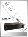
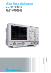
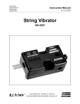
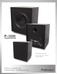
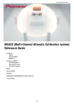
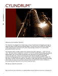
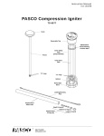
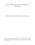
Instruction Manual
012-10425A
Function Generator
PI-8127
Waveform
Selection
button
Frequency Adjust
knob and Range
Selection button
Menu
button
Voltage
Adjust
knob and
Menu
Selection
button
Liquid
Crystal
Display
(LCD)
Power
button
Included Equipment
Output
Standby
button
Resolution
Selection
buttons
Output
jacks
(4 mm)
Part Number
Function Generator
AC to 15 V DC, 1.6 A power adapter (not shown)
540-057
Examples of Compatible PASCO Equipment
(See the PASCO Catalog for details)
Mechanical Wave Driver
SF-9324
Open Speaker
WA-9900
AC/DC Electronics Laboratory
EM-8656
RLC Circuit Board
CI-6512
®
Function Generator
Introducti on
Introduction
The PASCO Function Generator outputs waveforms that include DC (direct current)
as well as sine, square, triangle, positive ramp, and negative ramp with a frequency
range of 0.001 Hz (hertz) to 100 kHz (kilohertz). The sine waveworm retains its form
up to a frequency of 150 kHz, but the other waveforms will show some distortion
above 100 kHz. Its 10 watt power output (up to 10 volts and up to 1 amp) makes it
useful for driving speakers, string vibrators, and circuits.
Features
Liquid Crystal Display (LCD): The liquid crystal display (LCD) shows
frequency, voltage, current, and waveform. The lower right section of the
LCD also shows other information such as the voltage offset of the output, if any, whether a frequency sweep is on, and whether the output is on
standby.
LCD shows frequency, voltage,
Frequency/Range Selection: There are two frequency ranges: 0.001 Hz current, and waveform as well as other information
such as the voltage offset and sweep condition.
to 999.999 Hz, and 0.001 kHz to 100.000 kHz (150 kHz for the sine
waveform). When the Function Generator is first turned on, the default
frequency is 1.000 kHz. Press the Frequency Adjust knob as if it were a button to
switch between ranges.
Output Standby: Pushing the Output Standby button disables the output without
changing settings. This allows you to change settings with the output off. Press the
button again to enable the output.
Output Current/Voltage Maximum: The maximum current or maximum voltage
can be set using a menu. This is useful when the voltage applied to a circuit needs to
be limited. The LCD displays the output voltage and current.
Offset Voltage: Any waveform can be offset up or down with a DC voltage ranging
from -10 V to +10 V, provided the peak voltage does not exceed 10 V.
Frequency Sweep: Sweep between two frequencies at a selectable rate.
Operation
Power: Connect the plug from the AC-to-15 V DC adapter to the power jack on the
lower right corner of the back panel of the Function Generator. Connect the power
cord for the adapter to an appropriate electrical outlet.
Power jack
On/Off: To turn the Function Generator on, press the Power button on the
lower left corner of the front panel. Press the Power button again to turn
the Function Generator off.
Default Settings: The displayed default settings when the Function Generator is first turned on are 1.000 kHz (frequency), 0.00 V (output voltage), 0.00 A (output current), and sine wave (waveform). The waveform
symbol is shown at the lower left corner of the LCD.
Displayed Default Settings
Settings that are not shown by default are the voltage offset (0.00 V) and
the voltage limit (maximum voltage), which is 10.0 V, the short circuit current limit
(maximum current), which is 1.50 A, the backlight setting (“High”), and the sweep
setting (“Off”). See the Menus section for more information.
2
®
Model No.PI-8127
Output: Connect a device such as a speaker, wave driver, or electrical circuit to the
output jacks at the lower right corner of the front panel.
Frequency Adjust
Operation
NOTE:
To set up the frequency, voltage, and other parameters
without outputting a signal,
press the OUTPUT
STANDBY button.
The Frequency Adjust knob serves two purposes. Turn the knob to change the frequency. Press the end of the knob as if it were a button to toggle between the two fre- Make the adjustments, and
press the OUTPUT
quency ranges.
Range Selection: The default range is 0.001 kHz to 100.000 kHz or 150.000 kHz for
the sine waveform (other waveforms are distorted above 100 kHz). The other range is
0.001 Hz to 999.999 Hz. Press the end of the Frequency Adjust knob as if it were a
button to switch between ranges. The default frequency for the lower range is 1.000
Hz.
STANDBY button again to
begin the signal.
Frequency Adjust: The default frequency for the default range is 1.000 kHz. Notice
that the “1” is underlined in the display. This indicates that this is the digit that will
change first when you turn the knob. For example, turn the knob one “click” to the
right (clockwise), and the frequency increases to 2.000 kHz. Each “click” to the right
(clockwise) or left (counterclockwise) will increment or decrement the digit that is
underlined in the display. When you reach 9.000 kHz, the next “click” to the right
Press the Frequency Adjust
will change the frequency to 10.000 kHz. Notice that the underline stays
knob to change the range.
below the “ones” place. Turning the frequency knob one more “click” to the
right changes the frequency to 11.000 kHz.
As a second example, if the frequency is 1.000 kHz, turning the Frequency Adjust
knob one “click” to the left (counterclockwise) does not decrease the frequency to
0.000 kHz. Instead, the frequency stays at 1.000 kHz (it is not possible to have zero
frequency). To lower the frequency, press the right-hand Resolution Selection button
to move the underline to the right (1.000 kHz) and then turn the Frequency Adjust
knob counterclockwise one “click” to decrease the frequency to 0.900 kHz.
NOTE: You can conveniently go
to the lowest frequency without
overshooting by rapidly turning
the Frequency Adjust knob.
Resolution Selection: Use the Resolution Selection buttons beneath the Frequency
Adjust knob to change the active (underlined) digit in the display. Pushing the left
button moves the underline to the left and pushing the right button moves the underline to the right.
Use both the Frequency Adjust knob and the Resolution Selection buttons to set the
frequency. Remember that you can push the OUTPUT STANDBY button to disable
the output while you adjust the frequency, and then push the button again to enable
the output when you have the frequency set the way you want.
Resolution Selection buttons
Clear Feature: While adjusting the frequency, you can clear (zero) all the digits to
the right of the underline cursor by pressing the Voltage Adjust knob as if it were a
button.
Voltage Adjust
The Voltage Adjust knob serves three purposes.
•
Turn the knob to change the output voltage.
•
When the LCD shows the waveform list or the menu, turn the Voltage Adjust
knob to move the pointer up or down in the list or in the menu.
•
Press the knob as if it were a button to select a choice from the waveform list or
from the menu.
®
Press the Voltage Adjust
knob to select a waveform
or menu item
3
Function Generator
Operation
Voltage Adjust: To move the underline from the Frequency part of the
LCD to the Voltage part of the LCD, turn the Voltage Adjust knob one
“click” to the left or right. Notice that the underline is below the “ones”
place in the display (0.00 V). Turn the knob one “click” to the right
(clockwise) to increase the voltage output.
Each “click” to the right (clockwise) or left (counterclockwise) will increment or decrement the digit that is underlined in the display. When you
reach 9.00 V the next “click” to the right will change the voltage to 10.00
V. Notice that the underline stays below the “ones” place.
Voltage Adjust display
Resolution Selection: Use the Resolution Selection buttons below the Frequency
Adjust knob to change the active (underlined) digit in the voltage display. Pushing the
left button moves the underline to the left and pushing the right button moves the
underline to the right.
Use both the Voltage Adjust knob and the Resolution Selection buttons to set the volt- Resolution Selection buttons
age. Remember that you can push the OUTPUT STANDBY button to disable the output while you adjust the voltage, and then push the button again to enable the output
when you have the voltage set the way you want.
To move the underline back to the Frequency part of the LCD, turn the Frequency
Adjust knob one “click” to the left or right.
Waveforms
Press the WAVEFORM button to open the first waveform menu. The menu shows
five choices (Sine, Square, Triangle, Positive Ramp, and Negative Ramp) with the
pointer at Sine. Turn the Voltage Adjust knob one “click” to the left (counterclockwise) to move the pointer from Sine to Square. Press the Voltage Adjust knob as if it
were a button to select the choice. The LCD will show the Square wave icon in the
lower left corner.
First WAVEFORM menu
Sine, Square, Triangle, Positive Ramp, and Negative Ramp waveforms. Frequency: 1.000 kHz. Voltage: 2.00 V.
Vertical scale: 1 V/div. Horizontal scale: 1 ms/div.
Press the WAVEFORM button again to return to the first waveform menu. Notice the
down pointing arrow at the lower left corner. This indicates that there are more
choices on the menu. Turn the Voltage Adjust knob counterclockwise to move the
pointer to Negative Ramp. Turn the knob one more “click” counterclockwise to show
the next choice in the menu, DC (or direct current). Notice that the menu now has an
“up” pointing arrow at the upper left corner as well as the down pointing arrow in the
lower left corner.
Next WAVEFORM menu
DC: Press the Voltage Adjust knob to select the DC choice. Notice that the LCD
shows only voltage and current. Turn the Voltage Adjust knob to increase or decrease
the voltage (±10 V maximum).
4
®
Model No.PI-8127
Operation
DC voltage
adjust
screen
Continue to turn the Voltage Adjust knob counterclockwise to reveal the next five
waveform choices: External, Mod Sine, Mod Triangle, Mod Pos Ramp, and Mod Neg
Ramp. (“Mod” is an abbreviation for “modulated”.)
Last WAVEFORM menu
External Input: The External waveform choice corresponds to the use of an external
input to the Function Generator. The generator has positive and negative input jacks
on the rear panel. Maximum input voltage is ±10 V. The Function Generator amplifies
the power of the input signal up to a maximum of 10 watts (up to 1 amp at up to 10
volts), expressed as a percentage of maximum. Turn the Voltage Adjust knob to
decrease or increase the power amplification.
Percent
modulation
External
waveform
display
Modulated Waveforms: The modulated (Mod) waveform choices also correspond
to the use of an external input to the Function Generator through the input jacks on
the rear panel. When a modulated (Mod) waveform is selected, the signal produced
by the Function Generator will be multiplied by the signal from the external input.
Mod Sine
waveform
display
Change the frequency of the Function Generator’s signal with the Frequency Adjust
knob. Adjust the percent modulation with the Voltage Adjust knob. The formula for
the percent modulation is based on the amplitudes of the peak (P) and the trough (T)
of the modulated signal.
P-T
percent modulation = ------------ × 100
P +T
When the percent modulation is 100%, the trough amplitude is zero.
Mod Sine waveform. Input signal
is 1 kHz at 2.00 V. Mod Sine signal
is 0.100 kHz at 100%.
Menus
Press the MENU button to show the list of choices: V Offset (voltage offset), V Limit
(voltage limit), I Limit (short circuit current limit), Backlight, and Sweep. The pointer
is at V Offset. Turn the Voltage Adjust knob to move the pointer up or down among
the choices. Press the Voltage Adjust knob as if it were a button to select a choice.
®
MENU choices
5
Function Generator
Operation
V Offset (voltage offset): The default voltage offset in the Voltage Offset display is
0.00 V. Use the Voltage Adjust knob and the Resolution Buttons to increase or
decrease the DC voltage. Any waveform can be offset up or down with a DC voltage
ranging from -10 V to +10 V, provided the peak voltage does not exceed 10 V.
Press the MENU button or the
Voltage Adjust knob to return
to the MENU choices.
Press the MENU button again
to return to the screen before
the MENU button was
pressed the first time.
Voltage
Offset
display
V Limit (voltage limit): The default maximum voltage in the Voltage Limit display
is 10.00 V. Use the Voltage Adjust knob and the Resolution Selection buttons to
change the maximum voltage from 10.00 V to another voltage. The minimum voltage
is 0.00 V.
Voltage
Limit
display
I Limit (current limit): The default maximum current in the Current Limit display is
1.50 A. Turn the Voltage Adjust knob to change the maximum current from 1.50 A to
1.10 A or to 0.55 A. Press the Voltage Adjust knob as if it were a button to select the
current limit. Setting the maximum current is useful when there needs to be a limit to
the current applied to a circuit. This is a safety feature to protect against short circuit
overload.
NOTE: As the current approaches
the limit, “Overcurrent” will be displayed at the bottom of the LCD. The
“Overcurrent” warning will be displayed at approximately 1.2 A for the
1.50 A limit, 1.0 A for the 1.10 A limit,
and 0.5 A for the 0.55 A limit.
Current
Limit
display
Backlight: The default backlight setting is “High”. Use the Voltage Adjust knob to
select the menu choice. Press the Voltage Adjust knob as if it were a button to toggle
(switch) to the other choice: “Low”. The Low setting is useful when the Function
Generator is in a darkened environment.
Sweep: Turn the Voltage Adjust knob so the pointer is next to Sweep and then press
the knob as if it were a button to select the choice. The default setting is “Off”.
Backlight Low
The Sweep menu options offer several ways to tailor the output signal for specific
needs. The Sweep function is set up so that the output signal begins at a specific frequency (Initial) and ends at another specific frequency (Final). The ‘sweep’ between
frequencies can be set to last for a certain time (Duration), and the step frequency
(Step) can also be set for a specific amount..
The Sweep function can be set to one of the following:
•
6
Sweep options
Off: The default setting.
®
Model No.PI-8127
Operation
•
Single: The frequency ‘sweeps’ from the initial frequency to the final frequency
one time.
•
Repeat: The frequency ‘sweeps’ between the initial and final frequencies repeatedly.
•
Bidir (bidirectional): The frequency sweeps from the initial frequency to the final
frequency and then back to the initial frequency repeatedly.
Press the Voltage Adjust knob as if it were a button to ‘step through’ the Sweep
choices. Press the MENU button to return to the previous display, or use the Voltage
Adjust knob to move the pointer to another choice.
Sweep bidirectional
Initial: The default initial frequency is 100.000 Hz. Turn the Voltage Adjust knob so
the pointer is next to ‘Initial’ and then press the knob to select the choice. Use the Frequency Adjust knob and the Resolution Selection buttons to set the initial frequency.
Remember that you can press the Frequency Adjust knob as if it were a button to
switch frequency ranges. Press the Voltage Adjust knob again to return to the menu of
Sweep options. .
Initial Frequency display
Final: The default final frequency is 500.000 Hz. As with the initial frequency, use
the Voltage Adjust knob to select the choice, and the Frequency Adjust knob and Resolution Selection buttons to set the final frequency. Press the Voltage Adjust knob as
if it were a button to return to the menu of Sweep options. .
Duration: The default duration for the sweep is 5 seconds. As with the initial frequency, use the Voltage Adjust knob to select the choice. Use the Voltage Adjust knob
and the Resolution Selection buttons to change the duration time. The minimum is 1
second and the maximum is 9999 seconds (2 h, 46 min, 39 s). Press the Voltage
Adjust knob as if it were a button to return to the menu of Sweep options..
Step: The default step frequency is ‘None’. This means that the default frequency
sweep will be continuous from the initial to the final frequency. As with the initial frequency, use the Voltage Adjust knob to select ‘Step’ and press the knob as if it were a
button. Use the Frequency Adjust knob and the Resolution Selection buttons to
change the step frequency. The range for the step frequency is from 0.001 Hz to
100.000 kHz (or 150 kHz for the Sine waveform). In general it is best to pick a step
frequency that is less than the difference between the initial and final frequencies.
Step
Frequency
display
In general it is best to
pick a step frequency that
is less then the difference
between the initial and
final frequencies.
Final Frequency display
Duration display
Remember, you can press the
Frequency Select knob as if it were a
button to switch the frequency range.
Press the Voltage Adjust knob as a button to return to the menu of Sweep options.
Press the MENU button to exit the menu of Sweep options, and press the MENU button again to exit the main menu.
Standby: When a sweep function other than ‘Off’ is selected, the generator automatically goes into the ‘Standby’ condition. That is, the generator
will not output its signal until the OUTPUT STANDBY button is pressed.
Press the OUTPUT STANDBY button again to disable the output..
The Example display shows Frequency at 100.000 Hz, Voltage at 2.00 V,
output current at 0.00 A, V Offset (voltage offset) at 1.00 V, Sine waveform, Sweep function is ‘On’, and the generator’s output is on ‘Standby’.
®
Example display
7
Function Generator
Some Suggested Uses
Other
Current
Several displays show the root mean square (‘rms’) output current (0.00A rms). The
Function Generator calculates the true root mean square of the output current, not just
the peak current divided by the square root of two. The output current depends on the
output voltage and the resistance of the device or circuit to which the generator is connected. For example, if you set the generator to output 5.00 V DC and connect the
output to a 10 ohm resistor, the output current display will show approximately 0.50A
rms. If you change to a Sine Wave, the current will read 0.707 x 0.5A = 0.35A rms.
The name “root mean square”
comes from the fact that it is the
square root of the mean of the
squares of the values.
Trigger Output
On the rear panel is a BNC connector labeled TRIGGER OUT (TTL). If you want to
trigger an oscilloscope synchronously with the generator output, just connect the
TRIGGER OUT (TTL) connector to the external trigger of the oscilloscope (cable not
included).
USB Port for Firmware Update
Next to the TRIGGER OUT (TTL) connector on the rear panel is a USB port. The
USB port allows a USB cable (not included) to be connected from a computer to the
Function Generator so that its firmware can be updated. Go to
www.pasco.com/downloads for instructions.
USB Port
Some Suggested Uses
In addition to the usual uses of a function generator such as providing sine wave signals for electronics laboratories, the PI-8127 Function Generator is particular suited
for experiment in waves and acoustics.
Drive a speaker - or several speakers - with the Function Generator. Accurately set the
frequency to any level in the acoustic range or beyond. This makes it particularly convenient for experiments such as measuring the speed of sound, observing the interference and diffraction of sound waves, and investigating acoustic resonance in a cavity.
Use the Function Generator with the PASCO Resonance Tube (see www.pasco.com)
to investigate resonant modes and the speed of sound in a closed or open tube.
Use the Function Generator with the PASCO Sonometer and Driver/Detector Coils to
measure resonant frequencies and harmonics and the location of nodes and antinodes
on a wire.
The built-in amplifier makes it an ideal device for driving mechanical
wave experiments. Use the generator with a PASCO Mechanical Wave
Driver to examine the resonance modes in a vibrating wave cord. Experiment with the motion of waves in two dimensions by using sand on the
thin metal plates of the PASCO Chladni Plate Kit.
Use the generator with the PASCO Coupled Harmonic Oscillators to study
coupled harmonic motion of two or more gliders on an air track.
Connect the Function Generator to a resistor-capacitor (RC) circuit such
as the PASCO RLC Circuit Board and measure the voltage across the
resistor as the generator drives the circuit with a square wave.
8
Voltage across the resistor in a resistor-capacitor
circuit driven by a square wave.
®
Model No.PI-8127
Specifications
Specifications
Input Power
15 V at 1.6 A
Voltage Output
±10 V at up to 1 A
Frequency Range
DC to 100 kHz with two ranges: 0.001 Hz to 999.999 Hz and
0.001 kHz to 100.000 kHz (150 kHz for Sine Wave)
Frequency Resolution
0.001 Hz for the lower range and 1 Hz for the upper range
Offset Voltage
±10 V
External Voltage Input
±10 V Maximum
Trigger Output
TTL compatible (0 to 5 V)
Waveforms
Sine, Square, Triangle, Positive Ramp, Negative Ramp, DC,
Mod Sine, Mod Square, Mod Pos Ramp, Mod Neg Ramp
Default Displays
Frequency, Voltage, Current, Waveform
Display
LCD Graphics Monochrome, 128 by 64 pixels, 2-level
Backlight
Technical Support
For assistance with any PASCO product, contact PASCO at:
Address: PASCO scientific
10101 Foothills Blvd.
Roseville, CA 95747-7100
Phone:
916-786-3800 (worldwide)
800-772-8700 (U.S.)
Fax:
(916) 786-3292
Web:
www.pasco.com
Email:
[email protected]
Limited Warranty
For a description of the product warranty, see the PASCO catalog.
Copyright
The PASCO scientific 012-10425A Function Generator Instruction Manual is copyrighted with all rights reserved. Permission is
granted to non-profit educational institutions for reproduction of any part of this manual, providing the reproductions are used only in
their laboratories and classrooms, and are not sold for profit. Reproduction under any other circumstances, without the written consent of PASCO scientific, is prohibited.
Trademarks
PASCO, PASCO scientific, DataStudio, PASPORT, Xplorer, and Xplorer GLX are trademarks or registered trademarks of PASCO scientific, in the United States and/or in other countries. For more information visit www.pasco.com/legal. Windows is a registered trademark of Microsoft Corporation in the United States and/or other countries. Mac is a trademark of Apple Computer, Inc., registered in
the U.S. and other countries.
Product End of Life Disposal Instructions:
This electronic product is subject to disposal and recycling regulations that vary by country and region. It is
your responsibility to recycle your electronic equipment per your local environmental laws and regulations to
ensure that it will be recycled in a manner that protects human health and the environment. To find out where
you can drop off your waste equipment for recycling, please contact your local waste recycle/disposal service,
or the place where you purchased the product.
The European Union WEEE (Waste Electrical and Electronic Equipment) symbol (to the right) and on the product or its packaging indicates that this product must not be disposed of in a standard waste container.
®
9