1
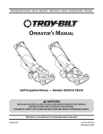
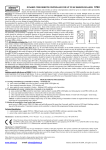
LIMITED WARRANTY
The Manufacturer warrants to the original consumer purchaser that this product as
manufactured is free from defects in materials and workmanship. For a period of
two (2) years from date of purchase by the original consumer purchaser, we will repair or replace, at our option, without charge for parts or labor incurred in replacing
parts, any part which we find to be defective due to materials or workmanship. This
Warranty is subject to the following limitations and exclusions.
1. This warranty does not apply to the engine. Please refer to the applicable
manufacturer's warranty on these items.
2. Transportation charges for the movement of any power equipment unit or attachment are the responsibility of the purchaser. Transportation charges for any
parts submitted for replacement under this warranty must be paid by the purchaser unless such return is requested by the manufacturer.
3. The Warranty period for any products used for rental or commercial purposes is
limited to 45 days from the date of original purchase.
4. This Warranty applies only to products which have been properly assembled,
adjusted, operated, and maintained in accordance with the instructions furnished.
This Warranty does not apply to any product which has been subjected to alteration, misuse, abuse, improper assembly or installation, delivery damage, or to
normal wear of the product.
5. Exclusions: Excluded from this Warranty are belts, rotating lines, rotating line
adapters, normal wear, normal adjustments, standard hardware and normal
maintenance.
6. In the event you have a claim under this Warranty, you must return the product to
an authorized service dealer.
Should you have any unanswered questions concerning this Warranty,
please contact:
In Canada contact:
HOP
Customer Service Department
1030 Stevens Creek Road
Augusta, GA 30907 USA
HOP
Customer Service Department
5855 Terry Fox Way
Mississauga, Ontario L5V 3E4
giving the model number, serial number and date of purchase of your product and
the name and address of the authorized dealer from whom it was purchased.
THIS WARRANTY DOES NOT APPLY TO INCIDENTAL OR CONSEQUENTIAL
DAMAGES AND ANY IMPLIED WARRANTIES ARE LIMITED TO THE SAME
TIME PERIODS STATED HEREIN FOR OUR EXPRESSED WARRANTIES.
REPAIR PARTS MANUAL
MODEL NUMBER PWT420
(MFG. ID. NO. 96171000203)
Wheeled Weed Trimmer
Some areas do not allow the limitation of consequential damages or limitations
of how long an implied Warranty may last, so the above limitations or exclusions
may not apply to you. This Warranty gives you specific legal rights, and you may
have other rights which vary from locale to locale.
This is a limited Warranty within the meaning of that term as defined in the Magnuson-Moss Act of 1975.
532 41 86-35 12.06.07 BY
Printed in U.S.A.
WEED TRIMMER - MODEL NUMBER PWT420 (96171000203)
PRODUCT NUMBER 961 71 00-02
SERVICE NOTES
30
19
34 35
1
28
20
18
33
11
21
16 10
12
26
27
9
15
23
15
8
9
26
24
23
24
27
22
2
38
36
2
3
37
7
SERVICE NOTES
WEED TRIMMER - MODEL NUMBER PWT420 (96171000203)
PRODUCT NUMBER 961 71 00-02
KEY
NO.
1
2
3
8
9
10
11
12
15
16
18
19
20
21
22
23
24
26
27
28
30
33
34
35
36
37
38
----
PART
NO.
---
532 15 04-06
532 17 94-66
532 18 67-54
532 15 00-78
532 18 67-55
532 17 09-80
532 19 19-38
532 17 97-51
532 19 47-88
532 06 64-26
532 17 69-83
532 41 72-38
532 15 87-55
532 18 67-56
532 15 00-78
532 05 21-60
532 17 02-58
532 40 91-48
532 18 16-99
532 41 25-05
532 13 20-04
532 12 52-03
532 75 06-34
532 85 10-84
532 85 02-63
532 85 10-74
532 18 74-78
532 18 74-79
532 41 86-35
DESCRIPTION
Engine, Briggs & Stratton,
Model Number 126T02
(Order parts from Engine Manufacturer)
Bolt, Engine Mounting 3/8-16
Pulley, Engine (Includes Setscrew, Key #4)
Handle, Lower
Screw, Hex Washer Head 5/16-18 x .75
Handle, Upper
Bolt, Handle
Knob, Handle
Handle Adjuster Assembly
Guide, Rope
Wire Tire
Control Bar
Throttle Control
Screw, Hex Washer Head
Axle Shaft Assembly
Screw, Hex Washer Head 5/16-18 x .75
Washer, Axle
Wheel, 14 x 2
Hex Flange Locknut 3/8-16
Drive Control Cable
Decal, Engine Cover
Nut
Bracket, Upstop
Screw, Thd. Roll. #10-24 x 5/8
Screw, Hex Head 3/8-24 x 1
Washer, Lock
Washer, Flat, Hardened
Operator’s Manual, European
Operator's Manual, Scandanivan
Repair Parts Manual, English
NOTE: All component dimensions given in U.S. inches. 1 inch = 25.4 mm
IMPORTANT: Use only Original Equipment Manufacturer (O.E.M.) replacement parts. Failure to do so could be
hazardous, damage your weed trimmer and void your warranty.
6
3
WEED TRIMMER - MODEL NUMBER PWT420 (96171000203)
PRODUCT NUMBER 961 71 00-02
51
52
20 44 47 21
14
43
1
17
4
40
15
8
12
5
41
6
45
7
10
13
11
9
19
22
23
24
25
26
27*
28
29
16
30*
18
3
32
34
27
31
33
46
37
27
38
2
39
36
4
35
WEED TRIMMER - MODEL NUMBER PWT420 (96171000203)
PRODUCT NUMBER 961 71 00-02
KEY
NO.
1
2
3
4
5
6
7
8
9
10
11
12
13
14
15
16
17
18
19
20
21
22
23
24
25
26
27
28
29
30
31
32
33
34
35
36
37
38
39
40
41
42
43
44
45
46
47
51
52
PART
NO.
532 18 67-60
532 18 22-19
532 17 37-15
532 18 54-76
532 18 67-51
532 16 60-42
532 17 37-16
532 75 15-92
532 16 60-43
532 16 08-29
532 15 55-52
532 17 37-17
532 17 47-19
532 40 91-49
532 17 38-11
532 18 02-68
532 05 78-08
532 17 88-48
532 19 95-74
532 17 83-90
532 14 97-46
873 61 06-00
532 85 02-63
819 12 12-14
532 18 03-40
532 17 25-51
532 17 45-49
532 17 25-20
532 18 67-52
532 17 45-43
532 17 45-81
532 17 39-73
532 17 25-19
532 18 03-38
532 18 22-17
532 17 25-16
532 17 45-80
532 17 25-23
532 18 03-34
532 18 03-33
532 17 40-29
532 18 74-58
532 17 40-42
532 18 66-00
532 18 67-53
817 06 04-08
532 18 22-05
532 18 90-06
532 17 88-48
DESCRIPTION
Chassis Assembly
Line, Trimmer .155 diameter x 18.75 long
Screw, Self-Tapping 5/16-18 x 1
V-Belt
Bracket, Idler
Pulley, Idler, V-Groove
Bolt, Hex Head 3/8-16 x 1.25
Locknut, Hex 3/8-16
Pulley, Idler, Flat
Bolt, Shoulder
Locknut 5/16-18
Spacer
Bolt, Shoulder
Locknut, Flange
Spring, Return
Deflector, Bottom
Screw 1/4-20 x 1/2
Screw #10-24 x 3/4
Belt Keeper
Cover, Chassis, Top
Screw #10-24 x 1-3/4
Nut, Hex 3/8-24 UNF
Washer, Lock 3/8
Washer, Flat 3/8
Pulley, Driven
Spacer, Pulley
Bearing
Jackshaft
Cover, Chassis, Bottom
Spindle Housing Assembly (* Includes Upper Bearing, Key No. 27)
Ring, Retaining, External, 17mm
Spring, Locking Plate
Locking Plate
Carrier Plate Assembly
Mow Ball Assembly (Includes Key Numbers 27, 37 and 38)
Cover, Bearing
Ring, Retaining, Internal, 40mm
Mow Ball
Bolt, Mow Ball
Spindle Assembly, Complete (Includes Key No. 22-28 and 30-39)
Spacer
Decal, Safety
Decal, Instruction
Decal, Chassis Cover
Belt Keeper, Bottom
Screw, Self-Tapping
Decal, Instruction
Deflector, Rear
Screw
NOTE: All component dimensions given in U.S. inches. 1 inch = 25.4 mm
IMPORTANT: Use only Original Equipment Manufacturer (O.E.M.) replacement parts. Failure to do so could be
hazardous, damage your weed trimmer and void your warranty.
5