1
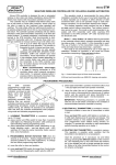
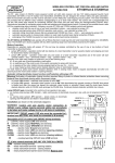
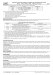
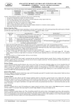
elmes electronic DYNAMIC CODE REMOTE CONTROLLER FOR UP TO SIX WINDOW ROLLERS ST6H The controller offers dynamic code wireless as well as wired operation control for up to six window rollers powered by electric AC tube motors with integral terminal switches. Operation. On command received from hand transmitter or wired wall switch one or more roller motors are started. Multiple motors are started sequentially with 0,5s time intervals (JP5 shorted) or with 0,13s intervals (JP5 opened). Moving rollers are stopped either by received next command or, by passage of programmed rotation time (programming procedures p.2). It is possible to program continuous AC motor powering time thus protecting the roller against manual opening while in roller closed end position. AC motor termination switch will power motor rotation and closes the roller on every attempt of manual lifting the closed roller. Recommended for operation with the ST6H controller are multi-channel Elmes CH8H and CH32H hand transmitters. One, two or four channel transmitters can also be used if necessary. Wired control of rollers connected to the controller is performed by up to 18 monostable dedicated wall switches with marked roller direction movement arrows. Some of the switches can be used to control all or group of rollers. Operation mode of the wall switches are user set by jumpers, as described in Table 1 of this instruction manual. Operation with hand transmitter. Example operation is explained with the use Elmes CH8H eight channel transmitter. The transmitter is equipped with four main control button switches as well as side sliding switch aimed for selection of operation function of the main buttons. Required functions must be first 1 2 5 6 selected by the side switch and confirmed by shining LED combination (see figure below) prior to using 7 8 3 4 the main buttons of the transmitter. General operation mode of the transmitter depends on settings made by jumper JP4, as follows; With JP4 shorted and button No 1 used while learning the transmitter to the ST6H controller, the 1..6 main button switches would independently control operation of up to 6 rollers in up-stop-down-stop-upstop.. mode while buttons 7 and 8 would control open and close movement of all six rollers. With JP4 shorted and button other than No 1 (e.g. 4) used while learning the transmitter to the ST6H controller, button No 3 and No 4 would control open and close movement of all six rollers respectively. Remaining switches will be inactive or may be used for other application. With JP4 opened. In this mode all buttons of the hand transmitter can operate according to programmed selected function, as described in Table 1. Example: in need to program button No 2 to open first three rollers and button No 4 to close the rollers jumpers JP1..JP3 should be set to OFFON-ON position, the rollers should be switched on and off by the use of wall switch No 7 (or respective controller inputs R3 and C2 shorted if the switch is not connected) and next, hand transmitter should be learned to the controller using transmitter’s button No 2 (see par. 1 of the programming procedures). Since then button No 2 would open rollers No 1,2,3. Similar steps should be taken with button No 4 of the hand transmitter using wall switch No 8 or shorting inputs R4 with C2. Remaining buttons can operate according to any other function offered in Table 1. Advice: to delete functions programmed to hand transmitter buttons, the transmitter must be deleted from controller’s memory. It is suggested to use deliberately two different buttons while at learning procedure of the transmitter to the controller (procedures 1b and 1c). Operation with Elmes CH32H hand transmitter. This transmitter generally incorporates four CH8H hand transmitters’ functions. The advantage of using this transmitter is that number of button combinations may be extended four fold and more window rollers can be controlled by single unit. Lighting control with the use of ST6H. Besides its standard application in window rollers environment, the ST6H controller may also be used to control operation of six lamps or light beams. To do so, controller inputs O and C of each channel must be shorted and continuous (bi-stable) relay output set on time must be programmed. The lamps can be switched on and off by the use of transmitter buttons or wall switches. PROGRAMMING PROCEDURES 1. Learning transmitter(s) to controller's memory – maximum 32: a) press control unit PRG switch for less than 2 seconds (PRG LED lights on), b) press required transmitter button - LED switches off, c) press again the same transmitter’s button – blinking LED confirms end of procedure. 2. Programming tube motor rotation time (4 seconds set as standard): a) press control unit PRG switch for more than 2 and less than 8 seconds (PRG LED lights on). Releasing the switch PRG LED sets off, b) press any hand transmitter button or wired wall switch to start motor rotation, c) after required motor rotation time has lapsed (max. 60 minutes) press the transmitter button or wired wall switch again - motor stops, d) after two seconds PRG LED starts blinking confirming end of the procedure. Advice! To obtain continuous (bi-stable) output relay set on time, double pressing of transmitter’s button is required with less than two seconds interval in programming step c) above. 3. Deleting all transmitters from control unit memory: press receiver's PRG switch (PRG LED lights on) and hold pressed for more than 8 seconds, until the receiver LED starts blinking confirming end of the procedure. Transmitter memory in the controller is cleared while programmed timings remain unchanged. Technical Specification • control panel mains supply 230VAC, 500mA fused, receiver band 433,92MHz with max operation range 200m, • power relay control outputs max 16A/250VAC, max number of hand transmitters: 32. Manufacturer: ELMES ELECTRONIC, 54-611 Wroclaw – PL, ul. Avicenny 2, tel. (+4871)784-59-61, fax (+4871)784-59-63 Elmes Electronic declares that the product has been manufactured and tested to comply with the following standards: EN 60950-1 :2001 electric safety, EN 301 489-1 V1.4.1 (2002-08) EMC for radio equipment, EN 301 489-3 V1.2.1 (2002-08) EMC for Short Range Devices, EN 300 220-3 V1.1.1 (2000-09) EMC and Radio Spectrum Matters. Manufacturer’s Limited Warranty: Elmes Electronic remote control sets carry one-year manufacturer’s warranty as from date of purchase. The warranty is limited to the replacement of faulty original parts or repair defects of improper manufacture. Damage, faulty use or improper handling by the user or installer as well as any changes in product’s hardware or software caused by the user violets the warranty and all due repair costs will be charged. Elmes Electronic shall not be responsible for any direct or indirect personal or material damage caused by its products failure to operate correctly. Elmes Electronic reserves the right to change product specification without prior notice. KEELOQ® is a registered trademark of Microchip Technology Inc., USA. www.elmes.pl e-mail: [email protected] Elmes Elektronik 09.2006. All rights reserved. Table 1. Presentation of wall switch control modes depending on JP1, JP2, JP3 presets. The numbers in column one represent respective wall switches connected to inputs R1..4 and C1..4 as shown on connection schematic diagram below. Prior to firm installation of the controller one of eight possible operation modes should be selected. If individual control of every window roller in up-stop-down-stop-up.. way is at priority then operation mode 1..3 should be selected. If two button switches are installed then operation mode is 4..6. Mode 7 and 8 are used if selected window rollers are used in groups of 2, 3 or 4 units (e.g. with extremely wide window display facade). In the next step, roller groups must be defined. With the groups definition ready, operation mode should be selected in the bottom end raw of Table 1. Switch number 1 2 3 4 5 6 7 8 9 10 11 12 13 14 15 16 Groups * Mode 1 JP1-JP2-JP3 ON-ON-ON 1 - ↑↓ 2 - ↑↓ 3 - ↑↓ 4 - ↑↓ 5 - ↑↓ 6 - ↑↓ 1,2 - ↑ 1,2 - ↓ 3,4 - ↑ 3,4 - ↓ 5,6 - ↑ 5,6 - ↓ 1,2,3,4 - ↑ 1,2,3,4 - ↓ 1,2,3,4,5,6 - ↑ 1,2,3,4,5,6 - ↓ 2-2-2, 4-2, 6 Mode 2 JP1-JP2-JP3 OFF-ON-ON 1 - ↑↓ 2 - ↑↓ 3 - ↑↓ 4 - ↑↓ 5 - ↑↓ 6 - ↑↓ 1,2,3 - ↑ 1,2,3 - ↓ 4,5,6 - ↑ 4,5,6 - ↓ 5,6 - ↑ 5,6 - ↓ 1,2,3,4 - ↑ 1,2,3,4 - ↓ 1,2,3,4,5,6 - ↑ 1,2,3,4,5,6 - ↓ 3-3, 3-1-2, 4-2, 6 Mode 3 JP1-JP2-JP3 ON-OFF-ON 1 - ↑↓ 2 - ↑↓ 3 - ↑↓ 4 - ↑↓ 5 - ↑↓ 6 - ↑↓ 1,2,3 - ↑↓ 4,5,6 - ↑↓ 1,2 - ↑↓ 3,4 - ↑↓ 5,6 - ↑↓ 1,2,3,4 - ↑↓ 1,2,3,4,5 - ↑↓ 1,2,3,4,5,6-↑↓ 1,2,3,4,5,6 - ↑ 1,2,3,4,5,6 - ↓ 3-3, 2-2-2, 4-2 3-1-2, 5-1, 6 Mode 4 JP1-JP2-JP3 OFF-OFF-ON 1-↑ 1-↓ 2-↑ 2-↓ 3-↑ 3-↓ 4-↑ 4-↓ 5-↑ 5-↓ 6-↑ 6-↓ 1,2,3 - ↑ 1,2,3 - ↓ 4,5,6 - ↑ 4,5,6 - ↓ 3-3 3-1-1-1 Mode 5 JP1-JP2-JP3 ON-ON-OFF 1-↑ 1-↓ 2-↑ 2-↓ 3-↑ 3-↓ 4-↑ 4-↓ 5-↑ 5-↓ 6-↑ 6-↓ 1,2,3,4 - ↑ 1,2,3,4 - ↓ 5,6 - ↑ 5,6 - ↓ 4-2, 4-1-1 2-1-1-1-1 Mode 6 JP1-JP2-JP3 OFF-ON-OFF 1-↑ 1-↓ 2-↑ 2-↓ 3-↑ 3-↓ 4-↑ 4-↓ 5-↑ 5-↓ 6-↑ 6-↓ 1,2,3 - ↑ 1,2,3 - ↓ 1,2,3,4,5,6 - ↑ 1,2,3,4,5,6 - ↓ 3-1-1-1 6 Mode 7 JP1-JP2-JP3 ON-OFF-OFF 1-↑ 1-↓ 2-↑ 2-↓ 3-↑ 3-↓ 4-↑ 4-↓ 1,2 - ↑ 1,2 - ↓ 5,6 - ↑ 5,6 - ↓ 4,5,6 - ↑ 4,5,6 - ↓ 1,2,3,4,5,6 - ↑ 1,2,3,4,5,6 - ↓ 2-2-1-1, 2-1-3 2-1-1-1-1, 3-1-1-1, 6 Mode 8 JP1-JP2-JP3 OFF-OFF-OFF 1-↑ 1-↓ 2-↑ 2-↓ 1,2 - ↑ 1,2 - ↓ 3,4 - ↑ 3,4 - ↓ 5,6 - ↑ 5,6 - ↓ 3,4,5,6 - ↑ 3,4,5,6 - ↓ 2,3,4,5,6 - ↑ 2,3,4,5,6 - ↓ 1,2,3,4,5,6 - ↑ 1,2,3,4,5,6 - ↓ 2-2-2, 4-2 4-1-1, 5-1, 6 * the last raw of the Table shows up possible control solutions in respective modes, e.g. 4-2 meaning that with the use of one double button switch a group of 4 rollers can be controlled while next double switch would control group of two rollers. 1,2,3,4,5,6 – roller numbers; 1,2...15,16 – numbers of connected wall switches, ↑↓ - roller operation mode: up-stop-down-stop-up-stop.. ↑ - roller operation mode: up-stop-up...; ↓ - roller operation mode: down-stop-down… Controlling more than 6 rollers. Possible with the use of more than one ST6H control panels. All rollers close or open function requires connection of wall switch to OP and CL inputs of all control panels. System clock connection. System clock can be connected to the ST6H panel through dedicated input D/N. Connecting the D/N to COM would close all opened rollers while disconnecting D/N from COM would open closed rollers. D/N inputs of many controllers can be connected together so that single system clock would control all rollers. Installation schematic diagram: 5 9 13 2 6 10 14 3 7 11 15 4 8 12 16 R1 R2 R3 R4 C1 C2 LIVE NEUTRAL L N C3 C4 COM GROUND D/N OP . . MOTOR 6 CL N C O 230VAC supply LIVE wire must be connected to L terminal and NEUTRAL wire must be connected to N terminal. N C O IMPORTANT! Control board MOTOR 1 . . ~230V Installation: The ST6H control panel is powered from 230VAC mains line. For safety reasons installation can be made with mains cable DISCONNECTED. The panel with integral radio receiver may be installed indoor only and far from harsh environmental conditions like high or low temperatures, high humidity or radio and electric interference. Antenna wire of the ST6H controller should be downwards directed and cannot be fixed or glued to wall. Complete connection diagram with mains cable, AC tube motors and external wall switches is shown on installation schematic diagram. 1 GND ANT O - opening C - closing WARNING! Control unit and electric AC motors are 230VAC mains supplied and their installation requires personal safety procedures to be taken. Installation MUST NOT be made with supply cable connected to mains! Prior to installation disconnect mains supply!