1
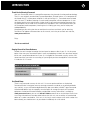
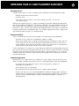
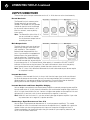
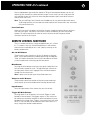
IMPORTANT SAFETY INSTRUCTIONS
The lightning flash with the arrowhead symbol within an equilateral triangle is intended to alert the user
to the presence of “dangerous voltage” inside the product that may constitute a risk of electric shock.
The exclamation point within an equilateral triangle is intended to alert the user to the presence
of important operating and maintenance instructions in the literature accompanying the product.
TO REDUCE THE RISK OF ELECTRIC SHOCK, DO NOT REMOVE COVER. NO USER-SERVICEABLE
PARTS INSIDE. REFER SERVICING TO QUALIFIED SERVICE PERSONNEL
1.
Read Instructions — Read all the safety and operating instructions before operating this product.
2.
Retain Instructions — Retain safety and operating instructions for future reference.
3.
Heed Warnings — Adhere to all warnings on the product and in the operating instructions.
4.
Follow Instructions — Follow all operating and use instructions.
5.
Cleaning — Unplug this product from the wall outlet before cleaning. Use a damp cloth for cleaning.
Clean the outside of the product only.
6.
Attachments — Do not use attachments that are not recommended by the product manufacturer;
they may be hazardous.
7.
Water and Moisture — Do not use this product near water.
8.
Accessories — Do not place this product on an unstable cart or stand. The product may fall, causing
bodily injury and damage to the product. A product and cart combination should be moved with care.
Quick stops, excessive force, and uneven surfaces may cause the product and cart to overturn.
9.
Ventilation — Slots and openings in the cabinet are provided for ventilation to ensure reliable operation of
the product and to protect it from overheating. These openings must not be blocked or covered. This product
should not be placed in a built-in installation such as a bookcase or rack unless proper ventilation is provided.
10. Power Sources — Operate this product only from the type of power source indicated on the label.
If you are not sure of the type of power supply to your home, consult your dealer or local power
company. This product is equipped with a three-prong grounding plug. This plug will only fit into a
grounding power outlet. If you are unable to insert the plug into the outlet, contact your electrician
to replace your obsolete outlet. Do not defeat the safety purpose of the grounding plug.
11. Power Cord Protection — Power supply cords should be routed so that they are not likely to be
walked on or pinched by items placed upon or against them.
12. Lightning — Unplug the unit from the wall outlet for added protection during a lightning storm
and when it is left unattended and unused for long periods of time. This will prevent damage to the
product due to lightning and power line surges.
13. Overloading — Do not overload wall outlets or extension cords. This can result in a fire or electric shock.
14. Inserting Objects into Unit — Never push objects of any kind into this product through any openings;
they may touch dangerous voltage points or short out parts that could result in fire or electric shock.
15. Servicing — Do not attempt to repair or service this product yourself. Opening or removing covers may
expose you to dangerous voltage and other hazards. Refer all servicing to qualified service personnel.
16. Damage Requiring Service — Unplug this product from the wall outlet and refer servicing to qualified
service personnel under the following conditions: a) If the power-supply cord or plug is damaged.
b) If liquid has been spilled into the product. c) If the product has been exposed to rain or water. d)
If the product does not operate normally by following the operating instructions. e) If the product has
been dropped or damaged in any way. f) If the product exhibits a distinct change in performance.
17. Replacement Parts — When replacement parts are required, be sure the service technician has used
replacement parts specified by the manufacturer. Unauthorized substitutions may result in fire, electric
shock, and other hazards.
18. Safety Check — Upon completion of any service or repairs to this product, ask the service technician
to perform safety checks to determine that the product is in proper operating condition.
19. Wall or Ceiling Mounting — Mount the product to a wall or ceiling only as recommended.
20. Heat — The product should be situated away from heat sources such as radiators, heat registers,
stoves, and other products (including amplifiers) that produce heat.
www.parasound.com
INTRODUCTION
3
Thank You for Choosing Parasound
Your new Parasound® Halo JC 2 preamplifier represents the pinnacle of analog audio technology.
The JC 2 was originally conceived by Parasound president, Richard Schram, as a companion for
the famed Halo JC 1 mono power amplifier. In the spirit of the JC 1, Parasound commissioned
John Curl and CTC builders to design a two channel preamplifier without compromise. It uses
the highest quality parts and achieves a higher level of sonic and measured performance than
any preamplifier we’ve made since Parasound was founded in 1981. We’re proud to offer you
this exceptional audio component, knowing that it will bring you many years of enjoyment
and dependability.
We appreciate your taking the time to read these instructions and thank you for selecting
Parasound. For updates and corrections to this manual, we invite you to check our web site,
www.parasound.com
Enjoy.
The Parasound Staff
Keeping Records for Future Reference
Record the serial number located on the back panel or bottom side of your JC 2 in the space
below. Also note your Parasound Dealer’s name and telephone number. Your purchase receipt/
bill of sale is required to determine if your JC 2 is eligible for Parasound warranty service. We
recommend that you make an extra copy of your original purchase receipt/bill of sale and store
it inside the JC 2’s carton.
OWNERSHIP REFERENCE INFORMATION
Parasound JC 2 Preamplifier Serial #:
Parasound Dealer:
Dealer Phone Number:
(
)
-
Date of Purchase:
/
/
You Should Know
There is no Parasound warranty for this unit if it was not purchased from an Authorized
Parasound Dealer. Investigate warranty coverage statements made by an unauthorized dealer
very carefully, as you will need to depend entirely upon your dealer, and NOT upon Parasound.
Unauthorized dealers lack the capability to make repairs or arrange for repairs of Parasound
equipment. Authorized Parasound Dealers and detailed warranty information is available at
www.parasound.com or you can call 415-397-7100 between 8:30 am and 4:30 pm Pacific time.
A missing or altered serial number could indicate that this unit was re-sold by an unauthorized
dealer or is stolen merchandise. If this unit is missing its serial number or the serial number has
been altered, you should return it to your dealer immediately for a full refund.
4
TABLE OF CONTENTS
Important Safety Instructions .
Introduction
. . . . . . . . . . . . . . . . . . . . . . . . . . . . . . . . . . . . . . .
2
. . . . . . . . . . . . . . . . . . . . . . . . . . . . . . . . . . . . . . . . . . . . . . . . . . .
3
Unpacking and Placement Guidelines .
Rack Mounting
. . . . . . . . . . . . . . . . . . . . . . . . . . . . . . . . .
5
. . . . . . . . . . . . . . . . . . . . . . . . . . . . . . . . . . . . . . . . . . . . . . . . .
6
115 – 230v AC Selector Switch .
Connecting your JC 2
Operating your JC 2
. . . . . . . . . . . . . . . . . . . . . . . . . . . . . . . . . . . . . .
6
. . . . . . . . . . . . . . . . . . . . . . . . . . . . . . . . . . . . . . . . . . . . .
7
. . . . . . . . . . . . . . . . . . . . . . . . . . . . . . . . . . . . . . . . . . . . .
Remote Control Functions
Design Overview .
. . . . . . . . . . . . . . . . . . . . . . . . . . . . . . . . . . . . . . . . .
11
. . . . . . . . . . . . . . . . . . . . . . . . . . . . . . . . . . . . . . . . . . . . . .
12
Frequently Asked Questions.
. . . . . . . . . . . . . . . . . . . . . . . . . . . . . . . . . . . . . . .
If You Require Assistance or Warranty Repair .
Specifications .
10
13
. . . . . . . . . . . . . . . . . . . . . . . . . . .
14
. . . . . . . . . . . . . . . . . . . . . . . . . . . . . . . . . . . . . . . . . . . . . . . .
15
UNPACKING YOUR JC 2 AND PLACEMENT GUIDELINES
Unpacking Your JC 2
Carefully remove your JC 2 from its shipping carton and locate all the enclosed accessories:
•
Remote control and two AAA batteries
•
AC power cord
•
Four trigger wires, two with 2.5 mm sub-mini plugs, two with a 2.5 mm and
a 3.5 mm mini plug
While you are unpacking your JC 2, inspect it thoroughly for possible shipping damage and tell
your Parasound dealer immediately if you find any. If possible, save and store both the inner and
outer cartons and—most especially—the foam packing inserts, to protect the JC 2 if you have
to move it or ship it. You may wish to flatten the cardboard cartons to save room in storage after
cutting the taped seams on the bottom flaps. This would be a good time to make a copy of your
sales receipt to store with the JC 2’s original packing.
Placement Guidelines
The JC 2 will be easier to use and will last longer if you follow these simple guidelines:
•
Place the JC 2 on a shelf that will adequately support its weight.
•
Unless you’ll control the JC 2 through a remote infrared sensor/repeater system, put it on
a shelf where you can aim the remote control handset directly at the JC 2. (If you use a
remote repeater sensor, be sure the remote’s signals can’t reach the JC 2’s front panel IR
sensor, otherwise the remote control will not function properly).
If you’re installing the JC 2 yourself, use input and output cables that are long enough to leave at
least two feet of slack; that will enable you to pull the JC 2 out of a cabinet to check or to change
connections without inadvertently disconnecting cables. If you’re putting the JC 2 in a cabinet,
it needs a space that’s at least 22 inches wide so you’ll be able to turn it around for access to its
rear panel connections.
Ventilation Requirements
Because the JC 2 is a high current class A design it is always slightly warm to the touch, even
when in standby. To reduce the chance of your JC 2 overheating please follow these guidelines:
•
Install your JC 2 away from heat sources such as heating ducts, radiators, or
heat-producing components.
•
Always position the JC 2 horizontally.
•
We recommend that you do not place the JC 2 above a power amplifier.
•
Do not install the JC 2 in an unventilated equipment cabinet or compartment. Pockets of
stagnant hot air can build up even in cabinets with open front and back sides. A ventilation
fan such as the Parasound Zbreeze is highly recommended to prevent “hot spots” in
confined spaces.
5
6
UNPACKING YOUR JC 2 AND PLACEMENT GUIDELINES
Rack Mounting Your Parasound JC 2
With its four feet removed, the JC 2’s front panel height occupies three rack spaces (5 1/4” or
133 mm. (A single standard rack space occupies 1 3/4” vertical space.) For mounting in a standard
19” equipment rack, you must use the Parasound HRA 3 rack mount kit (purchased separately).
The HRA 3 includes four bolts and eight plastic washers with raised “shoulders.”
Slide one washer onto each
mounting bolt with its raised
shoulder pointing toward
the panel hole.
Carefully insert the bolt
through the hole and slide
the other washer on the
bolt with its raised shoulder
facing the rear side of the
panel. The washers will
sandwich the JC 2 panel
and the four mounting bolts
to prevent metal-to-metal
contact between the Model
JC 2 chassis, the equipment
rack, and the other components mounted in the rack.
Note: Tighten each bolt just enough to keep the unit secure in the rack to avoid deforming the
shoulder washers.
Eliminating metal-to-metal contact reduces the likelihood of creating a ground loop that might
introduce hum into your system.
A custom rack-mount shelf for the JC 2 is available from Middle Atlantic Products, Inc.®,
http://www.middleatlantic.com/
115v – 230v AC Voltage Selector Switch
Note: The unit may be seriously damaged if this switch is set incorrectly.
Prior to plugging your JC 2 into an AC power source, check the position of the 115v/230v
switch on the JC 2’s rear panel and do not depend on the 115v or 230v markings on the carton.
This switch is found on the rear panel near the AC (“mains”)
receptacle. The 115V position of this switch is correct for North
America; most other countries require setting it to 230V. Make sure
the 115/230V switch is set for the correct AC line (mains) voltage
before you plug in the JC 2’s power cord.
CONNECTING YOUR JC 2
Always disconnect the AC cord to your JC 2 and power amplifier(s) before making or changing
any input, output or trigger wire connections. Inserting or removing an input or output cable
while the JC 2 or power amplifiers are turned on can result in a blast of sound that can damage
your loudspeakers. Make sure there is no strain or tension on any cables that could cause
them to pull loose.
INPUT CONNECTIONS
There are a total of six line level input jacks on your
JC 2. Input 1 and Input 2 include both Balanced XLR
and Unbalanced RCA connections.
Unbalanced RCA Input Jacks
All of the six unbalanced RCA inputs have the same
input sensitivity and impedance. These inputs are
compatible with any typical analog line level source.
When using the In 1 or In 2 unbalanced RCA input
connections, set the input’s corresponding Balanced/
Unbalanced selector switch to Unbalanced.
Balanced XLR Input Jacks
Use these inputs to connect any source components
with balanced outputs. A balanced line provides
superior hum and noise cancellation, especially for
long cable runs. Many serious listeners also prefer
the sonic characteristics of balanced interconnects
because the lower inherent noise floor contributes
to a more defined and spacious soundstage. When
using the balanced XLR input connections, set the
input’s corresponding Balanced/Unbalanced selector
switch to Balanced.
7
8
CONNECTING YOUR JC 2 continued
OUTPUT CONNECTIONS
There are four pairs of output connections on the JC 2. All of them are active simultaneously.
Record Out Jacks
The Record Out jacks connect to the
Record Input jacks on your audio
recorder. The Record Out jacks provide
fixed level signals that are unaffected
by the master volume control, L or R
level trim controls, mute or polarity
invert select.
Note: The Record Out jacks of the JC 2
are not switched as a monitor
for simultaneous comparisons of
recording to source.
Main Output Jacks
The Main Output Jacks are the primary
outputs that connect to the inputs on
your amplifier(s). There are both
balanced and unbalanced Main Out
jacks. If your amplifier is equipped with
balanced inputs we recommend this
type of connection. The polarity of the
Main Outputs is the same as the input,
but can be inverted 180° by pressing the
Invert button on the JC 2’s remote control. When polarity is inverted the POLARITY INVERT
indicator will illuminate on the front panel. For more information on when to use the polarity
invert feature please see the Frequently Asked Questions section of this manual.
Note: The JC 2 uses a fully differential balanced circuit and its balanced outputs do not require
or use phase inverters.
Inverted Out Jacks
The polarity at the Inverted Out jacks is always 180° from the input signal, and is not affected
by the Invert button on the remote. You may use the inverted output jacks to maintain correct
absolute polarity if your power amplifier(s) invert polarity. For more information on absolute
polarity please see the Frequently Asked Questions section of this manual.
Inverted Out Jacks and Power Amplifier Bridging
You can bridge a conventional two channel power amplifier to mono by connecting one amplifier
input channel to the JC 2’s left channel Inverted Out jack and the other amplifier input channel to
the JC 2’s right channel Main Out jack. Connect a single mono speaker to the amplifier’s left and
right positive (+) terminals, with no wires connected to its negative (–) terminals.
Note: While this won’t hurt the JC 2, you can seriously damage the power amplifier if you make
any connections to its negative (–) speaker terminals.
Connecting a Signal Processor to Your JC 2
You can patch a signal processor between the JC 2 and your power amplifier(s). This would
include devices such as an electronic crossover or the equalizer that is supplied with a particular
speaker. Make sure that the signal processor’s input can accept the full output of the JC 2
without overloading. You should also adjust the gain controls of your amplifier, processor, and
the JC 2 for the lowest noise level.
CONNECTING YOUR JC 2 continued
OTHER CONNECTIONS
12V Trigger Out
There are four 12 volt trigger outputs. These can be used to turn on power
amplifiers and other equipment that are equipped with automatic turn-on inputs.
Two of the 12 volt trigger output jacks labeled 1 and 2 are live whenever the JC 2
is turned on. The jacks labeled 3 and 4 are activated when you press the Trigger On
button on the remote control. Triggers 3 and 4 are always off when the JC 2
is powered off.
Connect the JC 2 12V output jack to the triggered component’s trigger input jack
using the provided trigger wire with the 2.5 mm sub-mini plugs.
Note: Most Parasound Power Amplifiers are equipped with a 2.5mm 12V trigger input jack. The
trigger voltage source is DC and the trigger plug tip is + (positive) and its sleeve – (negative).
The JC 2 combined trigger output maximum current capability is 150mA total.
External Remote Input
Your JC 2 is compatible with most popular infrared repeater systems for remote
control operation from another room or when the JC 2 is installed in a cabinet
where its remote handset signals cannot reach its front panel remote control
sensor. The External Remote Input connector is a standard 1/8” (3.5 mm) “mini”
jack. The center conductor (plug tip) is for + and the outer conductor (plug sleeve)
is for – . Your Authorized Parasound dealer or custom installer can recommend a
compatible IR repeater system.
RS-232 Serial Port
This 9-pin female DB9 connector is a full-duplex serial port. This permits
the JC 2 to communicate in two directions with home automation and
control systems such as Crestron, AMX, Control4, Niles and Elan. When
the JC 2 is connected to such a device, it can be controlled and its status
monitored from keypads or touch-screen panels throughout your house. The capabilities of such
connections, and the programming and interfacing needed will depend on the automation system
you select; consult your Parasound dealer or custom installer for more information regarding
interfacing an external control system to your JC 2. The complete RS-232 protocol can be found at:
www.parasound.com.
AC Power
The IEC standard AC cord supplied with your JC 2 is an audiophile-grade
component. Please connect it directly to an AC wall outlet that is always
“live.” If possible, plug your JC 2 into the same AC outlet that your
accompanying audio components (particularly your source components
and power amplifiers) are plugged into. If different AC outlets are used
the ground potential may be higher or lower between the outlets,
resulting in audible hum.
9
10
OPERATING YOUR JC 2
Before turning the JC 2 on, recheck all your connections and turn down the volume control to
avoid any unpleasant “blasts” that could damage your speakers.
Turn On Delay
The first time you turn on your JC 2 after connecting its AC power it will automatically mute
for 45 seconds with its Mute indicator flashing red. This time allows the JC 2 to warm up and
stabilize its circuits so you don’t hear any turn-on transients. After the first turn-on, its turn on
delay will be only 4-5 seconds.
Note: Your JC 2 will also mute for 45 seconds the first time you turn it on after its AC power was
interrupted or disconnected.
FRONT PANEL CONTROLS
On-Off Button
Push once to turn on. Push again to turn off. The Mute LED will flash for 4-5 seconds whiles its
circuits stabilize. After the circuits stabilize the muting will disengage.
Input Select Button
The INPUT button selects the 6 inputs and a blue LED indicates which input is selected. You will
select the next input each time you press it. Input 1 comes after input 6.
Volume Control
Your JC 2 employs a precision close-tracking four gang potentiometer to adjust master volume
level. Adjust your power amplifier gain controls (if it has them) so that your JC 2 master volume
knob’s indicator is between 11 o’clock and 1 o’clock for your most typical listening level. This is its
“sweet spot” where the control’s left/right channel tracking is closest and its distortion is lowest.
Note: The JC 2 has a maximum gain of 14 dB, which is suitable for most power amplifiers, and
for all Parasound power amplifier models, including the JC 1.
Left and Right Level Controls
Adjusting left and right channel balance is helpful to compensate for speaker placement,
room acoustics or if your power amplifier’s gain isn’t identical for both channels.
The JC 2 does not have a conventional balance control knob because a single part would
compromise crosstalk and impair the JC 2’s precise sound-stage reproduction. Further, in its
center position a balance control potentiometer’s wipers remain in the audio circuit. There are
no balance control potentiometers which meet Parasound’s quality standards for the JC 2.
OPERATING YOUR JC 2 continued
We use independent high-resolution Japanese TKD gain control potentiometers to trim the
volume of each channel for a balanced sonic image. In most cases you will simply leave the
Left and Right knobs fully clockwise where the potentiometer wipers make direct contacts
and are out of the circuit.
Note: The Left and Right Level Controls are intended only for very precise adjustment over a
10 dB range and they will not reduce channel output levels to zero when they are turned
fully counter-clockwise.
Invert Indicator
When this illuminates, the polarity of the Main Outputs are being inverted 180° out of phase
from the input signal. The polarity invert feature can be turned on or off from the remote
handset. For more information on when to use this feature see the Frequently Asked
Questions section of this manual.
REMOTE CONTROL FUNCTIONS
The JC 2 remote control has a range of approximately 20 – 25 feet
(6 – 7.5 meters). Use only AAA alkaline batteries in the handset
and insert them according to the + and – polarity markings in the
battery compartment.
On and Off Buttons
These have the same function as the On-Off button on the front
panel. These separate buttons enable programming unambiguous
“hard” off and on commands into a system controller or to create
a macro sequence for a learning-type remote control.
Mute Button
Pressing the Mute button once mutes the signal at both Main Out
jacks and the Inverted Out jacks. The red Mute light will flash on
the front panel while mute is engaged. Press the Mute button a
second time to cancel mute.
Note: It does not mute the signal at the Record out jacks.
Volume ▲ and ▼ Buttons
These buttons control the rotation of the front panel motorized
Level control, to increase and decrease listening volume levels.
Input Buttons
Press the input button of the source that you wish to hear.
Trigger Off & On Buttons
Pressing these On or Off buttons will activate Triggers 3 and 4
located on the rear panel. The triggers output 12 volts which can
be used to turn on power amplifiers or other components that are
equipped with a trigger input. Triggers 3 and 4 are always off when
the JC 2 is off, but they can be turned on or off when the JC 2 is
on by using these remote handset buttons.
11
12
OPERATING YOUR JC 2 continued/DESIGN OVERVIEW
Polarity Normal & Invert Buttons
The polarity (or phase) of the Main Outputs is the same as the input unless you press the Invert
button to invert the polarity of the Main Outputs 180° relative to the input signal. Pressing the
Normal button restores normal 0° polarity of the Main Outputs.
For more information on when to invert polarity, please see the Frequently Asked Questions on
page 13 of this manual.
Parasound Tuner Buttons
These buttons will control Parasound Halo Tuners such as the T 3. They select FM or AM band
and allow you to scroll through its presets.
“Burning-in” Your JC 2
Like many other great high end preamplifiers, your JC 2 should operate for at least 72 hours
with music playing (any volume level is ok) after it is first turned on before it will sound its best.
This gives various internal components and wiring a chance to “form” their optimum electron
pathways so they can pass complex musical information with greater definition, smoothness and
transparency. Although your JC 2 will sound spectacular when you first turn it on, you will come
to appreciate it even more as your listening hours accumulate. You’ll discover additional musical
details you may not have known were present.
Maintaining Your JC 2
Your JC 2 requires no periodic maintenance and has no user serviceable parts inside. To
avoid risk of electric shock do not remove the top cover. To keep it clean use only a soft cloth
moistened with a few drops of clear water or Windex. Never use any solvents or abrasives.
The remote control handset batteries should be removed whenever it will be unused for an
extended period. Remove the battery cover annually to inspect and remove leaking batteries.
DESIGN OVERVIEW
John Curl’s symmetrical circuits are well-respected and give the listener the best chance to
experience the full emotional content of the source. In the JC 2 the physical implementation
of the circuits closely follows the circuit topology and the layout is as literal as possible,
commensurate with isolation of disparate or out-of-phase signals. All component parts are
oriented for minimum interaction. The high current, low impedance audio power supply is
larger than many amplifiers and carefully integrated with the signal boards. The resulting
musical output blooms with both absolute musical authority and clarity.
The chassis and PCB layout of the JC 2 are uncompromised in their pursuit of the highest
design goals for a preamplifier. The shortest signal path is achieved by placing the master
volume control and individual channel level potentiometers and high quality gold-plated input
select relays right where the input circuitry is located to eliminate the need for long wires and
traces. Each channel is on a separate PCB. The preservation of low level signals is achieved by
the separation of critical audio signals from non-audio circuits. The audio power supply, control
power supply and control circuits also have dedicated PCBs. To prevent the possibility of
radiated noise getting into an audio circuit the power supplies and control functions are further
isolated from each other by two 3/8 inch thick aluminum partitions that are the full height of the
chassis and run side-to-side and front-to-back. The entire signal path is embedded on circuit
boards in a continuous ground plane or carried in professional-grade Canare® shielded wires.
Even within the audio circuit’s power supply section, AC power is isolated from regulated
power by placing the power transformer high in the chassis on one of the aluminum partitions.
The power transformer is an R-core type, which has the advantage of a toroid transformer for
minimizing radiated hum but is superior at preventing noise carried on the AC power line from
passing into its secondary windings. Ground return paths are low resistance, with substantial
planes and thick wires, and sequenced precisely. Non-audio control circuitry, LEDs, relay coils
and the motor for the master volume control are powered by a separate power supply whose
transformer has a separate ground return. The resulting extremely low noise levels enable
musical nuances to overlay an utterly silent background.
FREQUENTLY ASKED QUESTIONS
Why is there no sound from the speakers?
- Check that AC is live and the “P” badge and an input LED are illuminated.
- Check that input and output cables are secure at both ends.
- Make sure your JC 2 is switched to the correct input.
What could cause the remote to not work?
- Remote’s batteries are weak or dead. Earth911.org shows battery recycling options.
- Insure that the front panel IR receiver is not obscured or exposed to direct sunlight or to an LCD
or a plasma TV screen.
- IR signals might be being received by both the rear panel input and the front panel sensor.
Ensure that the IR signals are only reaching one of the two.
I can hear a background hum from the speakers
- Move audio cables and AC cords away from each other (while power is off).
- Try to route audio cables and AC cords perpendicular to each other (while power is off).
- Make sure insulating shoulder washers are used if unit is rack mounted.
- Reverse the direction of the other components’ AC plugs, one-by-one (while power is off).
- Ensure that the power amps and the JC 2 are plugged into the same AC outlet
The sound is distorted and weak
- Make sure the gain of the power amp is not set too low.
- Are you trying to use the JC 2 with a turntable? It does not have a built-in phono preamplifier
stage. You will need a phono preamp such as the Parasound Zphono. Visit www.parasound.com.
- Make sure the stereo power amp’s stereo/mono switch is set to stereo.
Why does the red Mute Indicator flash every time I turn my JC 2 on?
The first time you turn on your JC 2 after its AC power was interrupted or disconnected it will
automatically mute for 45 seconds with its Mute indicator flashing red. This time allows the JC 2
to warm up and stabilize its circuits so you don’t hear any turn-on transients. After the first
turn-on its turn on delay will be only 4-5 seconds.
When should I use the Polarity Invert feature?
Correct absolute polarity insures that loudspeaker cone or diaphragm movement in (negative
pressure) and out (positive pressure) is consistent with the original recording. While correct
absolute polarity may not be noticeable in many recordings, you will detect a marked audible
improvement in very well-recorded performances. Contact the manufacturer of your power
amplifier(s) and source components if you are uncertain if they maintain correct polarity. If your
amplifiers or other equipment do invert the polarity you will want to use the Inverted Outputs.
Please note that Parasound amplifiers do not invert the polarity. You may also find that some
recordings sound better when inverting the polarity. In this case you can select the polarity that
sounds best using the remote handset.
Should I use Balanced or Unbalanced connections?
Recording and broadcast studios use balanced connections almost exclusively because of
balanced lines’ inherent ability to reject noise and hum, even when components are far apart and
connected by long cables. Certain high-quality preamplifiers, amplifiers, and surround controllers
built for residential use also include balanced connections with XLR jacks for the same reasons.
The JC 2’s balanced outputs enable you to take full advantage of the inherent noise-rejection
capability and superior sound quality of Parasound Halo power amplifiers, especially when the
power amplifiers are located near the speakers, far from the JC 2. The balanced inputs on the
13
14
FREQUENTLY ASKED QUESTIONS continued/ WARRANTY
JC 2 also insure the best possible analog connection to source components which are equipped
with balanced outputs.
We generally recommend balanced connections if your power amplifiers or source equipment
are located more than 10 feet from your JC 2. Many serious listeners prefer the sonic
characteristics of balanced connections because their lower inherent noise floor contributes
to a more defined and spacious soundstage. When using the balanced XLR input connections,
set the input’s corresponding Balanced/Unbalanced selector switch to the Balanced position.
Where should I set the Left and Right gain controls?
In most cases you will simply leave the Left and Right knobs fully clockwise where they are
completely out of the audio circuit. If you do need to compensate for speaker placement or room
acoustics lower one of the controls until the volume level of the left and right speakers are equal.
WARRANTY REPAIR
Call your Parasound dealer first. If the dealer can’t help you with your problem we encourage you
to call Parasound’s Technical Service Department, toll-free at 1-866-770-8324, Monday – Friday,
8am – 4pm Pacific time. We can suggest other diagnostic tests you can easily perform.
If we determine that your JC 2 should be returned to Parasound or an Authorized Parasound
Warranty Center for inspection and possible servicing, we will provide the location of a warranty
center near you or shipping instructions for the unit’s return to Parasound.
Before You Return Any Unit to Parasound for Service
Before you send your unit to Parasound, you will need to obtain a specific Return Authorization
(RA) number and shipping instructions from Parasound’s Technical Department. The RA number
must be clearly marked on the outer carton. Use the original factory packing materials and
arrange adequate insurance to cover its value. You must include a copy of your purchase receipt,
since this document establishes the validity of this unit’s warranty. Warranty repairs are only
performed by Parasound or Parasound Authorized warranty centers when your purchase receipt
is from a Parasound Authorized Dealer or Parasound Authorized Reseller.
Units Will Be Refused by Parasound Under the Following Conditions:
1. Unit was sent without the Parasound-assigned RA number marked on the carton.
2. Unit was sent in an unsuitable shipping carton, likely to have been damaged in transit.
3. Unit has inadequate packing, unit likely to have been damaged in transit.
4. Unit was shipped collect for shipping charges. We do not accept collect shipments.
5. Unit was shipped via the US Postal Service.
6. Unit was sent to an address other than the address instructed by our Technical Department.
Note: The shipping address is not the same as Parasound’s office address.
Warranty Repair
Read your accompanying Parasound Limited Warranty carefully to understand the applicable rights
and limitations. This section provides instructions for obtaining repairs, both for units covered
under the Parasound Limited Warranty and for units or situations which are outside the Warranty.
Unit is not eligible for repair under the terms of the Parasound warranty if:
1. Unit was not purchased from a Parasound Authorized Dealer.
2. You are not the original owner. The Parasound warranty is not transferable.
3. Unit’s serial number was removed, modified, or defaced.
4. Unit shows evidence of abuse and/or misuse.
5. Unit was modified in any way.
6. A prior repair was attempted by an unauthorized repair station.
JC 2 SPECIFICATIONS
Frequency Response
5 Hz – 100 kHz, +0/-3 dB
Distortion
THD: < 0.003% at 100 Hz
THD: < 0.005% at 20 kHz
IM: < 0.003%
S/N Ratio
> 116 dB, input shorted, IHF A-weighted
> 104 dB, input shorted, unweighted
Crosstalk
> 100 dB at 10 kHz
> 90 dB at 20 kHz
Input Impedance
Unbalanced: 30k Ω
Balanced: 30k Ω per leg
15
XLR Pin Identification
1 = Ground (Shield)
2 = Positive
3 = Negative (Return)
AC Power Requirement
110 – 120 V or 220-240 V, 50 – 60 Hz
(Set AC Voltage switch on rear panel)
25 watt standby; 30 watts when turned on
Dimensions
Width: 17 1⁄4” (437 mm)
Depth: 16” (406 mm)
Height, with feet: 5 7⁄8” (150 mm)
Height, without feet: 5 1⁄4” (133 mm)
Weight
Net: 24 lbs. (11 kg)
Shipping: 36 lbs. (16.4 kg)
Output Impedance
Unbalanced: < 60 Ω
Balanced: < 60 Ω per leg
Rack Mount Accessory
HRA 3 (May be purchased separately)
Input Sensitivity
200 mV for 1 V output
Total Gain: 14 dB
Maximum Output: 8 V
Specifications and features subject to
change or improvement without notice.
© 2007, Parasound Products, Inc. Rev. 0.91
rev. 0.91