1
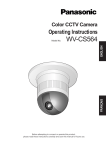
Operating Instructions
Color CCTV Camera
Model No.
WV-CZ392E
WV-CZ492E
This illustration represents WV-CZ392E.
Before attempting to connect or operate this product,
please read these instructions carefully and save this manual for future use.
The model number is abbreviated in some descriptions in this manual.
We declare under our sole responsibility that the
product to which this declaration relates is in
conformity with the standards or other normative
documents following the provisions of Directives
2006/95/EC and 2004/108/EC.
Vi deklarerar härmed vårt fulla ansvar för att den
produkt till vilken denna deklaration hänvisar är i
överensstämmelse med de standarder eller andra
normativa dokument som framställs i direktiv nr
2006/95/EC och 2004/108/EC.
Wij verklaren als enige aansprakelijke, dat het
product waarop deze verklaring betrekking heeft,
voldoet aan de volgende normen of andere
normatieve documenten, overeenkomstig de
bepalingen van Richtlijnen 2006/95/EC en
2004/108/EC.
Ilmoitamme yksinomaisella vastuullamme, että
tuote, jota tämä ilmoitus koskee, noudattaa
s e u r a a v i a s t a n d a rd e j a t a i m u i t a o h j e e l l i s i a
asiakirjoja, jotka noudattavat direktiivien 2006/95/
EC ja 2004/108/EC säädöksiä.
Vi erklærer os eneansvarlige for, at dette produkt,
s o m d e n n e d e k l a r a t i o n o m h a n d l e r, e r i
overensstemmelse med standarder eller andre
normative dokumenter i følge bestemmelserne i
direktivene 2006/95/EC og 2004/108/EC.
Vi erklærer oss alene ansvarlige for at produktet
s o m d e n n e e r k l æ r i n g e n g j e l d e r f o r, e r i
overensstemmelse med følgende normer eller andre
normgivende dokumenter som følger
bestemmelsene i direktivene 2006/95/EC og
2004/108/EC.
CAUTION
RISK OF ELECTRIC
SHOCK DO NOT OPEN
CAUTION: TO REDUCE THE RISK OF ELECTRIC SHOCK,
DO NOT REMOVE COVER (OR BACK).
NO USER-SERVICEABLE PARTS INSIDE. REFER
SERVICING TO QUALIFIED SERVICE PERSONNEL.
The lightning flash with arrowhead
symbol, within an equilateral
triangle, is intended to alert the
user to the presence of uninsulated
dangerous voltage within the
products enclosure that may be of
sufficient magnitude to constitute a
risk of electric shock to persons.
The exclamation point within an
equilateral triangle is intended
to alert the user to the presence
of important operating and
maintenance (servicing)
instructions in the literature
accompanying the appliance.
2
Note:
• The serial number of this product may be
found on the rear of the unit. You should
note the serial number of this unit in the
space provided and retain this book as a
permanent record of your purchase to aid
identification in the event of theft.
Contents
Important safety instructions............................................................................................................. 4
Limitation of liability........................................................................................................................... 5
Disclaimer of warranty....................................................................................................................... 5
Preface.............................................................................................................................................. 6
About notations................................................................................................................................. 6
Features............................................................................................................................................. 6
About the user manuals.................................................................................................................... 6
Precautions........................................................................................................................................ 7
Precautions for installation................................................................................................................ 9
Major operating controls................................................................................................................... 11
Installation and connection............................................................................................................... 12
Basic operation................................................................................................................................. 17
Setup menu....................................................................................................................................... 18
Advanced operation.......................................................................................................................... 21
Quick setup menu....................................................................................................................... 21
Advanced setup menu................................................................................................................ 21
Camera setting............................................................................................................................ 21
Preset position setting................................................................................................................. 29
Special setting............................................................................................................................. 32
Communication setting................................................................................................................ 33
Using the scene select setting menu . ......................................................................................... 34
Language setting........................................................................................................................ 35
Quick setup................................................................................................................................. 35
Password lock setting................................................................................................................. 35
Troubleshooting................................................................................................................................. 37
Specifications.................................................................................................................................... 38
Standard accessories....................................................................................................................... 39
3
Important safety instructions
1) Read these instructions.
2) Keep these instructions.
3) Heed all warnings.
4) Follow all instructions.
5) Do not use this apparatus near water.
6) Clean only with dry cloth.
7)Do not block any ventilation openings. Install in accordance with the manufacturer's
instructions.
8)Do not install near any heat sources such as radiators, heat registers, stoves, or other
apparatus (including amplifiers) that produce heat.
9)Do not defeat the safety purpose of the polarized or grounding-type plug. A polarized
plug has two blades with one wider than the other. A grounding type plug has two
blades and a third grounding prong. The wide blade or the third prong are provided for
your safety. If the provided plug does not fit into your outlet, consult an electrician for
replacement of the obsolete outlet.
10)P rotect the power cord from being walked on or pinched particularly at plugs,
convenience receptacles, and the point where they exit from the apparatus.
11)Only use attachments/accessories specified by the manufacturer.
12)Use only with the cart, stand, tripod, bracket, or table specified by the manufacturer,
or sold with the apparatus. When a cart is used, use caution when moving the cart/
apparatus combination to avoid injury from tip-over.
S3125A
13)Unplug this apparatus during lightning storms or when unused for long periods of time.
14)R efer all servicing to qualified service personnel. Servicing is required when the
apparatus has been damaged in any way, such as power-supply cord or plug is
damaged, liquid has been spilled or objects have fallen into the apparatus, the apparatus
has been exposed to rain or moisture, does not operate normally, or has been dropped.
4
Limitation of liability
THIS PUBLICATION IS PROVIDED "AS IS" WITHOUT WARRANTY OF ANY KIND, EITHER
EXPRESS OR IMPLIED, INCLUDING BUT NOT LIMITED TO, THE IMPLIED WARRANTIES OF
MERCHANTABILITY, FITNESS FOR ANY PARTICULAR PURPOSE, OR NON-INFRINGEMENT
OF THE THIRD PARTY'S RIGHT.
THIS PUBLICATION COULD INCLUDE TECHNICAL INACCURACIES OR TYPOGRAPHICAL
ERRORS. CHANGES ARE ADDED TO THE INFORMATION HEREIN, AT ANY TIME, FOR THE
IMPROVEMENTS OF THIS PUBLICATION AND/OR THE CORRESPONDING PRODUCT (S).
Disclaimer of warranty
IN NO EVENT SHALL Panasonic System Networks Co., Ltd. BE LIABLE TO ANY PARTY OR
ANY PERSON, EXCEPT FOR REPLACEMENT OR REASONABLE MAINTENANCE OF THE
PRODUCT, FOR THE CASES, INCLUDING BUT NOT LIMITED TO BELOW:
(1)ANY DAMAGE AND LOSS, INCLUDING WITHOUT LIMITATION, DIRECT OR INDIRECT,
SPECIAL, CONSEQUENTIAL OR EXEMPLARY, ARISING OUT OF OR RELATING TO
THE PRODUCT;
(2)PERSONAL INJURY OR ANY DAMAGE CAUSED BY INAPPROPRIATE USE OR
NEGLIGENT OPERATION OF THE USER;
(3)UNAUTHORIZED DISASSEMBLE, REPAIR OR MODIFICATION OF THE PRODUCT BY
THE USER;
(4)INCONVENIENCE OR ANY LOSS ARISING WHEN IMAGES ARE NOT DISPLAYED,
DUE TO ANY REASON OR CAUSE INCLUDING ANY FAILURE OR PROBLEM OF THE
PRODUCT;
(5)ANY PROBLEM, CONSEQUENTIAL INCONVENIENCE, OR LOSS OR DAMAGE,
ARISING OUT OF THE SYSTEM COMBINED BY THE DEVICES OF THIRD PARTY;
(6)ANY CLAIM OR ACTION FOR DAMAGES, BROUGHT BY ANY PERSON OR
ORGANIZATION BEING A PHOTOGENIC SUBJECT, DUE TO VIOLATION OF PRIVACY
WITH THE RESULT OF THAT SURVEILLANCE-CAMERA'S PICTURE, INCLUDING SAVED
DATA, FOR SOME REASON, BECOMES PUBLIC OR IS USED FOR ANY PURPOSE.
5
Preface
This product is a 1/4 type CCD color CCTV camera. Connection of this product to a video
monitor allows users to use this product as a monitoring camera.
• WV-CZ392: 36x zoom
• WV-CZ492: 36x zoom, Super Dynamic 6
About notations
The following notations are used when describing the functions limited for specified models.
The functions without the notations are supported by all models.
CZ392
CZ492
The functions with this notation are available when using the model WV-CZ392.
The functions with this notation are available when using the model WV-CZ492.
Features
•
•
•
•
•
•
•
•
•
•
•
•
•
•
•
High quality picture of 976 x 582 pixels
Minimum illumination of 0.5 lx for color mode
Minimum illumination of 0.04 lx for black-and-white mode
Privacy zone feature enables users to veil unwanted zones
Protocol adaptability to Panasonic's protocol
Auto Day/Night mode enables the camera to switch between color and black-and-white
in response to input lights
Built-in digital motion detector and alarm outputs
Super Dynamic 6 can capture clear images of subjects whose illumination is extremely
different CZ492
Up to 256 preset position
Sync is available from internal
Automatic gain control circuit
Image hold
Digital noise reduction effect
Setting change executable only by authorized personnel thanks to the password lock
function
Enhanced horizontal resolution by resolution setting
About the user manuals
The illustrations and screens used in these operating instructions show the case of WV-CZ392.
6
Precautions
The following points as well as the contents of
"Warning" and "Caution" shall be observed.
This product shall be installed in a
vibration-free place.
Refer installation work to the dealer.
Failure to observe this may cause screws
and bolts to be loosened and consequently
to fall resulting in injury.
Installation work requires technique and
experiences. Otherwise injury, or damage to
this product may result.
Be sure to consult the dealer.
Do not insert any foreign objects.
This could permanetly damage this product.
Turn the power off immediately and contact
qualified service personnel for service.
Do not attempt to disassemble or modify
this product.
Failure to observe this may cause fire or
electric shock.
Consult the dealer for the repair or inspections.
Stop operation immediately when
something is wrong with this product.
When smoke goes up from this product or
the smell of smoke comes from this product,
continued use will result in fire, injury, or
damage to the product.
Turn the power off immediately and contact
qualified service personnel for service.
Select an installation area that can
support the total weight.
Selecting an inappropriate installation
surface may cause the product to fall down
or topple over, resulting in injury.
Installation work shall be started after
sufficient reinforcement.
Periodic inspections shall be conducted.
Install this product high enough to ensure
that people don't hit their heads.
Failure to observe this may cause a drop
resulting in injury or accidents.
Do not strike or give a strong shock to
this product.
Failure to observe this may cause injury or fire.
Turn the power off when do wiring of this
product.
Failure to observe this may cause electric
shock. A short circuit or wrong wiring may
cause fire.
Do not use this product in an atmosphere
of flammable gases.
Failure to observe this may cause injury by
explosion.
Avoid installing this product in locations
where it is subject to damage by salt or
corrosive gas.
O t h e r w i s e t h e m o u n t i n g f i x t u re s w i l l
deteriorate, causing the product to fall down
and leading to accidents.
Tighten screws and mounting fixtures to
the specified torque.
Failure to observe this may cause a drop
resulting in injury or accidents.
Rust on the metal parts or screws may cause
the product to fall down resulting in injury or
accidents.
Consult the dealer for the inspections.
7
[Precautions for use]
This product is designed to be used
indoors.
This product is not operable outdoors.
This product has no power switch.
When turning off the power, turn off a circuit
breaker.
Do not aim this product at strong light
sources.
A light source such as a spot light causes a
blooming (light bleeding) or a smear (vertical
lines).
Smear
Bright subject
To keep on using with stable performance
Parts of this product may deteriorate and it
may shorten the lifetime of this product when
using in locations subject to high temperatures
and high humidity. (Recommended operating
temperature: +35 °C {95 °F} or lower)
Do not expose this product to direct heat
sources such as a heater.
Handle this product with care.
Do not drop this product, nor apply shock or
vibration to this product.
Failure to observe this may cause trouble.
Discoloration on the CCD color filter
When continuously shooting a bright light
source such as a spotlight, the color filter
of the CCD may have deteriorated and
it may cause discoloration. Even when
changing the fixed shooting direction after
continuously shooting a spotlight for a
certain period, the discoloration may remain.
8
Blooming
Cleaning this product body
Turn the power off when cleaning this
p ro d u c t . D o n o t u s e s t ro n g a b r a s i v e
detergent when cleaning this product.
Otherwise, it may cause discoloration.
Synchronous mode setting
Image synchronous mode of this camera
indicates internal synchronization (INT) only.
Set the multiplex vertical driver (VD2) as OFF
when the camera is connected to the system
controller of the company.
Precautions for installation
The following points as well as the
contents of "Warning" and "Caution"
shall be observed.
Panasonic assumes no responsibility
for injuries or property damage resulting
from failures arising out of improper
installation or operation inconsistent with
this documentation.
Installation work shall be performed in
accordance with the technology standard
of the electric installation.
This product is designed to be used
indoors.
This product is not operable outdoors.
Do not expose the product to direct sunlight
for hours and do not install the product near
a heater or an air conditioner. Otherwise, it
may cause deformation, discoloration and
malfunction. Keep the product away from
water and moisture.
Installing place
Contact your dealer for assistance if you
are unsure of an appropriate place in your
particular environment.
• Make sure that the installation area is
strong enough to hold the product, such
as a concrete ceiling.
• Install the camera in the foundation area
of the architecture or where sufficient
strength is assured.
• If a ceiling board such as plaster board is
too weak to support the total weight, the
area shall be sufficiently reinforced.
Avoid installing this product in the following locations.
• Location where it may get wet from rain or
water splash.
• Locations where a chemical agent is
used such as a swimming pool.
• Locations subject to steam and oil
smoke such as a kitchen, Locations near
flammable gas or vapor.
• Locations where radiation or x-ray
emissions are produced.
• Locations where corrosive gas is
produced, Locations where it may be
damaged by briny air such as seashores.
• Locations where the temperature is not
within –10 °C to +50 °C.
• Locations subject to vibrations (This
product is not designed for on-vehicle
use.)
Avoid moist or dusty places to install this
system.
Otherwise, lifetime of the internal parts may
be shortened.
Avoid installing this product in a place
with a high level of noise.
Installation near an air conditioner, an air
cleaner, a vending machine, or the like
causes noise.
Be sure to remove this product if it is not
in use.
Keep the camera cable away from the
lighting cable.
Failure to observe this may cause noise.
9
Radio interference
When the camera is used near TV/radio
antenna, strong electric field or magnetic
field (near a motor or a transformer), images
may be distorted and noise sound may be
produced. In such a case, run the camera
cable through specialized steel conduit
tubes.
Locally procure the screws
Screws are not supplied with this product.
Prepare the screws according to the
material, structure, strength and other factors
of the mounting area and the total weight of
objects to be mounted.
Screw tightening
• The screws and bolts must be tightened
with an appropriate tightening torque
according to the material and strength of
the installation area.
• Do not use an impact driver. Failure to
observe this may cause overtightening
and consequently damage to the screws.
• When a screw is tightened, make the
screw at a right angle to the surface. After
tightening the screws or bolts, perform
visual check to ensure tightening is
enough and there is no backlash.
10
Major operating controls
1 Tripod mount base
6 Lens control terminal
2 DC power terminal [12V IN]
3 Power indicator [POWER]
7 Alarm output terminal
4 Operation buttons
1
5 Video output connector
2
2
8 Day/Night input terminal [D/N IN]
9 RS485 data In/Output terminal
2
2
! RS485 terminal select switch
1: Zoom, Focus and Auto Focus can
be controlled by setting button if the
setup menu is not opened.
2: For more information about 6 ~ 9,
refer to page 14.
11
Installation and connection
Important:
• The following installing and connections should be made by qualified service personnel or
system installers in accordance with all local codes.
1 Secure the camera mount bracket (option) to an installation position, and mount the
camera on the camera mount bracket.
Important:
• The camera mount bracket shall be mounted on the foundation part of the construction or
a part with adequate strength.
• When installing on the ceiling, select "ON" for "UPSIDE-DOWN" setting on the setup menu
(refer to page 29).
<Installation sample on a ceiling>
Camera mount
bracket (option)
Screws
(locally procured)
Screws
(locally procured)
• The mounting conditions of the camera mount bracket are described as follows:
Installation
place
Applicable
mount bracket
Recommended
screw
Number of
screw
Minimum pull-out
strength (per 1 pc.)
On ceiling
WV-7011
WV-7010
WV-7012
WV-831
WV-7013
M6
M8
M6
M8
M6
4 pcs.
3 pcs.
3 pcs.
4 pcs.
3 pcs.
196 N
196 N
196 N
921 N
2.25 kN
On wall
For some applicable mount brackets, "A" is attached to the model number. The mounting
conditions are the same even for the A-attached models.
12
2 The video output cable (locally procured) is connected to the video output connector.
Important:
• Be sure to turn off the power of each device before connection.
• Be sure tp secure the coaxial cable connectors.
The maximum extensible length is shown in the table.
Type of coaxial
cable
Recommended
maximum
cable length
m
RG-59/U
(3C-2V)
RG-6/U
(5C-2V)
RG-11/U
(7C-2V)
RG-15/U
(10C-2V)
250
500
600
800
3 Use a cable tie (locally procured) to attach the coaxial cable to the camera mount bracket.
Important:
• The cable tie shall be made of metallic or durable material to be strong enough because
the tie plays the role of camera drop prevention measures in case.
• When the camera mount bracket is mounted on a wall, be sure to observe the mounting
height described on the illustration below.
<Installation sample on a ceiling>
Camera mount
bracket (option)
<Installation sample on a wall>
The cable shall be tied
to the camera mount
bracket to avoid slack.
The cable shall be tied
to the camera mount
bracket to avoid slack.
Camera mount
bracket (option)
More than 270 cm
Floor
13
4 Connet the cable of control terminal to all control terminals.
Control Terminals
1
2
3
4
5
NAME
ZOOM (TELE: +, WIDE: -)
FOCUS (NEAR: +, FAR: -)
IRIS (OPEN: +, CLOSE: -)
COM (For ZOOM, FOCUS, IRIS)
ALARM
6 DAY/NIGHT
7 GND (For ALARM, DAY/NIGHT)
8 RS485 (B)
9 RS485 (A)
I/O
IN
IN
IN
NOTICE
TELE (+3 V - +15 V) WIDE (-3 V - -15 V)
NEAR (+3 V - +15 V) FAR (-3 V - -15 V)
OPEN (+3 V - +15 V) CLOSE (-3 V - -15 V)
OUT Open collector-output max.16 V DC 100 mA
OFF (OPEN)/ON (0 V)
IN Pulled up to 5.0 V DC
OFF (open or 4 V DC-5 V DC)/ON (0 V 0.2 mA)
I/O
I/O
Lens Control Terminal
Control is possible from external equipment by changing ZOOM, FOCUS, and IRIS to "+" or "-".
<Internal Connection Diagram>
ZOOM
3.6
3.6
3.6
FOCUS
IRIS
external
controller etc.
COM
* If you use a lens control terminal, you should not use GND but the COM terminal.
* The COM terminal is used in common with ZOOM, FOCUS, and IRIS.
*To change the polarity of "+" or "-", make a changeover with the "ZOOM INVERSE" or "FOCUS
INVERSE" on the setup menu.
Alarm Output Terminal
Connect an external device such as a buzzer or lamp to the ALM OUT terminal.
DAY/NIGHT Input Terminal
Connect an external sensor to the DAY/NIGHT IN terminal.
Note:
• Use a relay unit if the voltage or current of the connected device exceeds the rating.
• To validate the Day/Night function, set "BW MODE" to "EXT" on the setup menu.
• The GND terminal comes in only one.
If multiple GND lines are required, branches should be made outside the equipment.
14
RS485 Data In/Output Terminal
Control data is transmitted and received to and from other peripherals.
For the farthest camera from RS485 convertor, set the RS485 terminal select switch to RS485
LINE TERM, or Hi-Z for other cameras.
Switch
Right
Switch position
Left
Function
Hi-Z
Terminal resistor
Note:
T(B)
2
T(A)than AWG#22 (0.325 mm )
• Wire gauge size is thicker
difference with the devices in long distance, communications
• Because the existence of potential
R(B)
may be abnormal. Use theR(A)
same GND line or an RS485 isolator (locally procured).
<Half duplex>
Data
Transmission
B
A
Data
Reception
5 Turn on the power.
Important:
• The power supply of 12 V DC shall be insulated against 220 to 240 V AC.
Connect the power supply of 12 V DC:
1 Loosen the screw of the power cord plug (accessory).
2 Connect the power supply of 12 V DC to the power cord plug.
Strip the end of the wire by 3 mm to 7 mm, and twist the stripped part of the wire
sufficiently to avoid short circuit.
Calculation of the relation among the cable length, resistance, and power supply.
The voltage supplied to the camera shall be between 10.8 V DC and 16 V DC.
10.8 V DC ≤ VA - 2 (R x I x L) ≤16 V DC
L: Cable length (m)
R: Resistansce of copper wire (Ω/m)
VA: DC output voltage of power supply unit
I: DC current consumption (A) See specifications
Resistance of copper wire [at 20 ˚C]
Copper wire size
(AWG)
Resistance
#24
#22
#20
#18
#16
(0.205 mm2) (0.325 mm2) (0.519 mm2) (0.833 mm2) (1.307 mm2)
Ω/m
0.083
0.052
0.033
0.020
0.013
15
Cautions:
• Check whether the stripped part of the wire is not exposed and is securely connected.
• To prevent fire or electric shock hazard,use a UL listed cable (WV-1, style 1007) for the DC
power terminal.
• Do not mistake "+" and "-" when connecting the power cable to the DC power terminal of
the camera. It may cause trouble.
• This is not mobile equipment. Never feed the power from a battery source.
3 Tighten the screw of the power cord plug.
4 Connect the power cord plug to the DC power terminal.
(Positive)
(Negative)
Power cord plug
(accessory)
Important:
• Use the provided power cord plug (accessory).
• Make sure that the power cord plug is inserted fully into the DC power terminal, or it may
cause malfunction.
• Use the adapter comply with the power source and consumption (refer to page 38).
16
Basic operation
The description below explains how to operate the setup menu basically.
The operations in the setup menu are performed with the operation buttons after calling up
the setup menu on the connected video monitor.
Screenshot 1
Step 1
Hold down the [SET] button for around 2
seconds to call up the top screen of the
setup menu.
Move the cursor to the item to be set, and
press the [SET] button.
MODEL
WV-CZ392
CAMERA ID
OFF
SCENE SELECT
PRESET POSITION
LANGUAGE
ADVANCED SETUP
Screenshot 2
Step 2
The selected setup screen in the setup
menu appears on the screen.
Perform the settings for each item.
• Selection of setting item:
Press the [UP] or [DOWN] button to move
the cursor.
• Change of settings:
Press the [RIGHT] or [LEFT] button.
• Display of advanced setup screen:
Press the [SET] button when " " is
attached to the target setting item.
• Return to previous setup screen:
Move the cursor to "RET" and press the
[SET] button.
• Return to top screen:
Move the cursor to "TOP" and press the
[SET] button.
PRESET POSITION
PRESET
MAP
HOME POSITION OFF
SELF RETURN
OFF
AUTO MODE
OFF
IMAGE HOLD
OFF
ZOOM INVERSE OFF
FOCUS INVERSE OFF
RET TOP
Step 3
When configure the setting except for quick
setup menu, hold down the [SET] button for
around 2 seconds to quit the setup menu.
17
Setup menu
Performing each setting item in the setup menu should be completed in advance to use this unit.
Perform the settings for each item in accordance with the conditions of the camera shooting area.
List of setup menu
Setup item
CAMERA
CAMERA ID
Description
Performs the camera operation settings.
This item specifies the camera title. The camera title that indicates the
camera location and other information about the camera is created with
alphanumeric characters and symbol, and displayed on the screen.
ALC/MANUAL
SHUTTER
AGC
SENS UP
WHITE BAL
VMD
DNR
BW MODE
Performs settings Light control.
Specifies the electronic shutter speed.
Specifies gain adjustment.
Specifies electronic sensitivity enhancement.
Specifies white balance adjustment.
Performs settings regarding VMD (Video Motion Detector).
Selects the level of the digital noise reduction function.
Performs each setting regarding the black-and-white mode such as
switching between color and black-and-white images.
PRIVACY ZONE
AF MODE
ZOOM LIMIT
Hides undesired portions in the camera shooting area.
Selects auto focus mode.
A limitation is provided to prohibit the ZOOM operation in the direction of
TELE, exceeding the preset value.
Decides whether or not to enable the image stabilizer.
The video image is reversed upside down during ON setting.
STABILIZER
UPSIDE-DOWN
PRESET POSITION
PRESET
MAP
HOME POSITION
SELF RETURN
AUTO MODE
IMAGE HOLD
Selects the position number. The preset setting menu appears on the
monitor screen.
The PRESET POSITION (MAP) menu appears on the monitor screen.
To set a position number for the home position.
Set up the time needed to return to the home position automatically.
Use the auto mode setting to specify the camera movement mode.
The camera picture remains as a still image on the monitor screen until
the camera reaches the preset position.
ZOOM INVERSE The TELE/WIDE operation from the [UP] and [DOWN] buttons is reversed
during ON setting.
FOCUS INVERSE The FAR/NEAR operation from the [LEFT] and [RIGHT] buttons is reversed
during ON setting.
SPECIAL
Performs the special settings.
CHROMA GAIN Adjusts the chroma level.
AP GAIN
Adjusts the aperture level.
PEDESTAL
Adjusts the pedestal (brightness) level.
DISPLAY
Configure the display setting.
PIX OFF
Corrects image defects such as flaws.
REFRESH
The refresh operation is started.
CAMERA RESET Restores the settings in the setup menu to the default settings.
SER.NO.
Displays the serial number of this unit.
COMMUNICATION
Selects RS485 or COAX or COAX (RCV).
SCENE SELECT
Configure the scene select setting.
LANGUAGE
Selects a language to be used in the setup menu.
PASSWORD LOCK
Performs settings password lock.
18
Screen transition diagram
Quick setup (top) screen
"CAMERA ID" screen
WV-CZ392
CAMERA ID. - - -
CAMERA ID
OFF
SCENE SELECT
PRESET POSITION
LANGUAGE
ABCDEFGHIJKLM
NOPQRSTUVWXYZ
MODEL
ADVANCED SETUP
SPACE
- - - - POSI RET RESET
"SCENE SELECT" screen
** SCENE SELECT **
SCENE
INDOOR(L)
LOAD
RET TOP
"PRESET POSITION (MAP)" screen
**PRESET POSITION**
ID:
033-064 225-256
RET TOP
"LANGUAGE SETUP" screen
**LANGUAGE SETUP**
LANGUAGE
ENGLISH
SET
RET TOP
Advanced setup (top) screen
CAMERA
PRESET POSITION
SPECIAL
COMMUNICATION
SCENE SELECT
LANGUAGE
QUICK SETUP
PASSWORD LOCK OFF
19
Screen transition diagram
Advanced setup (top) screen
CAMERA
PRESET POSITION
SPECIAL
COMMUNICATION
SCENE SELECT
LANGUAGE
QUICK SETUP
PASSWORD LOCK OFF
"CAMERA SETUP" screen
**CAMERA SETUP** 1/2
CAMERA ID
OFF
ALC/MANUAL ALC
SHUTTER
AUTO
AGC
ON(MID)
SENS UP
OFF
WHITE BAL
ATW1
DNR
LOW
BW MODE
AF MODE
STOP AF
VMD
OFF
**CAMERA
ZOOM LIMIT
STABILIZER
PRIVACY ZONE
UPSIDE-DOWN
SETUP** 2/2
X36
OFF
OFF
OFF
RET TOP
"PRESET POSITION" screen
**PRESET POSITION**
PRESET
MAP
HOME POSITION OFF
SELF RETURN
OFF
AUTO MODE
OFF
IMAGE HOLD
OFF
ZOOM INVERSE OFF
FOCUS INVERSE OFF
RET TOP
"SPECIAL SETUP" screen
**SPECIAL SETUP**
CHROMA GAIN
····I··160
AP GAIN
··I···· 22
PEDESTAL
·I····· 16
+
DISPLAY
ALARM
PIX OFF
REFRESH
PUSH SET
CAMERA RESET PUSH SET
SER.NO. BFB03964
RET TOP
"COMMUNICATION SETUP" screen
**COMMUNICATION SETUP**
COMMUNICATION COAX
RET TOP
"SCENE SELECT" screen
**SCENE SELECT**
INDOOR(L)
SCENE
LOAD
RET TOP
"LANGUAGE SETUP" screen
**LANGUAGE SETUP**
LANGUAGE
ENGLISH
SET
RET TOP
Quick setup (top) screen
MODEL
WV-CZ392
CAMERA ID
OFF
SCENE SELECT
PRESET POSITION
LANGUAGE
ADVANCED SETUP
"PASSWORD SETUP" screen
** PASSWORD? **
0 1 2 3 4 5 6 7 8 9
OK RESET
NEW PASSWORD
RET TOP
20
Advanced operation
Quick setup menu
Hold down the [SET] button for around 2
seconds to call up the camera setup menu.
Following items can be set on the quick
setup menu.
• Camera Identification Setting (refer to this page)
• Scene select setting (refer to page 34)
• Preset position setting (refer to page 29)
• Language setting (refer to page 35)
• Advanced setting (refer to this page)
MODEL
WV-CZ392
CAMERA ID
OFF
SCENE SELECT
PRESET POSITION
LANGUAGE
ADVANCED SETUP
The setting steps of Quick setup menu is
the same as Advanced setup menu.
Change from Quick setup menu to
Advanced setup menu, move the cursor
to "→ ADVANCED SETUP" and press the
[SET] button.
Advanced setup menu
Display the Advanced setup menu through
the Quick setup menu.
1. Display the Quick setup menu (refer to this
page), move the cursor to "→ ADVANCED
SETUP" and press the [SET] button.
CAMERA
PRESET POSITION
SPECIAL
COMMUNICATION
SCENE SELECT
LANGUAGE
QUICK SETUP
PASSWORD LOCK OFF
All the setting can be configured by pressing the
[SET] button. When "ON" is selected for Password
lock, all the setting cannot be configured. Reset
the password lock then configure the setting.
The information about how to reset the
password lock, please refer to page 35.
Camera setting
• To Display the Camera Setup
Menu
Move the cursor to "CAMERA ", and
press the [SET] button. The "CAMERA
SETUP" menu appears. (refer to this page)
1 Camera Identification Setting
**CAMERA SETUP** 1/2
CAMERA ID
OFF
ALC/MANUAL ALC
SHUTTER
AUTO
AGC
ON(MID)
SENS UP
OFF
WHITE BAL
ATW1
DNR
LOW
BW MODE
AF MODE
STOP AF
VMD
OFF
**CAMERA
ZOOM LIMIT
STABILIZER
PRIVACY ZONE
UPSIDE-DOWN
SETUP** 2/2
X36
OFF
OFF
OFF
RET TOP
The camera ID consists of up to 16
alphanumeric characters.
The camera ID display can be switched on
or off on the monitor screen.
To edit the CAMERA ID
1. Move the cursor to "CAMERA ID".
2. The cursor on the letter "0" is highlighted.
3. Move the cursor to the character you
want to edit.
4. After selecting the character, press the
[SET] button. The selected character
appears in the editing area.
5. Repeat the steps above until all
characters are edited.
CAMERA ID. - - ABCDEFGHIJKLM
NOPQRSTUVWXYZ
SPACE
- - - - POSI RET RESET
21
To enter a blank space in the camera ID
(1) ALC Mode with BLC "ON"
Move the cursor to "SPACE" and press the
[SET] button.
To erase all characters in the editing area
1. Press the [SET] button after selecting
"ALC". The "ALC CONT" menu appears.
**ACL CONT**
BACK LIGHT COMP
Move the cursor to "RESET" and press the
[SET] button. All characters in the editing
area disappear.
To determine the display position of the
camera ID
1. Move the cursor to "POSI", and press
the [SET] button. The display in the
figure appears and the camera ID is
highlighted.
2. Move the camera ID to the desired
position.
3. Press the [SET] button to fix the position
of the camera ID.
WV-CZ392
CZ392
BLC
ON
LEVEL
·I····· 0
RET TOP
2. Move the cursor to the BLC parameter
and select "ON".
3. If you want to adjust the video output
level, adjust the "I" cursor for "LEVEL".
(2) ALC Mode with BLC "OFF" CZ392
1. Move the cursor to "BLC" and select
"OFF". (When you select "MANUAL", BLC
is not available.)
**ACL CONT**
BACK LIGHT COMP
BLC
MASK SET
LEVEL
2 Light Control Setting
1. Move the cursor to "ALC/MANUAL" and
select "ALC" or "MANUAL". When you
select "ALC", backlight compensation
"ON" or "OFF" can be set.
Default setting: ALC
OFF
·I····· 0
RET TOP
2. Move the cursor to "MASK SET " and
press the [SET] button, the mask setting
menu appears.
Blinking
2. When "MANUAL" is selected, press the
[SET] button and the "MANUAL CONT"
menu appears. Press the [LEFT] or
[RIGHT] button for iris adjustment.
**MANUAL CONT**
IRIS
RET TOP
22
···I···+64
CLOSE OPEN
3. To mask an area where backlight is
bright, move the cursor to the area and
press the [SET] button. The mask turns
white.
Once the flicker display moves to the
mask area, white and stripe will display
alternatively in this area.
Repeat this procedure to mask the
desired areas.
Loss of detail in
dark areas
Change to
white
Blinking
4. To cancel a masked area, move the
cursor to the area, and press the [SET]
button. To delete all the masking area,
press the [RIGHT] and [LEFT] buttons at
the same time for more than 2 seconds.
5. After masking is completed, press the [SET]
button more than 2 seconds. 48 mask
areas on the monitor screen disappear and
the "ALC CONT" menu appears.
(3) SUPER-D6 (Super Dynamic 6) CZ492
Note:
1. When "ALC" is selected, press the [SET]
button, SUPER-D6 can be set.
2. Move the cursor to "SUPER-D6", select
"ON" or "OFF" and press the [SET] button.
ON: Turns on SUPER-D6.
OFF: Turns off SUPER-D6.
Default setting: OFF
3 Shutter Speed Setting
**ALC CONT**
BACK LIGHT COMP
SUPER-D6
OFF
LEVEL
·I····· 0
MASK SET
Two images
digitally combined
to create a clear
final image.
• When "OFF" is selected for "SUPER-D6", please
refer to the setting of Mask area in page 22.
• When "ON" is selected for "SUPER-D6",
increase the level can obtain better effect.
But if the level is too high, afterimage and
noise maybe increased.
Shutter speed changes as follows:
OFF
SUPER-D6 (Super Dynamic 6)
When there is wide variation between the
illumination of light and dark areas of the
location being monitored, the camera adjusts
the lens iris in accordance with the bright
areas. This causes loss of detail in dark
areas. Conversely, adjusting lens brightness
for the dark areas cause brighter area to
become washed out. SUPER-D6 digitally
combines an image that is set up for a clear
view of bright areas with an image that is set
up for a clear view of dark areas, creating a
final image that preserves overall detail.
AUTO
AUTO
When "ON" is selected for "SUPER-D6", Shutter
speed changes as follows: CZ492
OFF
CZ392
When "OFF" is selected for "SUPER-D6", Shutter
speed is changing as follows: CZ492
OFF
RET TOP
Wa s h o u t o f
bright areas
AUTO
AUTO:When shooting the bright object
in outdoor, Shutter will be started
to obtain more clear picture.
OFF: fix to 1/50s
Default setting: AUTO
23
• When the selected shutter speed caused
flicker on condition that fluorescent lamps
stay on, change this setting to "OFF".
• When "MANUAL" is selected for "ALC/
MANUAL" and "FIX" is selected for "SENS UP",
"AUTO" can be selected for "SHUTTER", but
the AUTO function is not available.
4 Gain Control Setting
Select "ON (LOW)", "ON (MID)", "ON (HIGH)" or "OFF".
Default setting: ON (MID)
Note:
• Even if "AGC" is set to "ON" and if the noise
reduction functionis enabled, after images may
be produced by shooting a moving object.
• For more information, refer to Digital
Noise Reduction on page 25.
5 SENS UP Setting
The electronic sensitivity enhancement
mode changes as follows: CZ392
AUTO
OFF
AUTO
AUTO
AUTO
FIX
AUTO
FIX
FIX
256 FIX
AUTO
AUTO
AUTO
FIX
FIX
512 FIX
FIX
128 FIX
AUTO
OFF
FIX
256 FIX
AUTO
FIX
FIX
FIX
512 FIX
When "ON" is selected for "SUPER-D6",
the electronic sensitivity enhancement
mode changes as follows: CZ492
OFF
FIX
128 FIX
AUTO
FIX
When "OFF" is selected for "SUPER-D6",
the electronic sensitivity enhancement
mode changes as follows: CZ492
OFF
AUTO
OFF
FIX
FIX
AUTO
Default setting: OFF
Note:
24
FIX:If selected "X32 FIX", SENS UP will
increase up to X32 fixedly.
• Noise or spots may appear in the picture
when the sensitivity of the camera is
increased.
Note:
• The difference between "AUTO" and "FIX"
are as follows:
AUTO:If selected "X32 AUTO", SENS UP
will increase up to X32 automatically.
6 White Balance Setting
1. ATW1/ATW2:in this mode, the camera
continually monitors the
color temperature of the light
source and automatically
adjusts white balance.
ATW1: 2700 K to 6000 K.
ATW2:2000 K to 6000 K (Mode
recommended for sodium lighting)
Default setting: ATW1
Proper white balance may not be possible
under the following conditions. In such
cases, use the "AWC" while balance mode.
• When the subject contains mostly dark
colors
• When the light source is a deep blue sky
or twilight
• When illumination of the subject is low
(1)The white balance of the camera is
automatically adjusted at ATW1 and ATW2.
**AWT1**
R
···I··· 0
B
···I··· 0
RET TOP
(2)For fine adjustment of ATW1/ATW2, press the
[SET] button. The ATW1/ATW2 fine adjustment
menu appears on the monitor screen.
2. AWC: Automatic White Balance Control
In this mode, the supported color
temperature range is approximately 2000 K
to 10000 K. This mode is best in locations
where the light source is constant.
(1)Select "AWC" and press the [SET] button.
(2)"PUSH SET" is highlighted on the display
while white balance adjustment is being
performed.
• "PUSH SET" becomes unhighlighted again
when white balance adjustment is complete.
• If white balance adjustment cannot be
completed for some reason, "PUSH SET"
will remain highlighted on the display. If
this happens, it could mean that the color
temperature is outside the supported
range, or that illumination is too low.
(3)For fine adjustment of the "AWC" press
the [RIGHT] button, select "AWC ".
The AWC fine adjustment menu appears
on the monitor screen.
Note:
• When "AUTO" is selected, it is recommended
to set "AGC" to "ON" before use.
• At the time of "EXT" setup, the controller
cannot be used for ON/OFF control.
2. When "AUTO" is selected, it becomes possible
to set up the LEVEL and DURATION TIME.
**BW MODE**
**AWC**
R
···I···
0
B
···I···
0
BW
AUTO
LEVEL
HIGH
DURATION TIME ·I··
S L
BURST(BW)
ON
RET TOP
RET TOP
7 Digital Noise Reduction
DNR may be used to improve quality
under low light conditions.
There are 2 levels of DNR, which may be
selected depending on local site conditions.
LOW: Low DNR, Low afterimage.
HIGH: High DNR, High afterimage.
Default setting: LOW
8 Black-and-white Mode Setting
You can set up the BW mode on this menu.
BW Setting
1. Move the cursor to "BW" and select "EXT",
"AUTO", "ON" or "OFF".
**BW MODE**
BW
OFF
BURST(BW)
ON
RET TOP
EXT:Changes between the color and
black-and-white mode according to
the D/N IN terminal.
AUTO:The camera selects the black-and-white
mode if the picture is dark, or the color
mode if the picture is bright enough.
ON: T
he black-and-white mode is selected.
OFF: The color mode is selected.
Default setting: OFF
3. When "AUTO" is selected, move the cursor
to "LEVEL" and press the [LEFT] and
[RIGHT] buttons to set the illuminance when
switching to black-and-white or color mode.
The illuminance shown below is based on
the assumption that the camera is used in
an area lit by halogen lamps.
LOW:Switches to the black-and-white
mode when illuminance around the
camera is approximately 1.5 lx or
lower (when AGC ON (MID), SENS
UP OFF is set).
HIGH:Switches to the black-and-white
mode when illuminance around
the camera is approximately 3 lx or
lower (when AGC ON (MID), SENS
UP OFF is set).
Default setting: HIGH
Note:
• When near-infrared lamps are used, the
image may be displayed out of focus
and mode switching may not perform
automatically.
4. Move the cursor to "DURATION TIME".
The camera determines whether to switch the
mode when the time set for holding a picture
motionless on the screen has elapsed.
Available duration times:
(S) 2 s 10 s 30 s 60 s (L)
Default setting: 10 s
25
BURST (BW) Setting
Move the cursor to select "ON" or "OFF".
ON:The burst signal is supplied along with
the black-and-white composite video.
OFF: The burst signal is not output.
Default setting: ON
Note:
• With some monitors and VTR models, output of a
camera images in the black-and-white mode will
not display a proper image unless a burst signal
is provided. Select "ON" for this setting when
using equipment that requires a burst signal.
9 Auto Focus Setting
STOP AF:The AF mode activates during
or after lens operation.
AUTO:The AF mode activates when the
illuminance is changed.
Default setting: STOP AF
Note:
• Long use in "AUTO" mode may shorten
the service life of the lens drive.
• Auto-focus may not be possible with the
types of objects listed below. For such
objects, focus manually.
1.Dirt or water on window glass.
2.Low lighting or illumination.
3.Bright objects or high intensity objects.
4.Single color object such as a white wall
or fine felt.
5.sloping objects.
Auto-focus focuses on the object in the center
of the picture, so objects around the outside
periphery of the picture will not be in focus.
! Motion Detector Setting
1. Select "OFF", "MOTION DET" or "SCENE CHANGE".
OFF: Turns off the motion detector.
MOTION DET:Alarm signal is output when
motion is detected in the
image. Selecting "MOTION
DET" and pressing the
[SET] button displays the
"MOTION DET" menu, which
can be used for configuring
detailed settings.
26
SCENE CHANGE:Alarm signal is output
when the camera is
covered by cloth, a lid,
spray paint or something.
Default setting: OFF
VMD
The motion detector divides the screen
into 48 blocks and monitors changes in the
luminance in each block. When it detects
any change (movement) in the image, it
outputs an alarm signal. When a change
(movement) in the image is detected
while in the auto mode, the alarm signal is
output and the camera stops at the preset
position for a specified amount of time.
Important:
Conditions for SCENE CHANGE
Monitoring might not be possible in the
following situations.
• If only one part of the screen is not
covered, or if the covering is translucent.
Also, false detection might occur in the
following situations.
• When extreme changes in lighting
occur, such as turning lights on an off.
• If pedestrian or vehicle traffic is heavy.
Note:
• If you want to set a motion detector for
each preset position, do the scene file
setting. (refer to page 31)
2. Select "MOTION DET" and press the [SET]
button, "MOTION DET" menu appears.
Mask setting can be set in this menu.
**MOTION DET**
LEVEL
DWELL TIME
DISPLAY MODE
ALARM
MASK SET
RECOVER TIME
···I···131
2S
OFF
OFF
RET TOP
3. Move the cursor to "MASK SET " and
press the [SET] button, 48 mask areas
appears on the monitor screen.
For more information, refer to Light
Control Setting on page 22.
4. After masking areas, press the [SET]
button more than 2 seconds. "MOTION
DET" menu appears on the monitor screen.
5. Move the cursor to "ALARM", select "ON"
or "OFF".
ON: Turns on alarm output in the demo mode.
OFF: Turns off alarm output in the demo mode.
Default setting: OFF
6. Move the cursor to "DISPLAY MODE ", press
the [SET] button to see the present setting.
Demo Mode
The demo mode divides the screen into
48 blocks and monitors changes in the
luminance in each block. It also masks
any part of the picture where there is
a change in average luminance that
exceeds the currently specified detection
sensitivity level. The demo mode results
can be used to determine the optimum
detection sensitivity level (step 7) and
the areas of the screen that need to be
masked (step 3).
7. Move the cursor to "LEVEL", press the
[LEFT] and [RIGHT] buttons to set the
level. Move to "+", the level increases,
move to "-", the level decreases. Repeat
steps 6 and 7 to obtain the optimum
detection level.
Detection Conditions
Object Size:The picture size on the screen
should be larger than 1/48 of
the actual picture size.
Subject Contrast:The contrast ratio between
the background and the
moving object must be at
least 5 % (at the maximum
LEVEL setting).
Object Speed:The allowable time range
for the object to pass from
one edge of the screen
to the other is 0.1 second
to 0.8 second. Movement
that is faster or slower than
this cannot be detected.
But when the contrast ratio between the
background and the moving object is
sufficient, the restriction to object size
and speed can be relaxed.
8. Move the cursor to "DWELL TIME", press
the [LEFT] and [RIGHT] buttons to select
an alarm detect dwell time.
After alarm detection, the next alarm is not
detected until the specified dwell time elapses.
Display in the sequence shows as below.
2S
5S
10S
30S
Default setting: 2S
9. Move the cursor to "RECOVER TIME", and
press the [LEFT] or [RIGHT] button to
select an alarm reset time setting.
Display in the sequence shows as follows.
When "OFF" is selected, it cannot be reset
before other operation.
1 MIN
2 MIN
3 MIN
5 MIN
OFF
60 MIN
30 MIN
20 MIN
10 MIN
Default setting: OFF
Note:
• Use the mask setting to mask areas where
there is wind movement of curtains, etc.
• Use a lower sensitivity level (LEVEL)
setting for areas where illumination is
low and prone to digital noise. Also note
that operation error can occur when
the illuminance of a subject is changed
suddenly by the headlights of passing
cars, turning lights on or off, etc.
• There is a delay of about 0.2 second from
the point that the camera detects change
(movement) in the image and the point
that a signal is sent to the alarm terminal
of a VTR, etc.
• Alarms are not output when ZOOM,
FOCUS or other functions are operating.
• When the motion detector is set to "MOTION
DET" or "SCENE CHANGE", it outputs alarm
data during the blanking period. This can
cause operational problems for a VTR or
other device that uses a time code signal,
etc. Turn off the motion detector when not
using coaxial communication.
• The motion detector is not intended for
use as specialty device for the prevention
of theft, fire, etc. The manufacturer
assumes no responsibility for any
accidents that occur or any losses
incurred while this product is being used.
27
" Zoom Limit Setting
A limitation is provided to prohibit the
ZOOM operation in the direction of TELE,
exceeding the preset value.
Digital zoom: X36 - X720
Optical zoom: below X36
# Stabilizer
This function electronically compensates
for an unstable camera image due to
movement of a mounting pole or bracket.
1. Move the cursor to "STABILIZER" and select
"ON" or "OFF".
ON:Automatically compensates for an
unstable image.
OFF: Image stabilizer will not operate.
Default setting: OFF
$ Privacy Zone Setting
Up to 8 unwanted zones can be masked
on the monitor screen.
1. Move the cursor to "PRIVACY ZONE",
press the [LEFT] and [RIGHT] buttons
and select among "ON (1)", "ON (2)" or
"OFF". Then press the [SET] button.
ON (1): Turns on the privacy zone function.
(Grey)
ON (2): Turns on the privacy zone function. (Mosaic)
OFF: Turns off the privacy zone function.
Default setting: OFF
2. When "ON (1)" or "ON (2)" is selected for
"PRIVACY ZONE" then press the [SET] button.
This will display the "ZONE NUMBER"
selection menu. The picture will be X1
wide angle (WIDE) if there is no privacy
zone defined for the current zone number.
**ZONE NUMBER 1/8**
RET TOP
3. Move the cursor to "ZONE NUMBER", and then
press the [LEFT] or [RIGHT] button to select
the zone number (1 to 8) you want to configure.
An asterisk (*) to the right of the number
indicates that it already has a privacy
28
zone configured for it. Selecting such a
zone number zooms the picture to the
zoom setting that was in effect when its
privacy zone settings were configured.
4. Press the [SET] button.
The appearance of the menu depends on
zone settings.
**ZONE NUMBER 1/8**
ZOOM/FOCUS
PUSH SET
POSITION
PUSH SET
ZONE SCALE
PUSH SET
ZONE LEVEL
SET DEL
RET TOP
··I····2
+
5. Move the cursor to "→ PUSH SET" to the
right of "ZOOM/FOCUS", and then press
the [SET] button.
This will display the ZOOM/FOCUS
setting menu.
**ZONE NUMBER 1/8**
ZOOM/FOCUS
PUSH SET
POSITION
PUSH SET
ZONE SCALE
PUSH SET
ZOOM
ZONE LEVEL
SET DEL
RET TOP
FOCUS
··I····2
+
6. Press the [UP], [DOWN], [RIGHT] or [LEFT]
button to adjust the zoom and focus
positions, and then press the [SET] button.
This completes the adjustment procedure
and returns to the zone setting menu.
Privacy zone should be set under low
magnification. If the privacy zone is set
under high magnification, it may shift.
7. Move the cursor to "→ PUSH SET" to the right
of "POSITION", and press the [SET] button.
This will display the POSITION setting menu.
8. Press the [UP], [DOWN], [RIGHT] or [LEFT]
button to set up the mask position of the
privacy zone, and then press the [SET] button.
This completes the setting procedure and
returns to the zone setting menu.
9. Move the cursor to "→ PUSH SET" to the right
of "ZONE SCALE", and press the [SET] button.
This will display the ZONE SCALE setting
menu.
10.Press the [UP], [DOWN], [RIGHT] or
[LEFT] button to set up the mask size
of the privacy zone, and then press the
[SET] button.
This completes the setting procedure
and returns to the zone setting menu.
11.When "ON (2)" is selected for "PRIVACY
ZONE", move the cursor to "ZONE
LEVEL", and press the [LEFT] and [RIGHT]
buttons to set the level of privacy zone.
12.Move the cursor to "SET", and then press
the [SET] button.
This completes the privacy zone setting
procedure and returns to the zone
number selection menu.
Selecting "DEL" deletes the zone settings.
Note:
• After setting the privacy zone, dislocation
will occur in the mask zone when upsidedown inverse is used.
Preset position setting
**PRESET POSITION**
PRESET
MAP
HOME POSITION OFF
SELF RETURN
OFF
AUTO MODE
OFF
IMAGE HOLD
OFF
ZOOM INVERSE OFF
FOCUS INVERSE OFF
RET TOP
1 Preset Menu Display
1. Displaying the preset menu directly
(1)Move the cursor to "PRESET" and
select the position number.
(2)Press the [SET] button. The preset setting
menu appears on the monitor screen.
2.Displaying the preset menu from the
"PRESET POSITION" (MAP) menu.
(1)Move the cursor to "MAP " and
press the [SET] button. The "PRESET
POSITION" (MAP) menu appears on the
monitor screen.
**PRESET POSITION**
% Upside-Down Setting
OFF:The video image cannot be reversed
upside down.
ON:The video image can be reversed
upside down.
Default setting: OFF
ID:
033-064 225-256
RET TOP
**PRESET POSITION**
ID:
065-096 001-032
RET TOP
(2)Move the cursor to the position
number to be set and press the [SET]
button. The preset setting menu
appears on the monitor screen.
To display any position number
between 33 and 64, move the cursor
to "033-064" in the lower left of the
screen and press the [SET] button.
29
B Preset Identification Setting
Note:
• The "*" mark indicates that the position
number has been preset.
• The character "H" refers to the home position.
• The second line from the bottom shows
the preset ID corresponding to the
selected number. Preset Position can be
displayed in the right of "ID".
PRESET NO.
1
POSITION SET
PRESET ID
ON
ALC/MANUAL
ALC
AF MODE
NORMAL
DWELL TIME
10S
SCENE FILE
OFF
1.Move the cursor to "PRESET ID" on the preset
setting menu and select "ON" or "OFF".
ON: Preset ID appears on the monitor screen.
OFF: Preset ID does not appear.
Default setting: ON
2.Press the [SET] button to display the
PRESET ID menu.
Move the cursor to "COPY" and press
the [SET] button. The preset ID in
the preceding positionis immediately
shown. Each consecutive pressing
of the [SET] button displays the ID
preceding the one currently displayed.
A Position Setting
1.Move the cursor to "POSITION SET " on
the preset setting menu and press the
[SET] button.
The POSITION setting menu appears.
(1)Move the cursor to "→ PUSH SET" for
"ZOOM/FOCUS" and press the [SET]
button.
**POSITION
ZOOM
PRESET NO.
1*
0123456789
ABCDEFGHIJKLM
NOPQRSTUVWXYZ
SPACE
COPY POSI RET RESET
1 **
PUSH SET
FOCUS
30
(2)Select a zoom position and a focus
position, and then press the [SET]
button. The positions are set and the
screen returns to the position setting
menu.
To Edit a Preset ID
Move the "↑" to the characters to be
changed by pressing the [LEFT]
and [RIGHT] buttons, and enter new
characters follow the steps in "To edit
the CAMERA ID" (refer to page 21).
RET TOP
For registration, refer to the items of
CAMERA ID on page 21.
To Copy a Preset ID from Another Position
RET TOP DEL
ZOOM/FOCUS
To Enter a New Preset ID
To Delete a Preset ID
Please refer to "To erase all characters
in the editing area" in page 22.
To Enter the Next ID without
Returning to the Preset Setting Menu
Note:
• If you move the cursor to the position
number and press the [LEFT] or [RIGHT]
button, the position number can be
selected. The selected preset position
number can also be set after pressing the
[SET] button.
(1)In the preset ID setting menu, move
the cursor to the top line and select
a desired position number and
press the [SET] button.
(2)Enter, copy, change or delete the ID
as described above.
C Light Control Setting
Select "ALC" or "MANUAL".
Default setting: ALC
D Auto Focus Setting
Move the cursor to "AF MODE" and
press the [LEFT] and [RIGHT] buttons to
configure the auto focus setting.
NORMAL:Press the [AF] button on the
camera, auto focus activates.
STOP AF:The AF mode activates during
or after lens operation.
AUTO:The AF mode activates when the
illuminance is changed.
Default setting: NORMAL
E Dwell Time setting
Move the cursor to "DWELL TIME" and
select a dwell time setting.
The stop time display in the sequence
shows as follows.
**SCENE FILE
2S
4MIN
3S
5S
3MIN
10S
2MIN
30S
1MIN
Default setting: 10S
PRESET NO.
1
POSITION SET
PRESET ID
ON
ALC/MANUAL
ALC
AF MODE
NORMAL
DWELL TIME
10S
SCENE FILE
OFF
SHUTTER
AGC
SENS UP
WHITE BAL
VMD
RET TOP
G Deleting Preset Positions
Move the cursor to "DEL" and press the
[SET] button.
2 Home Position Setting
1.To set a position number for the home position
Move the cursor to "HOME POSITION"
and select a desired position number.
2.Select "OFF" if you are not using the
home position function.
3 Self Return Setting
RET TOP DEL
1. Selecting a Scene File
Move the cursor to "SCENE FILE", select
the number of the scene file (1-10 or OFF).
When select "OFF", scene file cannot
be selected.
Default setting: OFF
2. Configuring Scene File Settings
Move the cursor to "SCENE FILE" and
press the [SET] button. "SCENE FILE"
menu appears.
The following items can be set in
Scene File menu.
More information please refer to the
camera setting.
•Shutter (refer to page 23)
•AGC (refer to page 24)
•SENS UP (refer to page 24)
•White balance (refer to page 24)
•VMD (refer to page 26)
This menu is used to set up the time needed
to return to the home position automatically.
1.Move the cursor to "SELF RETURN",
select a self return time. Then press the
[SET] button.
Self return display in the sequence
shown below.
OFF 1S 2S 3S 4S
5S
7S
8S
9S 10S 20S
F Scene File Setting
1**
AUTO
ON(MID)
OFF
ATW1
OFF
40S
4MIN
30MIN
50S
1MIN
2MIN
5MIN
10MIN
60MIN
6S
30S
3MIN
20MIN
Default setting: OFF
2.If you selected any setting other than
"OFF" in step 1, press the [SET] button.
Press the [LEFT] and [RIGHT] buttons
to return to self return mode.
OFF:In the auto mode, exits the auto
mode.
AUTO:Returns to the auto mode when
the trigger time elapses. When
"AUTO MODE" is setting "OFF",
returns to the home position
when the trigger time elapses.
HOME:Returns to the home position
when the trigger time elapses.
31
SEQ:Activates the sequence function
when the trigger time elapses.
SORT:Activates the sort function when
the trigger time elapses.
Default setting: AUTO
4 Auto Mode Setting
Use the auto mode setting to specify the
camera movement mode (OFF, SEQ, SORT).
Move the cursor to "AUTO MODE", select
a camera movement mode.
OFF: Manual movement only
SEQ:Sequentially switches between
preset positions in position number
sequence. (sequential movement)
SORT:Sequentially switches between
preset positions counterclockwise,
starting rom the camera home
position. (sort movement)
Default setting: OFF
5 Image Hold
The camera picture remains as a still
image on the monitor screen until the
camera reaches the preset position. This
function is useful for surveillance via local
area network.
Move the cursor to "IMAGE HOLD" and
select "ON" or "OFF".
Default setting: OFF
6 ZOOM INVERSE
The TELE/WIDE operation from the [UP]
and [DOWN] buttons is reversed during
"ON" setting.
7 FOCUS INVERSE
1 Chroma Level
2 Aperture Level
3 Pedestal Level
Move the cursor to "CHROMA GAIN", "AP
GAIN" and "PEDESTAL" and move the "I"
cursor to your desired position.
4 Setting the display
Move the cursor to "DISPLAY" and select
a display setting.
ALARM:Only alarm is displayed. Zoom
position is not displayed.
OFF:Zoom position displays and alarm
are not displayed.
ALL:Zoom position displays and alarm
are all displayed.
POSITION:Only zoom is displayed.
Alarm is not displayed.
Default setting: ALARM
5 PIX OFF Setting
In this setting, you can assign a blemish
position and compensate the blemish.
1.Move the cursor to "PIX OFF " and
press the [SET] button. The "PIX OFF"
menu appears.
** PIX OFF **
1
5
9
13
2
6
10
14
3
7
11
15
4
8
12
16
The FAR/NEAR operation from the [LEFT]
and [RIGHT] buttons is reversed during
"ON" setting.
Special setting
**SPECIAL SETUP**
CHROMA GAIN
····I··160
AP GAIN
··I···· 22
PEDESTAL
·I····· 16
+
DISPLAY
ALARM
PIX OFF
REFRESH
PUSH SET
CAMERA RESET PUSH SET
SER.NO. BFB03964
RET TOP
32
000 000
RET TOP
2.Select a number and press the [SET]
button. The blemish compensation
position setting screen appears.
Move the "+" cursor to the place on the
blemish position. After moving the "+"
cursor to a position where the blemish
looks inconspicuous, press the [SET]
button. Consequently, the blemish
compensation position is set up and
the "PIX OFF" menu is restored. After a
blemish compensation position is set up,
"*" is attached at the right of the number.
3.If you would like to delete a blemish
compensation position, move the cursor to the
applicable number and press the [SET] button.
The blemish compensation position
setting screen appears. The blemish
compensation position is deleted and
"*" is also deleted from the right of the
number by pressing the [RIGHT] and
[LEFT] buttons for more than 2 seconds.
6 REFRESH
Move the cursor to "→ PUSH SET" to the
right of "REFRESH" and press the [RIGHT]
and [LEFT] buttons at the same time for
more than 2 seconds. Then, the Refresh
operation is started.
The refresh function corrects the camera
position when it starts to deviate from the
preset positions.
7 CAMERA RESETTING
Move the cursor to "→ PUSH SET" to the
right of "CAMERA RESET" and press the
[RIGHT], [LEFT], and [SET] buttons at the
same time for more than 2 seconds.
The camera is reset to the factory default settings.
8 SER.NO.
Display the serial number of this unit.
Note:
• Any of the following cannot be reset to the
factory defaults: Preset Position Setting
(POSITION SET, ALC/MANUAL, AF MODE,
SCENE FILE), Communication Setting,
Password Lock Setting, PIX OFF setting.
• In case of performing this operation on
the condition that the cursor is positioned
on other than CAMERA RESET, you
cannot perform the operations on the
menu thereafter. In that event, set the
camera menu to ON again.
Communication setting
**COMMUNICATION SETUP**
COMMUNICATION COAX
RET TOP
Move to the cursor to "COMMUNICTION" and
select "RS485 " or "COAX" or "COAX (RCV)".
COAX:Communication is carried out in
the coaxial multiplex system.
COAX (RCV):If our receiver (WV-RC100,
WV-RC150, WV-RC170) is
used, select "COAX (RCV)".
RS485:Communication is maintained
through the RS485 terminal.
Selecting "RS485 " and the [SET]
button is pressed, the "RS485
SETUP" menu is displayed.
Default setting: COAX
• Changing the Camera
Communication Parameters for
RS485.
**RS485 SETUP**
1
UNIT NUMBER
----SUB ADDRESS
19200
BAUD RATE
8
DATA BIT
PARITY CHECK NONE
1
STOP BIT
NOT USE
XON/XOFF
OFF
WAIT TIME
AUTO2
ALARM DATA
OFF
DELAY TIME
RET TOP
Move the cursor to the item and select
the parameter.
Unit Number
In an RS485 chain each unit must have a
unique number.
Sub Address
Do not set. When use Pelco
communication, press the [RIGHT] button,
the sub address will display "----P", unit
number will display "P1 D96", at this time
Pelco-P address will be "1", Pelco-D
address will be "96". Unit address can be
changed by changing unit number.
33
Baud Rate
Specifies the transmission speed ("2400",
"4800", "9600", "19200" bit per second) for
the RS485 communication.
Default setting: 19200
Specifies the number of data bits ("7" or
"8" bits) for the RS485 communication.
Default setting: 8
Note:
Specifies the parity check mode ("NONE",
"ODD", "EVEN").
Default setting: NONE
Specifies the number of stop bits ("1" or "2" bits).
Default setting: 1
Stop Bit
X ON/X OFF
Specifies whether to apply flow control or
not ("USE" or "NOT USE").
Default setting: NOT USE
Wait Time
Specifies the time to wait until retrying
after confirming that no data is received
from the controller.
(OFF: no retry, 100, 200, 400, 1000 ms).
OFF
100MS
200MS
400MS
1000MS
Default setting: OFF
Alarm Data
Specifies the alarm transmission mode.
POLLING:Transmits the alarm data in response
to requests from the controller.
AUTO1:Transmits the alarm data each
time an alarm signal is received
by the camera.
AUTO2:Transmits alarm data at intervals
of 5 seconds.
Default setting: AUTO2
Delay Time
34
This menu appears only when a 2-line
communication is used. Make sure to
be 100 ms when connecting the camera
with the Video Multiplexer WJ-SF616 or
the Matrix Switcher WJ-SX350 in a 2-line
communication system.
RS485 settings become effective with the
closing of setup menu.
Data Bit
Parity Check
Specifies the time to transmit the acknowledge
request when communicating on a 2-line
connection.
OFF 100MS
• Set the same parameters for the cameras,
controllers and personal computers in an
RS485 chain.
Using the scene select setting
menu
Display the scene select setting menu from the
setup menu to configure scene select settings.
First, display the scene select setting menu.
1.Display the setup menu (page 21), move
the cursor to "SCENE SELECT", and then
press the [SET] button.
This will display the scene select setting menu.
** SCENE SELECT **
SCENE
INDOOR(L)
LOAD
RET TOP
• Scene Select Settings
Use the following procedure to configure
scene select settings.
1.Move the cursor to "SCENE", and press the [LEFT]
or [RIGHT] button to change the scene setup.
INDOOR (L):Indoor setting (picture
quality priority)
INDOOR (H):Indoor setting (sensitivity
priority)
OUTDOOR (L):Outdoor setting (picture
quality priority)
OUTDOOR (H):Outdoor setting
(sensitivity priority)
Default setting: INDOOR (L)
Settings related to the picture switch
depending on the scene settings.
Scene select settings and relationship to
other settings are shown in the table below.
INDOOR (L)
INDOOR (H)
OUTDOOR (L)
OUTDOOR (H)
INDOOR (L)
INDOOR (H)
OUTDOOR (L)
OUTDOOR (H)
AGC
MID
HIGH
MID
HIGH
BW
OFF
OFF
AUTO
AUTO
SENS UP
OFF
X2 AUTO
OFF
X2 AUTO
DNR
LOW
HIGH
LOW
HIGH
SHUTTER
OFF
OFF
AUTO
AUTO
WHITE BAL
ATW1
ATW1
ATW2
ATW2
2.Move the cursor to "LOAD", and then
press the [SET] button.
This will cause the setup you selected for
SCENE in step 1 to be applied to the image.
Language setting
1.Move the cursor to "LANGUAGE", and
then press the [SET] button.
Quick setup
Move the cursor to "→ QUICK SETUP", and press
the [SET] button. Quick setup menu appears.
More information, please refer to settings on
page 21.
Password lock setting
Note:
• For security, do not operate your VTR for
recording while the password menus are
displayed on the monitor.
• A 3-digit number is used for a password
to limit access to all settings.
1. Move the cursor to "PASSWORD LOCK".
("ON" or "OFF")
CAMERA
PRESET POSITION
SPECIAL
COMMUNICATION
SCENE SELECT
LANGUAGE
**LANGUAGE SETUP**
LANGUAGE
ENGLISH
SET
RET TOP
2.On the 8-language selection menu that
appears, select the language you want to
use. The factory default setting is English.
3.Move the cursor to "SET", and then press
the [SET] button.
The item that was set flashes when the
language is being changed and stops
flashing when the language has been
changed. Do not operate the system
controller when changing settings.
After switching the language, the title
set in the former language will be
disappeared.
If you have selected Japanese as the
language, only the IDs and titles can be
set in katakana.
The LANGUAGE display remains in
English even when the language setting
is changed.
QUICK SETUP
PASSWORD LOCK OFF
Note:
• "ON" or "OFF" can be selected only after
going through the password verification.
OFF: You can change all settings.
ON: You cannot change all settings.
Default setting: OFF
2. Press the [SET] button.
Password Verification
3. The password verification menu appears.
** PASSWORD? **
0 1 2 3 4 5 6 7 8 9
OK RESET
NEW PASSWORD
RET TOP
35
3-1Select a numeral for the first digit
with the cursor, and press the [SET]
button. Though the entered password
is not displayed, the up-arrow moves
one character to the right.
3-2Repeat the above step for the 2nd
and 3rd digits.
Default setting: 123.
3-3The cursor moves to "OK" after all
the three digits have been entered.
Unless you want to change the
password, press the [SET] button.
Note:
• Be sure to enter the initial password "123"
at first time, otherwise the switch between
"ON" and "OFF" of password lock cannot
be performed.
If the correct password is entered, the
screen returns to setup menu. "ON"
and "OFF" settings are the same as
made on the setup menu. If a wrong
password is entered, the screen
returns to the verification menu. Repeat
steps 3-1 to 3-3 to verify the password.
3-4To cancel an incomplete password,
move the cursor to "RESET", and
press the [SET] button. The screen
returns to the verification menu.
New Password
4. To change the password in step 3-3
above, move the cursor from "OK" to
"NEW PASSWORD " then press the [SET]
button. "NEW PASSWORD" menu appears.
** NEW PASSWORD? **
0 1 2 3 4 5 6 7 8 9
OK RESET
RET TOP
Note:
• The "NEW PASSWORD" menu is accessible
only after the verification has been
completed. The up-arrow mark appears
indicating the first digit on the first line.
36
4-1Enter a new three-digit password in the
same way as in steps 3-1 to 3-2.
4-2The cursor moves to "OK" after all the
three digits have been entered. Press
the [SET] button to move the cursor to
the first digit on the second line.
4-3Enter the same password as the one
you have entered on the first line. The
cursor moves to "OK".
4-4Press the [SET] button. If the new
password is successfully entered, the
screen returns to setup menu. Retry
steps 4-1 to 4-4. If the first entry for the
password is different from the second
one.
Troubleshooting
Before asking for repairs, check the symptoms with the following table.
Contact your dealer if a problem cannot be solved even after checking and trying the solution
in the table or a problem is not described below.
Symptom
No image displayed
Cause/solution
Reference
pages
• Are the power cord and coaxial cable
connected appropriately?
→ Check whether the connection is appropriately
established.
12-16
• Is the monitor brightness appropriately adjusted,
or is the contrast appropriately adjusted?
→ Check whether the monitor settings are
appropriate.
-
• Is the lens of the camera soiled with dirt or dust?
→ Check whether the lens of the camera is clean.
-
Blurred image
Black line appears in
the image
• Is the focus adjusted correctly?
→ Check if the focus is adjusted correctly.
28
• Whether or not the connected system controller
is set as multiplex vertical driver (VD2)?
→ Check if the connected system controller
is set correctly.
8
• The power cord, power connector, or
power plug is damaged. Use of the
damaged cord, connector, or plug may
cause electric shock or fire. Disconnect
the power plug immediately and request
repair to your dealer.
-
Damaged power
cord sheathing
Heated portion of power
line consisting of power
cord, connector, and
power plug during use
The power cord gets
hot when bent or
stretched.
37
Specifications
Effective pixels
Scanning area
Synchronization
Horizontal scanning frequency
Vertical scanning frequency
Video output
Horizontal resolution
Vertical resolution
Signal-to-noise ratio
976 (H) x 582 (V)
3.6 mm (H) x 2.7 mm (V)
INT (Internal sync)
15.625 kHz
50.00 Hz
1.0 V [p-p] PAL composite/75 Ω
650 TV lines typ. (at center)
400 TV lines or more (at center)
52 dB (AGC: OFF)
0.5 lx (color mode)
Minimum illumination
0.04 lx (black-and-white mode)
SENS UP: OFF; AGC: HIGH
Zoom speed
around 6 s (TELE/WIDE) in manual mode
Iris
automatic (open/close is possible)/manual
Maximum aperture ratio 1:1.4 (WIDE) - 4.2 (TELE)
Focal length
3.3 - 119.0 mm
H 1.47°- 60.15°
Angular field of view
V 1.20°- 46.03°
Electronic shutter
1/50 (OFF), AUTO 1/120, 1/250, 1/500, 1/1000, 1/2000, 1/4000,
1/10000 s
AGC
ON (LOW)/ON (MID)/ON (HIGH)/OFF
Sensitivity up
OFF / AUTO (max.x32) / FIX (max.x512)
BLC
ON/OFF CZ392
Super Dynamic 6
ON/OFF CZ492
Zoom ratio
x36
Digital (electronic) zoom x20
Iris range
F1.4 - 22, CLOSE
Power source
12 V DC
Power consumption
220 mA
Ambient operating temperature -10 °C - +50 °C
Dimensions
118 mm(H) x 58 mm(W) x 68 mm(L)
Mass
310 g
Auto focus
MANUAL/STOP AF/AUTO
Camera ID
camera ID, preset ID, up to 16 characters
VMD
OFF/MOTION DET/SCENE CHANGE
Input pulled up to 5.0 V DC
Day/Night IN
OFF (open or 4 V DC - 5 V DC) /ON (0 V 0.2 mA)
Output open collector - output max. 16 V DC, 100 mA
Alarm OUT
OFF (OPEN)/ON (0 V)
B/W mode
AUTO/ON/OFF/EXT
Privacy zone
ON (1) / ON (2) / OFF, up to 8 zones
Image hold
ON/OFF
Weights and dimensions indicated are approximate.
38
Standard accessories
Operating Instructions (this book) .......................................................................................1 pc.
CD-ROM* .............................................................................................................................1 pc.
*The CD-ROM contains the operating instructions (PDF).
The following part is used during installation procedures.
Power cord plug ..................................................................................................................1 pc.
39
Information on Disposal for Users of Waste Electrical & Electronic
Equipment (private households)
This symbol on the products and/or accompanying documents means that
used electrical and electronic products should not be mixed with general
household waste.
For proper treatment, recovery and recycling, please take these products to
designated collection points, where they will be accepted on a free of charge
basis. Alternatively, in some countries you may be able to return your products
to your local retailer upon the purchase of an equivalent new product.
Disposing of this product correctly will help to save valuable resources and prevent any
potential negative effects on human health and the environment which could otherwise
arise from inappropriate waste handling. Please contact your local authority for further
details of your nearest designated collection point.
Penalties may be applicable for incorrect disposal of this waste, in accordance with
national legislation.
For business users in the European Union
If you wish to discard electrical and electronic equipment, please contact your dealer or
supplier for further information.
Information on Disposal in other Countries outside the European Union
This symbol is only valid in the European Union.
If you wish to discard this product, please contact your local authorities or dealer and
ask for the correct method of disposal.
http://panasonic.net
Importer’s name and address to follow EU rules:
Panasonic Testing Centre
Panasonic Marketing Europe GmbH
Winsbergring 15, 22525 Hamburg F.R.Germany
© Panasonic System Networks Co., Ltd. 2011
sL0911-1111
3TR006928BZB
Printed in China