1
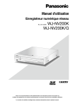
Operating Instructions
Network Disk Recorder
Model No.
WJ-NV200K, WJ-NV200VK
WJ-NV200K/G
(This illustration represents WJ-NV200VK.)
Before attempting to connect or operate this product,
please read these instructions carefully and save this manual for future use.
The model number is abbreviated in some descriptions in this manual.
CONTENTS
About the face matching function............................. 45
Face matching alarm actions................................ 45
Reset face matching alarm .................................. 46
Display the face matching thumbnail again.......... 46
Start/stop face matching actions manually........... 47
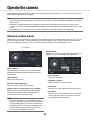
Operate the camera.................................................. 48
Camera control panel............................................ 48
Panning/Tilting...................................................... 49
Zooming................................................................ 50
Move to home position......................................... 50
Focus adjustment.................................................. 50
Iris (brightness) adjustment................................... 51
Auto mode............................................................. 51
Register camera preset positions......................... 52
Move camera preset positions.............................. 52
Register home position......................................... 53
Execute auto back focus....................................... 53
Set up mask areas................................................. 54
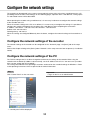
Configure the network settings................................. 55
Configure the network settings of the recorder.... 55
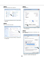
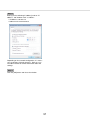
Configure the network settings of the PC............. 55
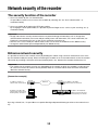
Network security of the recorder............................... 58
The security function of the recorder.................... 58
Enhance network security..................................... 58
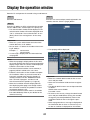
Display the operation window................................... 60
About the operation window..................................... 61
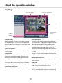
Top Page............................................................... 61
Control panel......................................................... 62
Camera selection panel......................................... 63
Setup panel........................................................... 64
Status display area................................................ 65
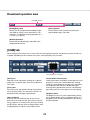
Download operation area...................................... 66
[CAM] tab.............................................................. 66
[HDD] tab............................................................... 67
Monitor live images from cameras............................ 68
Display images on a 1-screen............................... 68
Display images on a 4-screen (multiscreen).......... 69
Play recorded images................................................ 70
Play image recorded at a designated date & time.... 72
Search and play recording events
(REC event search).................................................... 73
Motion detection search and playback
(VMD search)............................................................. 75
Check a list of copied recorded images.................... 77
Event function........................................................... 79
Event action........................................................... 79
Cancel the alarm action........................................ 80
Cancel the error action.......................................... 80
Copy recorded images.............................................. 81
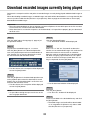
Download recorded images
currently being played............................................... 83
Preface........................................................................ 4
About the user manuals.......................................... 4
System requirements for a PC................................ 4
Trademarks and registered trademarks.................. 5
Abbreviations.......................................................... 5
Restrictions when using this product...................... 6
Before using this product............................................ 7
Face matching function........................................... 7
Motion detection (VMD) function............................ 7
Time display of recorded images............................ 7
Response to the mouse operations........................ 7
Black screen displayed when playing recorded
images..................................................................... 8
Recording operation................................................ 8
Event type............................................................... 8
Use an SD memory card............................................. 9
Operation window..................................................... 11
Ctrl (control) screen display................................... 11
Live monitor (monitor for display of live images
only)....................................................................... 15
Basic operation......................................................... 16
Display the setup menu......................................... 17
Logout................................................................... 17
Login operation at startup......................................... 18
Monitor live images................................................... 19
Operation panel..................................................... 19
1-screen display (control screen only)................... 20
Display camera images on a full screen
(wide view)............................................................. 21
Display or hide the camera title............................. 24
Use digital zoom (control screen only).................. 24
Record images.......................................................... 25
Record images (schedule recording)..................... 25
Play recorded images................................................ 26
Playback operation panel...................................... 26
Play images from a designated point........................ 28
Play image recorded at a designated
date & time............................................................ 28
Play the latest recorded image.............................. 29
Playback by designating a timeline....................... 30
Search and play......................................................... 32
Play images selected from logs (log search)......... 32
Search and play recorded images triggered by
motion detection (VMD search)............................. 33
Play back copied images.......................................... 36
Event function........................................................... 37
Event action........................................................... 37
Stop buzzer beeping............................................. 38
Cancel the alarm action........................................ 39
Cancel the error action.......................................... 39
Copy recorded images.............................................. 40
Format SD memory card....................................... 44
2
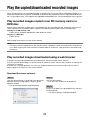
Play the copied/downloaded recorded images........ 85
Play recorded images copied on an SD memory
card or a DVD disc................................................ 85
Play recorded images downloaded using a web
browser................................................................. 85
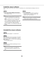
Install the viewer software..................................... 86
Uninstall the viewer software................................ 86
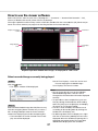
How to use the viewer software............................ 87
Operate the camera.................................................. 90
Panning/Tilting...................................................... 90
Zooming................................................................ 90
Focus adjustment.................................................. 91
Iris (brightness) adjustment................................... 91
Register preset positions...................................... 91
Move to preset positions....................................... 91
Auto functions....................................................... 92
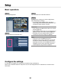
Setup......................................................................... 93
Basic operations................................................... 93
Configure the settings........................................... 93
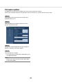
Firmware update................................................... 94
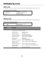
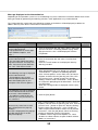
Notification by e-mail................................................ 95
Alarm mail............................................................. 95
Warning mail.......................................................... 95
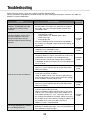
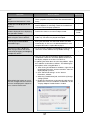
Troubleshooting......................................................... 96
Glossary.................................................................... 99
3
Preface
The network disk recorders WJ-NV200K, WJ-NV200VK and WJ-NV200K/G (hereinafter, recorders) are designed
for use within a surveillance system, and record images/audio from up to 16 network cameras (hereinafter, cameras) on the hard disk drives. Up to 16 cameras can be registered.
This recorder supports HDMI (High-Definition Multimedia Interface) standard which allows displaying playback/
live images with superior quality when connecting to a high-definition monitor using an HDMI cable (option). It is
possible to operate cameras from this recorder to display images from multiple cameras or switch cameras
from which images are to be displayed, etc.
The recorders described in this installation guide are the models that are compatible as of February, 2012.
Contact your dealer for further information.
* No hard disk drive is supplied with this recorder. For purchasing the hard disk drive, contact your dealer.
About the user manuals
There are 4 sets of operating instructions for the WJ-NV200K, WJ-NV200VK, WJ-NV200K/G as follows.
Installation Guide: Contains descriptions of how to install/connect this product and how to
configure the required settings.
Operating Instructions (PDF)
(this document): Contains descriptions of how to operate this product.
(Both operations using the interface on the product and using a PC via a
network are provided)
Quick Reference Guide: Contains descriptions of how to operate functions frequently used.
Operating Instructions of Additional
Business Intelligence Kit (PDF):Contains descriptions of how to use WJ-NVF20 (option), WJ-NVF20E
(option) on trial, how to register the license, how to configure the settings
and how to operate.
Adobe® Reader® is required to read the PDF files on the provided CD-ROM. When Adobe® Reader® is not
installed on the PC, download the latest Adobe® Reader® from the Adobe web site and install it.
Depending on descriptions, the model name of this recorder may be omitted as "NV200" in the manuals and on
the setup.
The screens used in these operating instructions show the case in which WJ-NV200VK is used and 16 cameras
are connected.
Refer to "readme.txt" on the provided CD-ROM for further information about the dedicated software (option)
that receives and displays the event and error information, compatible cameras and their versions.
System requirements for a PC
It is recommended to operate this product using a PC that meets the following system requirements.
OS:
Microsoft® Windows® 7*
Microsoft® Windows Vista®
Web browser:
Windows® Internet Explorer® 9.0 (32-bit)
Windows® Internet Explorer® 8.0 (32-bit)
Windows® Internet Explorer® 7.0 (32-bit)
CPU:
Intel® Core™ 2 Duo 2.66 GHz or faster
Memory:
1 GB or more
Monitor:
1 024 x 768 pixels or more, 24-bit True color or better
Network interface:
10BASE-T/100BASE-TX/1000BASE-T 1 port
Audio:
Sound card (When using the audio function)
Others:
CD-ROM drive: It is necessary to refer to the operating instructions on the provided
CD-ROM.
DirectX® 9.0c or later
4
Adobe® Reader®: It is necessary to refer to the operating instructions on the provided
CD-ROM.
* Windows® XP compatibility mode is unavailable.
Important:
• If using a PC that does not meet the above system requirements, it may cause problems such as slow imaging or the browser becomes inoperable.
• Microsoft® Windows® 7 Starter and Microsoft® Windows Vista® Starter are not supported.
Note:
• Refer to "Notes on Windows Vista® / Windows® 7" (PDF) for further information about system requirements
for a PC and precautions when using Microsoft® Windows® 7 or Microsoft® Windows Vista®.
• For information on the operation verification of the supported operating systems and web browsers, refer to
our website at http://panasonic.net/pss/security/support/index.html.
Trademarks and registered trademarks
• Adobe, Acrobat Reader and Reader are either registered trademarks or trademarks of Adobe Systems
Incorporated in the United States and/or other countries.
• Microsoft, Windows, Windows Vista, Internet Explorer, ActiveX, and DirectX are either registered trademarks
or trademarks of Microsoft Corporation in the United States and/or other countries.
• Microsoft product screen shot(s) reprinted with permission from Microsoft Corporation.
• Intel and Intel Core are trademarks or registered trademarks of Intel Corporation in the United States and
other countries.
• HDMI, the HDMI logo and High-Definition Multimedia Interface are trademarks or registered trademarks of
HDMI Licensing LLC in the United States and other countries.
• SDHC Logo is a trademark of SD-3C, LLC.
• All other trademarks identified herein are the property of their respective owners.
Abbreviations
The following abbreviations are used in this manual.
Microsoft® Windows® 7 Professional (32-bit) is described as Windows 7.
Microsoft® Windows Vista® Business SP1 (32-bit) is described as Windows Vista.
Windows® Internet Explorer® 9.0, Windows® Internet Explorer® 8.0 and Windows® Internet Explorer® 7.0 are
described as Internet Explorer.
SDHC/SD memory card is described as SD card or SD memory card.
Network cameras are described as cameras.
5
Restrictions when using this product
When using this product, some functions have the following restrictions. Before using this product, keep the
following in mind.
When displaying live images from the
camera
When recording images
• Black screen may be displayed for the first several
seconds (*) when the following operations are performed while displaying live images.
• When live images are displayed (by switching
camera, etc.)
• When image is zoomed in or out
• The actual time of recording trigger (event occurrence time, start time of the schedule recording,
etc.) and the recording start time (time displayed
on the recording event list) may not exactly be the
same.
• When pre-event recording is set to be performed,
pre-event recording duration may be longer than
the set duration.
When playing recorded images
When copying images
• First several seconds (*) may be skipped when the
following operations are performed while playing
recorded images.
• When cameras are switched
• When image is zoomed in or out (When operating to zoom in/out a paused recorded image,
image of several seconds later than the displayed image may be zoomed in.)
• When the playback button is clicked again
while playing images
• When the first frame is displayed by starting
the frame by frame playback during pausing
• Playback may be performed in several seconds
intervals (*) when the following operations are performed. Refer to the description of operations
during playback on pages 26 and 71 for how to
control playback.
• Reverse playback
• Fast playback/Fast reverse playback
• Reverse frame playback
• When playing images by designating date & time,
playback may start from a point several seconds
(*) before/after the specified time or from the first
frame of the next record.
• When searching for the latest recorded images,
the starting point of playback is around 30 seconds before the date & time of the latest recorded
images. However, it may not start exactly.
• When the frame rate is set to 30 ips, recorded
images may not be played smoothly.
Copying of recorded images may start from a point
several seconds (*) before the designated start time
when copying recorded images.
When downloading recorded images
Downloading of recorded images may start from a
point several seconds (*) earlier than the designated
start time.
* Time (seconds) differs depending on the refresh
interval setting of the camera (0.2 - 5 seconds).
To shorten time lag, set the refresh interval of the
camera shorter.
Refer to the operating instructions of the camera
for information about the refresh interval setting.
When using an SD memory card
If operations are performed soon after an SDHC/SD
memory card is inserted, it may take time to recognize the media.
6
Before using this product
Face matching function
Face recognition refers to a function that uses a connected camera supporting this function to detect facial features of people and matches them against similar facial features recorded earlier or contained in live images.
The matching accuracy varies depending on installation, settings and adjustment of the camera, ambient environment and object. Matching of facial features may therefore not work under the following conditions:
• When illumination is not uniform, for example, outdoors
• When the face is partially concealed (mask, sunglasses, helmet, etc.)
• When the face is not facing the camera
• When a subject is moving very fast
• Under the influence of strong external light (such as the headlights of a car, rising sunlight or setting sunlight)
* Configure the settings of the camera supporting this function before attempting to use the face matching
function.
Motion detection (VMD) function
The motion detection (VMD) function of cameras detects motions referring to changes of luminance (brightness)
in areas set in advance.
The motion detection function will not effectively work in the following situations or may sometimes be malfunctioning.
• When there is a very little difference in luminance (brightness) between a background and a subject
• When brightness of images is low such as at night
• When a subject moves very slow
• When a subject is very small
• When the amount of rays of light incidence changes frequently such as at a window or outdoors.
• When light such as sunlight or car headlight comes from outside
• When a fluorescent lamp flickers
• When a subject has depth
When configuring the motion detection settings, check the function performance both in daytime and at night
after appropriately configuring the area settings and the sensitivity settings according to the camera installation
conditions and possible movement of subjects. When the detection function does not work or false detection
occurs, use a sensor separately. Refer to the operating instructions of the camera for further information.
Time display of recorded images
When displaying recorded images, the displayed date & time may sometimes skips. This is not malfunction.
The displayed date & time on the monitor and the recorder may sometimes not be exactly the same. This is also
not malfunction.
Response to the mouse operations
While this recorder is processing multiple operations at the same time, the response to the operations from the
connected mouse may temporarily become slow. This is not malfunction.
7
Black screen displayed when playing recorded images
In the following cases, a black screen may be displayed during playing recorded images. However, this is not
malfunction.
• When changing cameras or screen patterns during playback or pausing
• When skipping/reverse skipping during playback
• When fast forwarding/reverse fast forwarding during playback
• When the latest recorded image is played while displaying images on a multiscreen
• When going to the next recording event list by fast forwarding/reverse fast forwarding or skipping/reverse
skipping during playback
• When playback operation is affected by another operation (such as when receiving multiple alarms sequentially or while copying is being performed simultaneously)
Recording operation
It is possible to connect up to 16 cameras to the recorder and record images from them on the hard disk drives.
The following recording operations are available.
Schedule recording:Recording that is automatically performed at the designated time range on the designated day(s) of the week
Event recording:Recording that is automatically performed when an event occurs (such as terminal
alarm/camera site alarm, etc.)
Important:
• Recording may not be performed for around 3 seconds in the following cases. However, this is not a malfunction.
• When the settings are changed and the setup menu is closed during recording
• When the resolution, image quality or the frame rate is changed during recording
• When event recording starts or ends during recording
Event type
The following event recording types are displayed in list form on the web browser:
SCH: Schedule recording
The following are detailed event recording types.
COM: Displayed when a command alarm occurred
TRM: Displayed when a terminal alarm occurred
SITE: Displayed when a camera site alarm occurred
FACE Displayed when a face matching alarm occurred
PRE: Pre-event recording
8
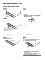
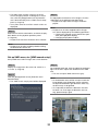
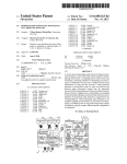
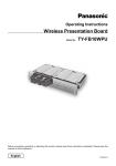
Use an SD memory card
Insert an SD memory card (option)
Step 1
Step 3
Open the SDHC/SD memory card slot cover.
Close the SDHC/SD memory card slot cover.
Note:
• When removing the SD memory card from the
slot, push the card until it clicks and pull it out
straight.
• When pulling out the SD memory card, hold both
edges with your fingers.
Pull the tab
down.
SDHC/SD memory
card slot cover
Step 2
Insert a SD memory card to the slot until it clicks.
Hearing a click means that the card is properly inserted.
• The SDHC/SD memory card slot cover is
designed to come off when an excessive force is
applied. In this case, attach the slot cover to the
original position.
When inserting an SD memory card,
confirm that the label on the SD
memory card is upside and only the
upper right corner of the card has
different shape.
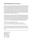
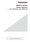
Insert a DVD disc (commercially available, only for WJ-NV200VK)
Step 1
Step 2
Open the DVD drive cover.
After confirming that the power of the recorder is on,
press the eject button located at the center of the
DVD drive and pull the disc tray gently.
DVD drive cover
Pull the tab down.
Eject button
Note:
• After copying the recorded data on a disc, perform finalization (the procedure to eject the DVD)
to enable play-back on a PC. (☞ Operating
Instructions (PDF))
If the disc is not finalized, the tray may not open
even after the eject button is pressed.
9
Step 3
Place a disc with the label side up and fit the hole of
the disc to the center (spindle) of the tray. Then, push
the tray gently. Click sound will be heard and the disc
will fit in the tray.
Spindle
Step 4
Push the tray to the end. Click sound will be heard
and the tray will be fixed.
Step 5
Close the DVD drive cover.
Important:
• When opening/closing the DVD drive tray, do not
apply force on the tray.
• When not using the DVD drive, close the disc tray.
• When removing the disc from the tray, hold the
spindle to detach the disc. If trying to detach the
disc forcibly, it can damage both the disc and the
DVD drive.
10
Operation window
The recorder can be operated using the provided mouse connected to the mouse connection port on the front
side of the recorder. When operating the recorder using a web browser, refer to "Configure the network settings" (☞ page 55).
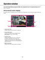
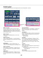
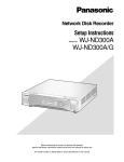
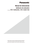
Ctrl (control) screen display
The control screen is the default screen at startup. The main operations of the recorder are performed from this
screen.
q
e
w
r
q Image display area
Displays images from the camera. (☞ Page 19)
w Status display panel
Displays the statuses of the recorder. Also displays alarm/error status and remedies.
(☞ Page 14)
e Operation panel
Used to switch between screens, to play back
recordings, operate the camera and so on.
Displays the current date & time. While daylight
saving time is activated, the time will be displayed
with an asterisk (*).
r [Wide view] button
Switches the main monitor to wide view display.
11
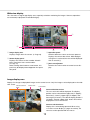
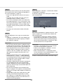
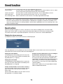
Wide view display
This view offers a large image display area, especially suited for monitoring live images. However, operations
are restricted (no playback of recorded images).
q
w
e
q Image display area
Displays images from the camera. (☞ Page 19)
r
e Operation panel
Switches between screens and screen patterns.
Displays the current date & time. While daylight
saving time is activated, the time will be displayed
with an asterisk (*).
w Status display panel
Displays the statuses of the recorder. Also displays alarm/error status and remedies.
(☞ Page 14)
When clicking alarm button or error button, this
panel may be displayed overlapped on the operation panel.
r [Ctrl screen] button
Switches the main monitor to control screen display.
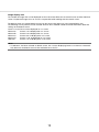
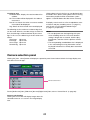
Image display area
Displays live images and playback images on the control screen. Only live images can be displayed on the wide
view screen.
Camera selection
frame
Date & time
Camera title
Camera title/date & time
The set camera title will be displayed. The display
position can be selected from upper-left ("L-Upper"),
lower-left ("L-Lower"), upper-right ("R-Upper") and
lower-right ("R-Lower"). The default display position is
"R-Upper". (Default: Upper right). Date & time will be
displayed as set on the camera.
12
Camera selection frame
Displays the camera being operated. When using
1-screen/4-screen display (☞ pages 20 and 21), the
cameras can be operated with the mouse.
Image display area
The number of images that can be displayed on the multiscreen differs for the control screen and the wide view
screen. Playback of images on a 16-screen is not possible while working with the control screen.
The default screen on startup (default screen) can be set for each login user in the image display area.
The following screen patterns can be selected. Refer to the Installation Guide for further information about the
settings of the default screen.
Camera 1 to 16: Each camera displayed on a 1-screen
4Screen-A:
Camera 1 to 4 displayed on a 4-screen
4Screen-B:
Camera 5 to 8 displayed on a 4-screen
4Screen-C:
Camera 9 to 12 displayed on a 4-screen
4Screen-D:
Camera 13 to 16 displayed on a 4-screen
16Screen:
Camera 1 to 16 displayed on a 16-screen
Note:
• If "16Screen" has been selected as default screen, the 4-screen displaying Camera 1 to Camera 4 automatically becomes the default screen of the web browser on the PC.
13
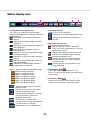
Status display panel
Normal operation
w
e
In case of alarm/error (When the associated buttons are displayed)
r
q
w
i
t
o
e
y
u
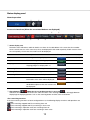
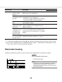
q Status display area
Recorder status indications and their details are shown in the table below. In the event that the recorder
enters several statuses at the same time, these are displayed in their order of priority. If both statuses have
the same priority, the one that occurred last will be displayed.
Status
Description
Example
Priority
Live
Live images are being displayed.
5 (Low)
Playback
Recorded images are being played.
5
Copying
Data is being copied.
Copying progress is displayed in %.
4
Formatting SD
SD memory card is being formatted.
4
Finalizing DVD
The DVD disc is being finalized to eject.
4
Formatting HDD
HDD is being automatically formatted.
3
In the alarm state
Indicates an alarm occurrence. Detailed
information of the alarm will be displayed.
2
In the error state
Indicates that an error has occurred. A
detailed description of the error content will
be displayed.
1 (High)
(When the face matching function is not used:
)
w Alarm buttons
Indicate that an alarm has occurred. Turn red in the alarm state. Clicking the buttons will toggle between
displaying/not displaying buttons such as the alarm log button and the alarm reset button.
<Face matching function>
If the face matching function has been configured for use, the following display functions and operations are
available:
Face matching stopped and Face matching alarm off
Face matching stopped and Face matching in alarm state
Face matching in operation and Face matching alarm off
Face matching in operation and Face matching in alarm state
14
e Error button
Indicates that an error has occurred. Turn yellow in the error state. Clicking the buttons will toggle between
displaying/not displaying buttons such as the error log button and the error reset button.
r Alarm log display button
The alarm logs are displayed on the operation panel of the control screen.
Up to 750 error logs are saved. When more than 750 logs are filed, the older logs will be overwritten by the
newer logs. In this case, the oldest log is the first to be overwritten.
t Alarm reset button
Cancels the alarm action. Clickable only in the alarm state.
y Error log display button
The error (trouble) logs are displayed on the operation panel of the control screen.
Up to 1000 error logs are saved. When more than 1000 logs are filed, the older logs will be overwritten by
the newer logs. In this case, the oldest log is the first to be overwritten.
u Error reset button
Cancels the error (trouble) action. Clickable only in the error state.
i Face matching start/stop button
Starts/stops face matching actions manually. Face matching will resume when this button is clicked during
pause. Face matching will stop when this button is clicked during face matching actions.
o Face display (Thumbnail) button
The latest face matching results are displayed on the operation panel of the control screen. (☞ Page 45)
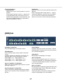
Live monitor (monitor for display of live images only)
Important:
• Configuration and operation of the recorder from the live monitor is not possible.
Live images from a camera set up in advance can be displayed on a 1-screen on the live monitor. When several
cameras are selected, camera images will be switched sequentially at the selected switching interval (sequence
display). In addition, camera images can be switched according to the signal input triggered by a terminal
alarm. (☞ Installation Guide)
Note:
• Multiscreen display is not possible.
• The camera title and date & time are not displayed on the live screen.
• The date & time and camera also appear on the camera image displayed on the live monitor, but some characters may be cut off.
• To display images, it is necessary to select the cameras to be displayed in the setup menu in advance. The
recorder is not configured to display camera images by default.
• Depending on the selected switching interval, a black screen may appear before camera images are displayed.
• When the secret view function is selected, the single screen on the main monitor or selected images on a
multiscreen will not be displayed.
• While the sequence display is being performed, the secret view images will be skipped (not displayed).
• The image of a camera where an error has occurred will not be displayed.
• The size of displayed images will be fit into the screen regardless of the aspect ratio.
15
Basic operation
To operate, use the mouse connected to the recorder to move the mouse cursor displayed on the main monitor
and left-click the buttons or tabs displayed on the screen. (Hereinafter, "Left-click..." will be described as
"Click..." in this document.)
In lines where the [D]/[C] buttons are displayed, the value on which the cursor is placed can be changed by
turning the mouse wheel. For example, when setting date & time, the hours, minutes and seconds can be
changed.
The shape of the mouse cursor will change as follows depending on the display screen and mouse operation.
:Normal operation
:When dragging a camera number panel (wide view screen)
Note:
• When no operation is made for 10 seconds or more, the mouse cursor will be hidden. The mouse cursor will
be displayed again when the mouse is moved.
• It is impossible to connect a mouse to the mouse connection port if the connector from the mouse is upside
down. When it is hard to connect, check the upside down position of the connector from the mouse.
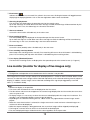
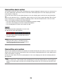
About the operation of on-screen keyboard
Setting items can be entered using the on-screen keyboard. When clicking the [
] icon beside the entry field,
the on-screen keyboard will be displayed, and it will become possible to enter characters by clicking the character keys on the keyboard.
Entry field
Language selection pull-down menu
Click the [C] button to select the language for
character entry.
[Del all] button
Deletes all the characters in the entry field.
[Delete] button
Deletes a character pointed by the cursor in the entry
field.
[←]/[→] button
Move the cursor in the entry field to either direction.
[A/a] button
This button changes the characters to be entered
between capital letters and small letters.
16
[Next] button
Changes the keys to be displayed for character entry.
The displayed keys are changed as follows:
Keys for the language selected by the language
selection pull-down menu → Combination characters
→ Special characters
[Enter] button
Determines the entered characters and closes the onscreen keyboard.
Note:
• Basic operations are also applied to the "Login"
window and the window for entering a password.
• Click the [×] button to close the window without
determining the entered characters.
• Depending on the windows for character entry
such as the camera title, capital letters may be
displayed on the on-screen keyboard instead of
small letters.
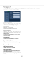
Display the setup menu
Click the [Setup] button.
→ The setup menu will be displayed. For certain user levels, the login window will be displayed.
Refer to the Installation Guide for further information about the settings.
Note:
• If changes are made to the setup and the setup menu is closed while recording is underway, recording will
be interrupted for around 3 seconds.
• When changes are made to the setup, all users logged into the recorder will be forcibly logged out.
Logout
Click the [Logout] button. To log out, click the [OK] button in the confirmation window displayed.
Note:
• When "On" is selected for "Auto login" (☞ Installation Guide), the user will not be logged out even when the
[Logout] button is clicked.
17
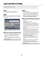
Login operation at startup
When "Off" is selected for "Auto login" (☞ Installation Guide), the recorder will start up in the logged-out state
after completing the system check.
When the operation window is displayed on the main monitor, enter a user name and password as follows:
Step 1
Step 3
Click the [Login] button on the operation screen.
→ The "Login" window will be displayed.
Click the [OK] button.
→ When the entered user name and password are
correct, the login window will disappear and the
login button will change to the logout button.
When the entered user name and password are
incorrect, the error window will be displayed.
Close the error window and log in again.
Step 2
Enter a user name and password. For character entry,
refer to "About the operation of on-screen keyboard"
(☞ page 16).
Note:
• The default administrator name and password are
as follows.
Administrator name: ADMIN
Password: 12345
• To enhance the security, change the default
administrator name and password before running
the recorder. Change the password periodically.
Refer to the Installation Guide for how to change
the password.
• To log out, click the [Logout] button on the operation screen.
• When a user logs out or when auto logout is activated during copying, the copying will be canceled. (When operating the recorder using a web
browser, it will take around 90 seconds until copying is stopped after the web browser is closed.)
• Displaying images in the logged-out state
After startup with "Auto login" set to "Off", the
"4Screen-A" will be displayed.
When logging out during the login process, the
same screen as right before logout will be displayed.
(Which camera images the user is authorized to
display depends on the user level set up.)
• When "On" is selected for "Auto login", it is
unnecessary to perform the operations described
on this page.
• Refer to the Installation Guide for how to register
users.
Note:
• When "On" is selected for "Quick login", the user
name can be selected from the pull-down menu.
The password entered will be displayed as "*"
marks.
• When a user tries to operate an unauthorized
function in the logged-out state, the login window
will be displayed.
18
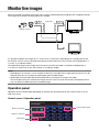
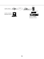
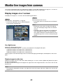
Monitor live images
When the recorder started up, live images from cameras will be displayed according to the configured settings.
Live images from cameras are displayed via the recorder.
Image data
Network cameras
Main monitor
Recorder
Live monitor
It is possible to display live images on a 1-screen or on a multiscreen. Depending on the configuration of the
live monitor, cameras can be switched automatically and the respective camera image can be displayed on a
1-screen. (☞ Installation Guide)
The audio will be output when images from the camera to which the audio is assigned are displayed on a
1-screen or a multiscreen on the main monitor. (☞ Installation Guide)
Note:
• Depending on the camera in use or network environment, the audio of live images from the camera may be
delayed, but that may not affect the audio output from recorded images.
• Update processing of audio data will be performed to synchronize live images with audio.
Due to the processing, the audio of live images from the camera may be momentarily interrupted, but that
may not affect the audio output from recorded images.
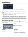
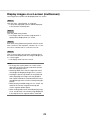
Operation panel
Operations with live images differ depending on whether they are performed on the control screen or on the
wide view screen.
Control screen / Operation panel
Camera number panel
Multiscreen buttons
Digital zoom buttons
Mute button
19
Camera number panel
The camera number panel shows all camera-related
information, such as registration status, camera title
and recording status.
Camera number:
(Character color)
White: Camera is registered.
Gray: Camera is not registered.
(Background color)
Aqua: Image display area is displaying images
Blue: Camera is registered and image display
area is not displaying images.
Gray: Recording is not possible or camera is
not registered.
Camera title: Shows the first 8 characters of the previously entered camera title.
(Character color)
Same as camera number
(Background color)
Red: In the alarm state
Gray: Camera is not registered.
Recording indicator: Lights red when recording is
] indicates a
being performed. Display of [
connection error.
Multiscreen buttons
The 1-screen/4-screen/16-screen buttons are displayed.
Digital zoom buttons
When displaying images on a 1-screen or 4-screen,
the images can be enlarged/reduced (☞ page 24).
Mute button
Each click of this button toggles between mute and
mute cancel of the camera audio.
1-screen display (control screen only)
To display live images on a 1-screen, take the following procedures.
Displaying images on a 1-screen
Step 1
Note:
• Another way to display images on a 1-screen is to
double-click the camera number panel of the
camera to be selected in the image display area.
• In the multiscreen display area, double-clicking
the camera selection frame is also possible to display an image on a 1-screen.
• The audio of the camera whose images are being
displayed will be output.
• At the default, black zones will be displayed on
the top and bottom of images with the aspect
ratio of 16:9. Refer to the Installation Guide for the
setting to enlarge the vertical size of displayed
images.
Click the camera number panel of the desired image
from the camera.
→ The background color of the selected camera
number will turn aqua, and live images will be displayed.
Displaying images on a multiscreen
Step 1
Click the 1-screen button for the screen pattern of
multiscreen.
→ The image display area will be displayed on a
1-screen.
Step 2
→ The background color of the selected camera
number panel will turn aqua, and live images will
be displayed.
20
Display images from cameras on a multiscreen (control screen)
Live images from cameras can be displayed on a multiscreen (4-screen, 16-screen).
• The audio of the selected camera will be output.
• In case of 9 camera licenses, cameras will be
switched as follows by clicking the 4-screen button:
Camera 1 to 4 → camera 5 to 8 → camera 9
(image displayed in the top left segment only) →
camera 1 to 4
• At the default, black zones will be displayed on
the top and bottom of images with the aspect
ratio of 16:9. Refer to the Installation Guide for the
setting to enlarge the vertical size of displayed
images.
Step 1
Click the 4-screen or 16-screen button.
• 4-Screen button
Each click of a button switches to the next 4
screens in the sequence: camera 1 to 4 →
camera 5 to 8 → camera 9 to 12 → camera 13 to
16.
• 16-Screen button
The images of camera 1 to 16 will be displayed.
→ Live images from cameras will be displayed on a
multiscreen.
Note:
• After having switched from multiscreen to
1-screen display, double-clicking the image display area will display the multiscreen displayed
before switching screens.
• It is also possible to switch the images displayed
on the 4-screen by clicking the camera number
panel with the 4-screen displayed. (When the
panel of camera 5 is clicked with the 1- to
4-screen displayed, the images of camera 5 to 8
will be displayed)
Display camera images on a full screen (wide view)
Camera images will be displayed in wide view on a multiscreen. Screen patterns to display images can be
switched by clicking the Multiscreen buttons.
Step 1
Step 2
Click the [Wide view] button (☞ page 11) on the operation window.
→ Images from the camera will be displayed on a full
screen. The 3-screen is displayed by default.
To return from the full screen to the control screen,
click the [Ctrl screen] button.
→ The display reverts to the control screen. The
image display area corresponds to the default
screen set up by the login user.
Note:
• Clicking the [Wide view] button again will switch
to the multiscreen displayed before.
21
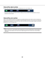
Wide view operation panel
Camera number panel
Multiscreen buttons
When the screen segments are not equally divided by
the setting (Default)
Camera number panel
The camera number panel shows all camera-related
information, such as registration status, alarm status
and recording status.
Camera number [CAM]:
(Character color)
White: Camera is registered.
Gray: Camera is not registered.
(Background color)
Aqua: Image display area is displaying images
Blue: Camera is registered and image display
area is not displaying images.
Gray: Recording is not possible or camera is
not registered.
Alarm display [ALM]: The background turns red in the
alarm state.
Recording indicator [REC]: Lights red when recording
is being performed.
Multiscreen buttons
When the screen segments are equally divided by the
setting (4:3)
Multiscreen buttons
When the screen segments are equally divided by the
setting (16:9)
Multiscreen buttons
Screen pattern buttons
The screen pattern buttons will be displayed as follows.
Note:
• RefertotheInstallationGuideforthesettingto
determine whether or not to divide the screen
segments equally.
22
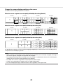
Change the camera display position on the screen
The default camera display positions are as follows:
When the screen segments are not equally divided by the setting (Default)
3-screen
3-screen
1
1
6-screen
2
2
3
3
1
1
4
4
9-screen
6-screen
2
2
5
5
3
3
6
6
9-screen
1
1
4
4
2
2
5
5
16-screen
3
637
8
6
8
9
7
9
16-screen
2
3 4
5 6
1
2
3 7
4
8
9
10
5
6
7
1
11 12 13 14
16
8 15
9 10
11 12 13 14 15 16
When the1-screen
screen segments are equally
(4:3)
12-screen
4-screendivided by the setting
1-screen
1
1
3
3
1
1
16-screen
4
6
4
3 8
2 7
11
10
8
6 7 12
16
15
14
10 11 12
13 14 15 16
1
5
1
9
5
13
9
1 12-screen
2 3 4
4-screen
2
2
4
4
1
5
2
6
3
7
4
8
5
9
6 11
7 12
8
10
9
10 11 12
16-screen
2 3
When the screen segments are equally divided by the setting (16:9)
1-screen
1
4-screen
1
3
9-screen
2
4
16-screen
1
2
3
4
5
6
7
8
9
1
2
3
4
5
6
7
8
9
10
11
12
13
14
15
16
It is possible to change the camera image by dragging & dropping the number of the camera number panel (1
to 16) onto the desired display position.
Note:
• Whenacameraisassignedtoascreensegmenttowhichanothercameraisalreadyassigned,theimageof
the camera originally assigned to that position will disappear.
• Theassignedcamerapositionisretainedeveniftherecorderisrebooted(notehoweverthatinitializingthe
settings will also reset the camera positions to the defaults).
• Theaudioofthecameraassignedtothetopleftpositionwillbeoutput.
• If"Mute"wasselectedonthecontrolscreen,noaudiowillbeoutput.
• Thesizeofdisplayedimageswillbefitintothescreenregardlessoftheaspectratio.
23
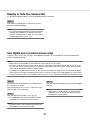
Display or hide the camera title
It is possible to display/hide the camera title displayed on the monitor.
Step 1
Each time the [OSD] button is clicked, the camera
title will be displayed/hidden.
Note:
• The setting to display/hide the camera title will be
retained until the power is turned off. Once the
power is turned off and on again, the camera title
will be displayed on system start.
Use digital zoom (control screen only)
Images on the 1-screen and 4-screen can be digitally zoomed. It is also possible to move the zoomed area
within the displayed image.
Note:
• Digital zoom is not available on the wide view screen and on the 16-screens.
• To use this function on the 4-screen, do so after first selecting the desired camera image. To select a camera, click the camera number panel or the camera image. Once a camera has been selected, the selection
frame will be displayed around the camera image.
• If "Enable camera control with mouse" on the camera control panel (☞ page 48) is not checked, the digital
zoom factor can also be changed by placing the cursor on the image in the image display area and turning
the mouse wheel. In this case, the point where the mouse cursor is positioned will become the zoom center.
Step 1
Step 3
Confirm that the image display area is displayed on
the 1-screen or 4-screen.
(when displaying on the 4-screen, select the camera
whose image is to be zoomed)
Click the digital zoom button [x1] to cancel the digital
zooming.
Note:
• Digital zoom is automatically canceled by other
operations such as selecting another camera or
changing the screen pattern.
Step 2
Click the digital zoom buttons [×2] [×4] [×8].
→ The displayed image will be enlarged x2/x4/x8
centering on the center point of the screen.
Note:
• Clicking a point in the zoomed image makes the
clicked point the center of the image.
24
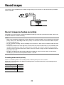
Record images
Live images can be recorded on the recorder. Images from up to 16 cameras can be simultaneously recorded
with this recorder.
Network cameras
Image data
HDD
Recorder
Record images (schedule recording)
Recording can be automatically started and stopped according to a previously specified schedule. Refer to the
Installation Guide for schedule recording.
Note:
• When event recording is triggered by an alarm during the schedule recording, event recording has the higher
priority. Refer to the "Recording mode and its priority" section below for further information about the priority of the recording mode.
• To stop schedule recording, stop the recording on the setup menu. Refer to the Installation Guide for further
information.
• In case of a network error, the image of the camera where the communication error has occurred will not be
recorded. Recording starts when the network error is recovered. If the status in which the communication
with the camera is disconnected recovers within around 40 seconds, images will not be recorded and error
logs will not be saved.
• Schedule-recorded image data will be divided into multiple files every hour on the hour. In that moment,
recording may sometimes be interrupted around for 1 second.
Recording mode and its priority
There are 3 recording modes. The recording modes and their priority levels are as follows.
When two or more recordings with different recording modes started simultaneously, only recording with the
higher priority will start.
Recording mode
Priority
Event recording
1
Schedule recording
2
Pre-event recording
3
25
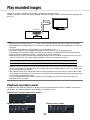
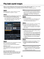
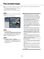
Play recorded images
Display the images recorded on the recorder’s hard disk on the main monitor.
Playback operation can be made while recording. Playback of images can be controlled from the operation display area.
Image data
Main monitor
HDD
Recorder
Note:
• When playing recorded images on a 1-screen, audio recorded together with these images will be output.
• When displaying recorded images on a multiscreen, audio from the camera to be displayed on a screen will
be heard.
• No audio will be output when playing back in fast forward/fast reverse.
• The camera image can be changed by clicking the camera number (1 to 16) during playback.
• The Multiscreen select button, digital zoom button, Mute button and OSD button remain effective during
playback. Refer to "Monitor live images" (☞ page 19) for further information.
• When displaying images recorded at the following setting values of resolution and frame rate on each segment of a multiscreen, the images will be played back with the selected refresh interval.
Resolution (Image capture size)
Frame rate
Display
SXVGA
15 ips, 30 ips
4-screen
• Different values selected for resolution and frame rate will cause the data size of the playback images on the
multiscreen to differ considerably, which may result in non-synchronized playback. In this case, pause and
then restart playback (☞ page 27).
• At the default, black zones will be displayed on the top and bottom of images with the aspect ratio of 16:9
when images are played back on the control screen. Refer to the Installation Guide for the setting to enlarge
the vertical size of displayed images.
• The size of displayed images will be fit into the screen regardless of the aspect ratio when images are
played back on a full screen.
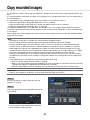
Playback operation panel
In playback mode, operation buttons are displayed on the playback operation panel. In addition to the operation buttons, the playback operation panel displays the playback status.
Normal status (during display of live images)
Image playback status
Playback pause status
26
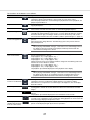
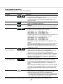
The functions of the buttons are as follows:
Function
Example
Operation
Playback button
Plays recorded images.
Clicking this button while playback is paused will cancel the pause status.
When the playback button is clicked during fast playback/fast reverse playback, the
playback speed will be x1.
Stop button
Playback will stop and live images will be displayed when this button is clicked during playback/pause.
Pause button
Playback will be paused when this button is clicked during playback.
Pause will be canceled when this button is clicked during playback/pause.
Captured image button
Saves images paused during playback on SD memory card.
Clickable only while playback is paused on a 1-screen. When this button is clicked,
the button will turn gray, and images will be saved. The SD memory card can be
removed when the button becomes available. ("About captured images" ☞ page 35)
Next image/
Previous image button
When the next image button is clicked during pausing, the next frame is played and
paused.
When the previous image button is clicked during a pause, the previous frame is
played and paused.
Note:
When playing H.264/MPEG-4 images, some frames of recorded images will not
be displayed. Reverse frame-by-frame playback will be performed with the
refresh interval setting of the camera.
Fast forward/
Fast reverse button
Playback speed of fast playback will be changed in the following order each time
the fast forward button is clicked:
Step2 (Approx. 2x) → Step3 (Approx. 4x) →
Step4 (Approx. 8x) → Step5 (Approx. 16x) →
Step6 (Approx. 32x) → Step7 (Approx. 48x)
Playback speed of fast reverse playback will be changed in the following order each
time the fast reverse button is clicked:
Step2 (Approx. 2x) → Step3 (Approx. 4x) →
Step4 (Approx. 8x) → Step5 (Approx. 16x) →
Step6 (Approx. 32x) → Step7 (Approx. 48x)
The playback speed will be displayed on the playback status display.
Note:
When playing H.264/MPEG-4 images, some frames of recorded images will not
be displayed. Except for x2 fast playback speed, fast playback/fast reverse
playback will be performed with the refresh interval setting of the camera.
Next record/
Previous record button
Clicking the next record button will play back the next later recording.
Clicking the previous record button will play back the next earlier recording.
When there is no next/previous recorded image to be skipped to, the current playback will continue.
[Go to last] button
When this button is clicked, playback of the latest recorded images will start. The
starting point is around 30 seconds before the date & time of the latest recorded
images.
Playback status display
The status of the recorder such as the playback status, pause status etc. will be displayed.
The playback speed will be displayed in fast forward/fast reverse mode.
Wide view button
When this button is clicked during playback, the recorded images will be displayed
on a full screen. Clicking the [Ctrl screen] button during playback on a full screen will
return the image display to the previous status.
Non-display button
(Displayed during playback on a full screen)
Hides the playback operation panel and the date & time operation panel. These
panels can be displayed again by the mouse operations.
27
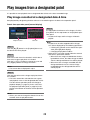
Play images from a designated point
It is possible to start playback from a designated date & time or the latest recorded image.
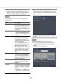
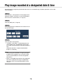
Play image recorded at a designated date & time
Start playback by designating the date & time of a recorded image on the date & time operation panel.
Date & time operation panel (normal display)
Step 4
To stop playback and return to live images, click the
[Live] button or the stop button on the playback operation panel.
→ Playback will stop, and live images will be displayed.
Playback button
Calendar
Note:
• Playback can also be stopped and live images
can also be displayed by the following operations:
• Clicking the [x] button on the date & time operation panel (playback display)
• Changing the playback medium
• When there is no image stored under the entered
date & time, proceed as follows:
• When there are images recorded after the designated date & time, the oldest image recorded
after the designated date & time will be played.
• When there are no images recorded after the
designated date & time, the newest image
recorded before the designated date & time
will be played.
Step 1
Click the [D]/[C] button in the [Playback] box to set
the date & time to be played.
Step 2
Select the month from the calendar in which date &
time of the image to play back is included.
Click the [<<Y]/[Y>>] button to change the year and
the [<M]/[M>] button to change the month.
Note:
• The current date is displayed in aqua.
Step 3
Click the date & time of the image to play back from
the calendar.
→ The frame around the selected date turns green,
and playback starts at the designated date & time.
The date & time operation panel will change to
playback display (☞ page 30). At the same time,
the playback operation panel (☞ page 26) is displayed at the bottom of the date & time operation
panel.
Note:
• Unless you want to change the date & time on the
calendar, click the playback button.
28
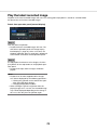
Play the latest recorded image
Playback of the latest recorded images will start. The starting point of playback is around 30 seconds before
the date & time of the latest recorded images.
Date & time operation panel (normal display)
Step 1
Click the [Go to last] button.
→ Playback of latest recorded images will start. The
date & time operation panel will change to playback display (☞ page 30). At the same time, the
playback operation panel (☞ page 26) is displayed
at the bottom of the date & time operation panel.
Step 2
To stop playback and return to live images, click the
[Live] button or the stop button on the playback operation panel.
→ Playback will stop, and live images will be displayed.
Note:
• Playback can also be stopped and live images
can also be displayed by the following operations:
• Clicking the [x] button on the date & time operation panel (playback display)
• Changing the playback medium
• When clicking the [Go to last] button while displaying images on a 4-screen, the recorded image
may not be displayed depending on the timing. In
this case, click the [Go to last] button again.
29
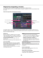
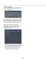
Playback by designating a timeline
When playback starts, the date & time operation panel will change to playback display.
This section explains how to use the timeline display to designate a playback date & time by operating the playback slider.
Date & time operation panel (playback display)
Scale selection button
Jump buttons
Display range selection
button
Playback slider
Display range selection
button
Timeline
The playback display shows available recorded images and displays these on a timeline sorted by type. It is
possible to change the type of recorded images displayed on the timeline, change the timeline scale, and designate the recorded image to play.
[REC Event]
Mark the checkboxes of different types of recorded
images and display them on a timeline. If changes are
made during playback, playback will be paused and a
new search will be performed.
Schedule: Schedule-recorded images will be displayed in pink
Event: Event-recorded images will be displayed in red
Note:
• To display the result of the motion detection
search, it is necessary to configure the settings of
the connected cameras that support the motion
detection search function in advance.
Refer to the "readme.txt" on the provided
CD-ROM about supported cameras. Refer to the
operating instructions of the camera in use for further information.
[Advanced setup] button
Display the advanced setup panel and change event
types and other information displayed on the timeline.
(☞ Page 31)
[Information/VMD]
When this box is checked, the time zone recorded
when the VMD function was activated (motion was
detected in an image) will be displayed in blue on the
timeline. (Playback will be paused.)
Periods for which no recorded images are available
will be displayed in black.
Scale selection button
Select a timeline display covering 2 hours (2 h), 8
hours (8 h) or 24 hours (24 h).
Display range selection button
The timeline will be displayed in accordance with the
setting of the scale selection button.
30
[Playback slider]
Displays the time during playback. Drag and drop the
playback slider to a desired time on the timeline to
start playback from that time.
buttons will move the playback point by the amount
of time specified under [Jump interval].
Available ranges: 1min/ 3 min/ 5 min/ 10 min/
15 min/ 30 min
Note:
• The playback slider may not soon move to the
desired position.
[Jump interval]/Jump buttons
Move the playback point by a given amount of time
and play back from that point. Clicking the [<] / [>]
[Playback of audio]
This item is displayed when the recorder is set up to
lock in a camera with audio output. If this checkbox is
marked, the audio associated with the displayed
image will be output. (☞ Installation Guide)
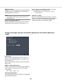
Change event types and other information displayed on the timeline [Advanced
setup]
[Event type]
Set event types to be displayed on the timeline. To
display event-recorded images on a timeline, mark
their checkboxes.
Refer to the Installation Guide for further information
about alarms.
[VMD sensitivity adjustment]
Set the sensitivity for the motion detection displayed
on the timeline. Sensitivity increases in the steps
shown below.
Low → Mid → High → All
[Back] button/[X] button
Click this button to return to the date & time operation
panel (playback display).
31
Search and play
Search a desired recorded image and play it. There are the following 2 searching methods.
• Play images selected from alarm and error logs (Log search)
• Search and play images recorded triggered by the motion detection of the camera (VMD search)
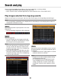
Play images selected from logs (log search)
Display the alarm log list or error log list, and click a date & time to play the corresponding recorded images.
Note:
• The corresponding recorded data that is displayed in the selected log list cannot be played if the data has
already been overwritten or erased.
Step 1
Click the [Alarm] button or [Error] button on the status
display panel.
→ The corresponding [Log] buttons will be displayed.
Step 2
Click the [Log] button.
→ The alarm log panel or error log panel will be displayed. It is possible to switch between list pages
by clicking the [Previous]/[Next] buttons.
Note:
• Up to 750 alarm logs are saved. When more than
750 logs are filed, the older logs will be overwritten by the newer logs. In this case, the oldest log
is the first to be overwritten.
• Up to 1000 error logs are saved. When more than
1000 logs are filed, the older logs will be overwritten by the newer logs. In this case, the oldest log
is the first to be overwritten.
Step 3
Select the line with the desired date & time, and click
the playback button on the playback operation panel.
(☞ Page 26)
→ Playback will start from a point approx. 5 seconds
before the date & time selected.
Note:
• Playback can also be started by double-clicking
the desired date & time line.
• To start playback from the beginning of the preevent recording when the "Pre-event duration"
setting is longer than 5 seconds, click the playback button, and then click the previous record
button.
32
Step 4
Note:
• Playback can also be stopped and live images
can also be displayed by the following operations:
• Clicking the [x] button on the date & time operation panel (playback display)
• Changing the playback medium
To stop playback and return to live images, click the
stop button on the playback operation panel.
(☞ Page 26)
→ Playback will stop, and live images will be displayed.
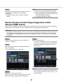
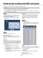
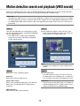
Search and play recorded images triggered by motion
detection (VMD search)
Search images recorded with a camera supporting the VMD search function by the date motion was detected
and play them. Click a date & time on the result list to play corresponding recorded images.
Important:
• To perform the motion detection search, it is necessary to configure the settings of the connected cameras
that support the motion detection search function in advance. Refer to the "readme.txt" on the provided
CD-ROM about the supported camera. Refer to the operating instructions of the camera in use for further
information.
Step 1
Step 4
Display the images from the camera to search on a
1-screen. (☞ Page 20)
Click the [Search] button.
→ This will run a VMD search within the designated
search range and display a list of results. Switch
between list pages by clicking the [Previous]/
[Next] buttons.
Step 2
Click the [Search] button on the playback operation
panel. (☞ Page 26)
→ The VMD search panel is displayed.
Note:
• Up to 100 logs are saved in the list. When more
than 100 logs are filed in the search result, "> 100"
will be indicated.
Step 3
Designate the time range to search.
Set the year, month, day and time of the start and end
point by clicking the respective [D] / [C] buttons.
33
• The VMD search function searches the entire
camera image by default. To designate a search
area, click the [Setup] button next to [Detection
area / Mask duration] on the "VMD search setup"
panel. (☞ Page 34)
• It may take some time until the search results are
displayed.
Step 6
To stop playback and return to live images, click the
stop button on the playback operation panel.
→ Playback will stop, and live images will be displayed.
Note:
• Playback can also be stopped and live images
can also be displayed by the following operations:
• Clicking the [x] button on the date & time operation panel (playback display)
• Changing the playback medium
Step 5
Select the line with the desired list, and click the playback button on the playback operation panel.
(☞ Page 26)
→ Playback will start from the date & time selected.
Note:
• Playback can also be started by double-clicking
the desired date & time line.
Set up VMD areas, etc. [VMD search setup]
Set up VMD areas within images and a mask duration.
Step 1
Step 3
Display the images from the camera to search on a
1-screen. (☞ Page 20)
On the displayed image, click the upper left and lower
right corner of the square that will become the VMD
area.
→ The area set up for VMD search turns gray.
Step 2
Click the [Setup] button next to [Detection area /
Mask duration].
→ The "VMD search setup" panel will be displayed.
Note:
• As the detection areas will be set up to match the
image display area divided into 16x16 segments,
the top left and bottom right detection areas may
not be exactly as designated.
• It is impossible to delete the detection area that
has been set. To change the detection area setting, perform Step 3 again.
34
Step 4
Step 5
If VMD search takes too much time or the search produces too many results, set a mask duration to
reduce the search frequency. When mask duration is
set, no motion detection will be performed from the
time motion is detected to the time mask duration is
set.
To set, click the [C] button next to [Mask duration
setup] on the advances setup panel.
Mask duration: 1 s/ 5 s/ 10 s/ 30 s/ 1 min/ 5 min/
10min
Default: 1 s
Click the [Back] button or the [x] button.
→ The display returns to the VMD search panel.
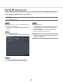
About captured images
When the captured image button (☞ page 27) is clicked to display data saved on SD memory card on a PC, the
data format and destination to save are as follows:
File format for recorded images: JPEG (DPOF-compatible)
Destination to save: SD memory card
[DCIM]\100_PANA\P1000001.JPG
P1000002.JPG, ...
* The folder will be created from 100_PANA to 999_PANA. If the folder already contains the file P1000999.
JPG, a folder with a new number will be created.
35
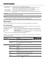
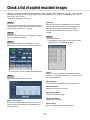
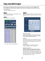
Play back copied images
Display a list of recorded images copied onto an SD memory card or a DVD disc* (copied data), select recorded
images from the list, and play them. It is possible to search for copied data using filters.
* DVD-drive-equipped models only (No audio will be heard when a DVD disc is being played back.)
Note:
• It is also possible to set the start point and end
point of the filter range by clicking the [Start]/[End]
buttons after selecting the desired time in the
[Playback] box and clicking the desired date on
the calendar.
Step 1
Insert an SD memory card or a DVD disc on which
the recorded data are copied. (☞ Page 9)
Step 2
Click the [SD] button or [DVD] button on the playback
operation panel to select the playback media.
→ The media playback panel will be displayed.
Up to 10000 logs are saved in the list. When more
than 10000 logs are filed in the search result,
"> 10000" will be indicated.
Step 4
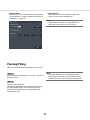
Click the [Filtering] button.
→ A list of search results for the specified filter criteria is displayed. Switch between list pages by
clicking the [Previous]/[Next] buttons.
Step 5
Select the line with the desired list, and click the playback button on the playback operation panel.
→ Playback will start from the date & time selected.
If the multiscreen was displayed, it will change to
the 1-screen.
Note:
• Playback can also be started by double-clicking
the desired date & time line.
• If the selected copied data is password protected,
the password entry screen will be displayed. Enter
the assigned password, and click the [OK] button.
If the wrong password is entered, the copied data
cannot be played back. For character entry, refer
to "About the operation of on-screen keyboard"
(☞ page 16).
Step 6
To stop playback and return to live images, click the
stop button on the playback operation panel.
→ Playback will stop, and live images will be displayed.
Step 3
To filter the number of items displayed on the copied
data list, proceed as described below.
To play back without filtering, proceed to Step 5.
Note:
Playback can also be stopped and live images
can also be displayed by the following operations:
• Clicking the [x] button on the media playback
panel.
• Changing the playback medium
Filtering by camera
Mark the checkbox for [Filtering by camera]. Filtering
will be applied to the camera whose image is displayed.
Filter by designating date & time
Specify the filter range by designating a date & time.
To specify the filter range, set the year, month, day
and time of the start and end point by clicking the
respective [D]/[C] buttons.
36
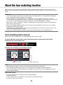
Event function
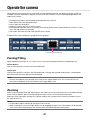
The recorder will take an event action when any of the following events occur.
• Terminal alarm:
An event when an alarm input signal is supplied from an external device such as a
door sensor to the alarm input terminal on the rear of the recorder.
• Camera site alarm:
An event when an alarm (camera terminal alarm, etc.) is detected by a camera.
• Command alarm:
An alarm when receiving an alarm from a PC, etc. via a network.
• Face matching alarm: Alarm issued when a face contained in a live image matches an already registered
facial image.
Important:
• Face matching alarm does not apply event recording.
Note:
• For setting conditions and limitations applicable to the face matching alarm, refer to the Installation Guide.
Face matching alarm is available when this function has been configured for use.
Event action
When the recorder recognizes an event, it will take an event action according to the set action mode.
Event action mode
In the event modes shown below, the recorder takes one of the following event actions when an event occurs.
The event action mode can be configured on the setup menu.
Recording & alarm action:
Performs all event actions according to the settings. ("A" in the following table)
Recording only:Performs only recording, filing alarm logs, and moving to camera presets. ("B" in
the following table)
Alarm action:
Performs only alarm actions according to the settings. ("C" in the following table)
Off:
Files only alarm logs. ("D" in the following table)
* "Alarm action" can be selected only for the face matching alarm.
A different event action will be taken depending on the selected event action mode. Refer to a system administrator for further information.
Event action
Recording
Alarm action
Description
Start event recording
Recording will start according to the recording
duration configured on the setup menu.
Define pre-event
recording
Camera images recorded before an event occurs
can be associated with the event and saved on
the hard disk.
Mode*1
A
B
●
b
C
×
D
×
●
●
×
×
Move the camera to Move the camera to the preset position registered
the preset position in advance.
●
●
×
×
Blink the alarm indi- The alarm indicator on the front panel will start
cator
blinking.
b
×
b
×
Sound the buzzer
The buzzer will start sounding for the duration set
in advance.
●
×
●
×
Send alarm output
signals
Output signals will be sent from the ALARM/
CONTROL connector at the rear of the recorder.
●
×
●
×
Display event information on the main
monitor
The event type and terminal/camera number will
be displayed on the status display panel. At the
same time, the alarm button turn red.
b
×
b
×
37
Event action
Alarm action
Mode*1
A
B
The alarm icon will be displayed on the event error b
b
display area of the web browser.
Description
Display the alarm
icon on a web
browser
C
b
D
×
Display the alarm
message on a web
browser
A window that notifies of an event occurrence will
be displayed on the web browser.
* The alarm message displayed last has priority.
To close the window, click the [x] button.
●
×
●
×
Record the alarm
logs
Date & time of the event and event information will
be recorded in a log list.
b
b
b
b*2
Send a mail that
notifies of an event
occurrence
An e-mail notifying of the event and its date & time
(alarm mail) will be sent to registered e-mail
addresses (up to 4).
●
×
●
×
Provide an alarm
notification to a PC
according to the
Panasonic alarm
protocol setting
When an event occurs, a notification will be sent
to a PC in accordance with the settings made
under [Panasonic alarm protocol]. (☞ Installation
Guide)
●
×
●
×
●
×
●
×
Display the images Display the images recorded by the camera assoon a 1-screen when ciated with the alarm number on a 1-screen
an alarm occurs
*1 b: Takes action regardless of the setting, ●: takes action in accordance with the setting, ×: takes no action
*2 Since the face matching function is not performed when "Mode" - "Advanced face matching alarm set up"
is set to "Off", there is no entry made into the log either.
Stop buzzer beeping
The buzzer sounding to announce an alarm or error can be stopped from the recorder’s front panel.
Step 1
Press the [BUZZER STOP] button.
→ The buzzer will stop.
Note:
• The buzzer can also be stopped by canceling the
alarm action or error action. (☞ Page 39) The
[BUZZER STOP] button does not reset any of the
other alarm actions.
38
Cancel the alarm action
The recorder will take an alarm action according to the settings configured in advance when an event occurs in
the alarm mode (ALM). Information of the occurred alarm will be displayed on the status display panel of the
main monitor. (☞ Page 14)
To reset the alarm action, click the [Alarm] button on the status display panel, and click the alarm [Reset] button.
When an item other than "Ext." is selected for "Auto reset time" on the "Event setup" tab under "REC & event"
on the setup menu (☞ Installation Guide), the following actions will automatically be taken, unless the alarm
action is canceled by clicking the alarm [Reset] button.
• The alarm indicator on the front panel will stop blinking and light steadily.
• The alarm status display on the main monitor will disappear.
• The sounding buzzer and the alarm output will stop.
Step 1
Click the [Alarm] button displayed on the main monitor, and click the alarm [Reset] button.
→ The alarm action will be canceled and the alarm
indicator will go off.
Note:
• When the alarm action is canceled, the event
recording will stop and return to the operational
status just before the event occurred.
Cancel the error action
When an error (trouble) occurred on the recorder, the recorder will take the error action (a series of actions that
notifies of the error occurrence). Information of the occurred error will be displayed on the status display panel
of the main monitor. (☞ Page 14)
To cancel an error action, first click the [Error] button on the status display panel and then the displayed error
[Reset] button.
Note:
• When an error occurs, take remedial action by following the instructions displayed on the error log panel (☞
page 32). The error lamp on the front of the recorder will go off when the cause of the error has been eliminated.
39
Copy recorded images
It is possible to manually copy images recorded in the recorder onto an SD memory card and DVD (DVD-R, +R)
disc.
It is recommended to make back-up copies on a regular basis for unexpected situations such as malfunction of
the hard disk drives.
It is impossible to copy recorded images when the recorder is in the following statuses.
• When the copy window is being opened by other user via a network
• When the SD memory card or DVD disc is being selected by another user via a network
• When the media other than hard disk drives is selected
The copied recorded images can be played on the recorder or on a PC using the dedicated viewer software.
The viewer software will be automatically copied to an SD memory card or a DVD disc on which recorded images are copied.
Refer to page 87 for how to operate the viewer software. Refer to page 36 for how to play the copied recorded
images on the recorder.
Note:
• Recording on a DVD disc is available only with DVD-drive-equipped models.
• Pause the playback before starting copying when playing recorded images on the recorder.
• To copy recorded images onto an SD memory card, it is necessary to format an unformatted SDHC/SD
memory card or an SDHC/SD memory card formatted with another device on this recorder. (☞ Page 44)
• Required time for copying varies depending on the data size to be copied. It will take longer time to copy
recorded images when they were recorded with a larger image capture size, in a higher quality or at a higher
frame rate even though the same number of cameras and the same duration are set for copying.
• Copying of recorded images may sometimes be performed incorrectly when there exist 2 or more images
recorded at the same date & time resulting in change of the date & time setting or the auto time adjustment
function.
• In the following cases, the copying currently being performed will stop.
• When any of the settings of the recorder is changed
• When a user who started manual copy logged out or when auto logout is activated (It will take around 90
seconds until copying is stopped after the web browser is closed.)
• When the original data (source for copying) is lost (overwritten or malfunction of the hard disk drive)
Important:
• If data is once copied on a DVD disc, no more copy will be possible after ejection. Step 1
Insert an SD memory card or a DVD disc into the
recorder. (☞ Page 9)
Step 2
Click the [Copy] button on the operation panel of the
main monitor.
→ The copy panel will be displayed (if in playback
mode, playback will be paused).
40
Note:
• The copy panel cannot be displayed in the web
browser when it has already been opened by
another user. When copying is already underway,
the copy cancel window will be displayed.
Note:
• To attach a code for alteration detection, click the
[Advanced] button. On the advanced setup window, set [Attach the alteration detection code] to
"On".
Step 3
The following items can be set up for copying of
recorded data:
Item
Description
Camera selection
Check the number of the camera whose recorded data is to
be copied. Checking [Check all]
will copy the recorded data of
all cameras.
Copy drive
Indicates the copy destination.
* "DVD" will be displayed only
for DVD-drive-equipped models.
Date & Time range
Specify times and dates to
define the range for copying
recorded data. Set the year,
month, date & time of the start
point and end point.
It is also possible to set the
start point and end point of the
filter range by clicking the
[Start]/[End] buttons after clicking the desired date on the calendar and then selecting the
desired time in the [Playback]
box.
• Clicking the [Back] button will return to the copy
panel.
Step 4
Click the [Copy] button on the copy panel.
→ If the [Assign a password] checkbox has been
marked, the password entry screen will be displayed.
Otherwise proceed to Step 6.
Assign a password Check this item to assign a
password to the copied data.
The password will be required
to play back copied data that is
password protected.
Free
The remaining space of the
storage medium will be displayed.
Data size
The total volume of all recorded
images to be copied (including
the viewer software) will be displayed.
* Indicated as *.** GB while the
data volume is being calculated.
41
Step 5
Step 7
Enter the password, and then click the [Next] button.
For character entry, refer to "About the operation of
on-screen keyboard" (☞ page 16).
• Enter 5 to 8 alphanumeric characters for a password.
• To confirm the password, enter the same password again into the "Confirm" column.
• To save the entered password, check "Memorize
password temporarily". The next time data is copied, the password entry window will open with the
password already filled in. The password will be
retained in memory until the power of the recorder
is turned off
When copying on a DVD disc, a confirmation window
is displayed on completion.
To continue copying, select "Not eject a medium" and
click the [OK] button.
→ The copy start confirmation window will be displayed.
Step 8
After all the required data is copied to the disc, select
"Eject a medium" on the confirmation window and
click the [OK] button.
→ The finalization confirmation window will be displayed. When the [OK] button is clicked, finalization (the proce-dure to eject the DVD) will be performed. After the procedure is complete, the disc
can be ejected. Press the eject button.
Step 6
Click the [OK] button in the copy start confirmation
window.
→ "Copying" is displayed in the status display area,
and copying will start. When copying is completed, "Copying" will go off.
Important:
• Do not remove the SD memory card during copying data onto the SD memory card. Otherwise the
data stored on the SD memory card could be lost.
• If the copy destination lacks sufficient remaining
storage capacity, copying will continue until the
medium is full. Use a medium with sufficient storage capacity to avoid left over data that is not
copied.
• Copying will be performed in the following order:
Viewer Software → Images → Audio Depending
on the designated time range for copying and the
remaining space of the storage medium, images
and audio may not be copied.
• Clicking the [Copy] button during the copying process will display the copy cancel confirmation
window, allowing you to cancel copying. Copying
continues while the copy cancel confirmation window is displayed.
• Do not turn off the power of the recorder while
copy is in progress. If the power is turned off while
copying, the storage media copied on will become
unusable.
• It is possible to copy up to 10000 data on an SD
memory card and up to 25000 data on a DVD
disc. However, it is impossible to copy any more
data exceeding these limits even when there is a
sufficient remaining capacity.
Important:
• If the disc is not finalized, the tray may not open
even after the eject button is pressed.
• If data is once copied on a DVD disc, no more
copy will be possible after ejection.
• When "Failed to finalize." Is displayed, the disc
can be ejected, but cannot be played back. In this
case, retry coping on another disc.
The disc can be ejected as follows instead of step 8.
42
Click the [Copy] button
Clicking the [Copy] button on the operation panel of
the main monitor after copying is complete will display the following window:
Select "Eject a medium" and click the [OK] button to
perform finalization (the procedure to eject the DVD
disc). When finalization is complete, the completion
window will be displayed, indicating that the DVD
disc can be removed. Then, press the eject button.
Finalize the copy from the copy window
After copying is complete, first click the [Advanced
setup] button on the copy panel and then the
[Execute] button next to "DVD finalize" in the
advanced setup window.
→ When the confirmation window is displayed, click
the [OK] button to perform finalization (the procedure to eject the DVD disc). When finalization is
complete, the completion window will be displayed, indicating that the DVD disc can be
removed. Then, press the eject button.
43
Format SD memory card
To copy recorded images onto an SD memory card, it is necessary to format an unformatted SDHC/SD memory
card or an SDHC/SD memory card formatted with a PC or another device with this recorder. Note that formatting the SD memory card will delete all data stored on it.
Important:
• Formatting will delete all data and setup information stored on an SD memory card. Image data once deleted cannot be restored.
Step 1
Step 4
Click the [Copy] button on the operation panel of the
main monitor. (☞ Page 40)
→ The copy start confirmation window will be displayed.
Click the [OK] button.
→ Formatting of the SD memory card will start, and a
window indicating that formatting is in progress
will be displayed.
When formatting is completed, the format completion window will be displayed.
Step 2
Click the [Advanced] button.
→ The "Advanced setup" window will be displayed.
Important:
• Do not turn off the power of the recorder while formatting is in progress.
Step 3
Click the [Execute] button for "SD card format".
→ The confirmation window will be displayed.
44
About the face matching function
When the face matching function is activated, it detects facial features of people in images, matches them
against similar facial features recorded earlier or contained in live images, and issues an alarm when a match is
found.
Important:
• Facematchingdoesnotworkwhilerecordedimagesarebeingplayedorthesetupwindowisdisplayed.
• Facematchingalarmdoesnotapplyeventrecording.
• Whenusingthefacematchingfunctionontheoperationscreen,thedisplaychangesto1-screenor
4-screen display, on the wide view screen, it changes to 3-screen display. It will not work on the multiscreen
(1-screen or 4-screen display when the screen segments are equally divided by the setting).
• When"Alarmaction"isselectedfor"Mode"of"Advancedfacematchingalarmsetup",thesequentialdisplay on the live monitor stops.
• Whenseveralpeopleappearinimagesatthesametime,facematchingmaytaketime,oritmaynotbe
possible to match all facial images.
• Adetectedpersondisplayedonthefacematchingresultwindowmaysometimesnotbethesameasthe
one who has registered the facial image.
• Refertotheinstallationguideforsetupandfurtherinformationaboutthefacematchingfunction.
Face matching alarm actions
When a face matching alarm occurs, the following notifications will be issued:
An alarm indication and the name of the facial image (name of detected person) will be
displayed in the status display area.
The latest face matching result will be displayed
Matched facial image
Registered facial image
Note:
• Whendisplayingimagesinwideview,theoperationpanelwillopenautomatically.
• Whencopyingorplayingbackimages,thefacematchingresultwindowwillnotbedisplayed.
• Upto16facialimagescanbememorized.Itispossibletoswitchbetweenfacialimagesbyclickingthe
[Previous]/[Next] buttons.
Other alarm actions
• Thealarmindicatoronthefrontpaneloftherecorderwillblink.
• Thebuzzersounds.
• Afacematchingalarmisoutputfromaterminalontherearpanel(ifsetup).
• Analarme-mailissent(ifsetup).
45
Reset face matching alarm
Proceed as described below to cancel the face matching alarm.
Note:
• To close the face matching result window, click
the [x] button.
Step 1
Click the [Alarm] button on the status display panel.
→ The alarm [Reset] button will be displayed.
Step 2
Click the alarm [Reset] button.
→ The face matching alarm indication disappears.
Alarm actions (buzzer/terminal output) will be
stopped at the same time.
Display the face matching thumbnail again
Proceed as described below to display the face matching result window again after having closed it once.
Step 1
Click the [Alarm] button on the status display panel.
→ The [Thumbnail] button will be displayed.
Step 2
Click the [Thumbnail] button.
→ Click this button to display the face matching
result window.
Note:
• The face matching result window display the latest matching facial images found. The face
matching results are updated even while the fact
matching result window is opened.
46
Start/stop face matching actions manually
The face matching actions can be changed manually.
Step 1
Click the [Alarm] button on the status display panel.
→ When face matching is stopped, the [Face:On]
button is displayed, when it is in progress, the
[Face:Off] button appears.
: Face matching in progress
: Face matching stopped
Step 2
Click the [Face :On] button or the [Face :Off] button.
→ This starts or stops face matching.
Note:
• When using the face matching function on the
operation screen, the display changes to 1-screen
or 4-screen display, on the wide view screen, it
changes to 3-screen display. It will not work on
the multiscreen (1-screen or 4-screen display
when the screen segments are equally divided by
the setting). The function will not work on the multiscreen.
• Face matching will stop when playback of recorded images is started during face matching. The
face matching operation is resumed, when playback is stopped.
• When "Alarm action" is selected for "Mode" of
"Advanced face matching alarm setup", the
sequential display on the live monitor stops.
(☞ Installation Guide)
47
Operate the camera
When displaying live images from a camera with the panning/tilting function on a 1-screen or 4-screen, the following camera operations are available.
Note:
• It may be impossible to operate the camera or some functions may be inoperable depending on the model
of the camera.
• Operations are performed from the operation window. When working with the wide view screen, open a
1-screen or 4-screen operation window by clicking the [Ctrl screen] button in the bottom right corner of the
screen.
• For a fixed camera, the buttons on the camera control panel and other controls will be disabled.
Camera control panel
Operate the cameras displayed as selected (inside selection frame) in the image display area. On the 1-screen,
the camera whose image is currently displayed, can be operated. On the 4-screen, click the camera number
panel on the operation panel, or select a camera image by clicking it in the image display area.
Control buttons
[Detail] button
Display the "Camera control [Advanced]" panel, and
perform any of the following camera operations:
Control buttons
Move (pan/tilt) the camera in the clicked direction.
Keeping the button pressed will move the camera
continuously.
• [Focus] button
Adjust the focal point.
[Zoom] button
Adjusts the zoom factor.
• [Brightness] button
Adjusts the lens iris of the camera.
[Home position/Call] button
Move the camera to the home position.
• Auto mode
Activates the auto mode function of the camera.
[Enable camera control with mouse] checkbox
When this item is checked, pan/tilt (clicking) and
zoom (mouse wheel) can be controlled with the
mouse on the selected camera image.
Note:
• When this checkbox is marked, digital zooming
(☞ page 24) by turning the mouse wheel operation
is not possible. When the camera control panel is
inoperable for the fixed camera, the digital zoom
can be performed by turning the mouse wheel
even when the checkbox is checked.
• [Position]
Registers the current orientation of the camera as
a preset position. Moves the camera to a previously registered preset position.
48
• [Setup] button
Displays the camera setup window for registering
a home position (☞ page 53) and executing auto
back focus (☞ page 53).
• [Back] button
Closes the "Camera control [Advanced]" and
returns to the camera control panel.
Note:
• Controlling the cameras is not possible on the
wide view screen and on the 16-screens.
Panning/Tilting
Adjusts the horizontal/vertical position of the camera.
Note:
• To enable operations in the displayed camera
image from the recorder, check "Enable camera
control with mouse" on the camera control panel.
Step 1
When displaying the images on a 4-screen, select the
desired cameras.
Step 2
Click the [Control] button.
Click the desired point to be located at the center of
the angular field of view. The camera will move to
locate the clicked point as the center point in the
image display area.
49
Zooming
Zoom the displayed camera image in/out by zooming the camera lens. Depending on the models of the connected cameras, the available zooming factors may be different. Refer to the operating instructions of the camera for further information.
Note:
• To enable operations in the displayed camera
image from the recorder, check "Enable camera
control with mouse" on the camera control panel.
• When selecting an area in the image display area
by dragging the mouse, the selected area will be
located at the center of the image display area
and the zoom ratio will be adjusted automatically.
Step 1
When displaying the images on a 4-screen, select the
desired cameras.
Step 2
Click the [–] button or the [+] button.
Alternatively, adjust the zoom by placing the mouse
pointer on the image and turning the mouse wheel.
Click the [x1] button to reset zoom.
Move to home position
Move the camera to a previously registered home position. The home position needs to be registered in
advance. (☞ Page 53)
Step 1
When displaying the images on a 4-screen, select the
desired cameras.
Step 2
Click the [Call] button to move to the home position.
Focus adjustment
Adjust the focal point. The auto focus function is available.
Step 1
Step 3
When displaying the images on a 4-screen, select the
desired cameras.
Click the [Near] or [Far] button.
The auto focus function can be performed by clicking
the [Auto] button.
Step 2
Click the [Detail] button.
→ The "Camera control [Advanced]" panel will be
displayed. (☞ Page 48)
50
Iris (brightness) adjustment
Adjusts the lens iris of the camera.
Step 1
Step 3
When displaying the images on a 4-screen, select the
desired cameras.
Click the [–] or [+] button.
It is possible to reset the set brightness by clicking
the [Reset] button.
Step 2
Click the [Detail] button.
→ The "Camera control [Advanced]" panel will be
displayed. (☞ Page 48)
Auto mode
Activates the auto mode function of the camera.
Step 1
Step 4
When displaying the images on a 4-screen, select the
desired cameras.
Click the [Start] button to start the selected auto
mode function.
Click the [Stop] button to turn off the auto mode function of the camera.
Step 2
Click the [Detail] button.
→ The "Camera control [Advanced]" panel will be
displayed. (☞ Page 48)
Note:
• Refer to the operating instructions of the connected camera for further information about the auto
mode function of the camera.
Step 3
Click the auto mode button [C] of the camera, and
select one of the following auto modes:
Auto track: The camera will automatically track an
object moving on the screen.
Auto pan: The camera direction will automatically
move (pan) between the start point and end
point set in advance.
Preset sequence: The camera will move (pan) to
the preset positions registered in advance in
order of the preset position number (numerical
order).
Patrol: The camera will trace the manually recorded panning pattern.
51
Register camera preset positions
Register the current camera position as a preset position. The preset positions can be registered only when
using a camera supporting the preset position function.
Step 1
Step 4
When displaying the images on a 4-screen, select the
desired cameras.
Click the [D]/[C] button in the [Position] box to select
a preset number. Select a preset number (1 - 256) to
be registered.
Step 2
Step 5
Click the [Detail] button.
→ The "Camera control [Advanced]" panel will be
displayed. (☞ Page 48)
Click the [Regist] button.
→ The camera direction will be registered to the
selected preset position number.
Step 3
Perform the pan/tilt operation to move the camera to
the position to be registered. (☞ Page 49)
Move camera preset positions
Move the camera to the registered preset position. It is necessary to register preset positions in advance.
Step 1
Step 4
When displaying the images on a 4-screen, select the
desired cameras.
Click the [Call] button.
→ The camera direction will move to the preset position corresponding to the selected preset position
number.
Step 2
Click the [Detail] button.
→ The "Camera control [Advanced]" panel will be
displayed. (☞ Page 48)
Note:
• A non-registered preset number can be selected,
but the camera will not move even if the [Call] button is clicked.
Step 3
Click the [D]/[C] button in the [Position] box to select
a preset number. Select a preset number (0 - 256) to
be registered. Selecting preset position number 0 will
move the camera to home position.
52
Register home position
The home position is set with the camera positioned at an already registered preset position.
Note:
• On some Panasonic camera models, preset position number 0 is registered as home position.
Refer to the "readme.txt" on the provided
CD-ROM about supported cameras.
Step 1
Register the camera preset positions on the "Camera
control [Advanced]" panel. (☞ Page 48)
Step 2
Click the [Setup] button.
→ The camera setup window will be displayed.
(☞ Page 49)
Step 4
Click the [Regist] button.
→ The selected preset number will be registered as
the home position.
Step 3
Click the [D]/[C] button in the [Position] box to select
a preset number to register as the home position.
Select a preset number (1 - 256) to register.
Step 5
Click the [Back] button.
→ The camera setup window closes, and the display
returns to the "Camera control [Advanced]" panel.
Execute auto back focus
The auto back focus function starts to automatically adjust back focus based on a subject located in the center
of the screen by clicking the execute button. For further information about this function, refer to the operating
instructions of the camera in use.
Step 1
When displaying the images on a 4-screen, select the
desired cameras.
Step 2
Display the "Camera control [Advanced]" panel
(☞ page 48), and click the [Setup] button.
→ The camera setup window (☞ page 49) will be displayed.
Step 3
Click the [Execute] button next to "Auto back focus".
Step 4
Click the [Back] button.
→ The camera setup window closes, and the display
returns to the "Camera control [Advanced]" panel.
53
Set up mask areas
Set up mask areas of the camera. For further information about this function, refer to the operating instructions
of the camera in use.
Step 1
Click the [Start] button.
→ A grid will appear over the image display area and
the segments designated as mask areas are covered with white translucent masks.
Step 2
Click a segment in the image display area.
→ Each click of the segment toggles between On
and Off for the mask area setting.
Step 3
Click the [End] button.
→ The mask area setting will be completed and the
grid will disappear.
Step4
Click the [Back] button.
The camera setup window closes, and the display
returns to the "Camera control [Advanced]" panel.
Note:
• It is possible to reset all the mask area settings by
clicking the [Reset] button.
54
Configure the network settings
The recorder can be operated using a mouse connected to the front of the unit or from a web browser on a PC
(excluding certain functions and settings). On the following pages, operation from a web browser, setting up the
PC and related matters will be described.
When operating the recorder using a web browser, it is necessary in advance to configure the network settings
of the recorder and a PC.
When the network settings of the PC are as follows, it is unnecessary to configure the settings. It is possible to
configure the settings and operate the recorder using a web browser after completing the connection.
IP address: 192.168.0.2 - 192.168.0.249, 192.168.0.251 - 192.168.0.254
Subnet mask: 255.255.255.0
Default gateway: 192.168.0.1
When the settings are configured differently from the above, configure the network settings of the recorder or a
PC.
Configure the network settings of the recorder
The network settings of the recorder can be configured on the "Network" page - the [Basic] tab of the setup
menu.
Refer to the chapter relating to the [Basic] tab of "Network" of the setup menu for how to operate (☞ Installation
Guide).
Configure the network settings of the PC
The TCP/IP setting of the PC shall be changed to conform to the settings of the recorder. When using the
recorder with the default (IP address:192.168.0.250), set the IP address of the PC to "192.168.0.xxx (a number
from 2 to 254 except 250 (this recorder))".
The settings described in these operating instructions are based on the standard settings for Windows 7. Refer
to the operating instructions of the respective OS for further information.
Step 1
Important:
• Log in to the PC as an administrator.
Click "Control Panel" on the start menu.
→ "Control panel" will be displayed.
55
Step 2
Step 4
Click "View network status and tasks".
Click [Properties]
→ The "Network and Sharing Center" window will be
displayed.
Step 3
Click "Local Area Connection".
→ The "Local Area Connection Properties" window
will be displayed.
Step 5
Click "Internet Protocol Version 4 (TCP/IPv4)", and
then [Properties].
→ The "Local Area Connection Status" window will
be displayed.
→ The "Internet Protocol Version 4 (TCP/IPv4)
Properties" window will be displayed.
56
Step 6
Select [Use the following IP address] and set "IP
address" and "Subnet mask" as follows:
• IP address: 192.168.0.9
• Subnet mask: 255.255.255.0
Depending on the network configuration, it is necessary to configure "Default gateway". Refer to a system administrator for further information about the
settings.
Step 7
Click the [OK] button and close the window.
57
Network security of the recorder
The security function of the recorder
q Access restriction by the user authentication
It is possible to restrict users to access the recorder by selecting "On" for "User authentication". (☞
Installation Guide)
w Access restriction by changing the HTTP port number
By changing the HTTP port number, it is possible to prevent illegal access such as a port scanning, etc. (☞
Installation Guide)
Important:
• Design and enhance security countermeasures to prevent leakage of information such as image data,
authentication information (user name and password), alarm mail information, FTP server information, etc.
Perform the countermeasure such as the access restriction using the user.
• After the unit is accessed by the administrator, make sure to close the web browser for added security.
• Change the administrator password periodically for added security.
Enhance network security
It is possible to enhance the network security by dividing the subnet using a router to authenticate users twice
(by the recorder and by the router). When connecting the recorder to an unsecured network, secure the network
connection by installing a VPN (Virtual Private Network) device, etc. between the recorder and the host PC.
Important:
• The settings for the network security vary depending on the network to which the recorder is to be connected such as an intranet or Internet service provider. Refer to a network administrator for further information
about the network security.
[Connection example]
Router
IP address: 192.168.1.1
Subnet mask: 255.255.255.0
Router
IP address: 192.168.0.1
Subnet mask: 255.255.255.0
Network
IP address: 192.168.1.100
Subnet mask: 255.255.255.0
Default gateway: 192.168.1.1
Recorder
IP address: 192.168.0.250
Subnet mask: 255.255.255.0
Default gateway: 192.168.0.1
PC
By using a firewall, etc., it is possible to use packet filtering and protocol filtering to enhance the network security.
58
Firewall
Router
IP address: 192.168.1.1
Subnet mask: 255.255.255.0
Router
Network
IP address: 192.168.0.1
Subnet mask: 255.255.255.0
Switching hub
IP address: 192.168.1.100
Subnet mask: 255.255.255.0
Default gateway: 192.168.1.1
Recorder
IP address: 192.168.0.250
Subnet mask: 255.255.255.0
Default gateway: 192.168.0.1
PC
59
Display the operation window
Boot the PC and operate the recorder using a web browser.
Step 1
Step 3
Start the web browser.
Enter the user name and password registered in the
recorder, and then click the [Login] button.
Step 2
Enter the IP address or URL assigned to the recorder
into the address box, and then press the [Enter] key.
→ The authentication window will be displayed. The
authentication window will not be displayed when
"Off" is selected for "User authentication" on the
[Basic] tab of "User management" of the setup
menu.
Important:
• Refer to a system administrator for further information about the set IP address.
• Do not attach "0" before the numbers when entering IP address.
Example: b 192.168.0.50
× 192.168.0.050
• If a message is displayed on the information bar,
see page 98.
Note:
• When the top page is displayed for the first time,
the install wizard of the ActiveX control required to
display images from the camera will be displayed.
Follow the instructions of the wizard.
• The ActiveX control and the viewer software (☞
page 85) will be installed at the same time.
• Follow the instructions of the wizard to complete
the installation. When any ActiveX control for a
Panasonic recorder other than this product is
already installed, uninstall "WebVideo ActiveX"
from "Uninstall a program" and then install
ActiveX control for this product. (☞ Page 85)
• When the installation wizard is displayed each
time displaying other page even though installation of ActiveX control for this product has been
completed, reboot the PC.
• The ActiveX control used on each PC should be
licensed individually. Refer to your dealer for the
software licensing.
→ The top page will be displayed.
Important:
• Refer to a network administrator for the set user
name and password.
• Refer to the Installation Guide for how to register
users.
• The default administrator name and password are
as follows.
Administrator name: ADMIN
Password: 12345
• To enhance the security, change the administrator
name and password before running the recorder.
Change the password periodically. Refer to the
Installation Guide for how to change the password.
• Refer to page 98 when a message is displayed on
the information bar or when an unnecessary status bar or scroll bar is displayed on the window.
60
About the operation window
Top Page
Status display area
Current time display area
Image display area
Download operation area
[CAM] tab
[HDD] tab
[Control] button
Displays operations such as searching for and copying recorded images, search results and log information. It can also be used to switch camera images
between display of live images on a multiscreen, wide
screen, etc.
Image display area
Playback images and live images will be displayed.
The camera title is displayed at the upper left and the
date & time (the current date & time of the camera's
clock when displaying live images and the date &
time when the images were recorded when playing
recorded images) at the upper right. Clicking the
camera title while displaying images on a multiscreen
will display images from the respective camera on a
1-screen.
At the default, the aspect ratio of each screen segment is 4:3. Refer to the Installation Guide for the setting to change the aspect ratio to 16:9.
[Cam. select] button
Can be used for camera operations such as switching
camera images.
[Setup] button
Can be used to configure the settings of the recorder.
Refer to the Installation Guide for setup items and
their further information. Refer to page 64 for basic
operations.
Download operation area
Downloads the images currently being played and the
viewer software.
tatus display area
S
The current status of the recorder such as playback
status, recording status, etc. will be displayed.
[CAM] tab
Camera operations such as zooming, focusing, auto
mode, etc. can be performed on this tab.
Current time display area
The current date & time will be displayed.
[HDD] tab
Can be used to play back or operate recorded images.
61
Control panel
The following operation panels will be displayed when the [Control] button is clicked.
List display
area
[Multiscreen] box
Images recorded using up to 4 cameras can be
played simultaneously on a multi-screen. Each click
of the button switches to the next 4 screens in the
sequence: camera 1 to 4→camera 5 to 8→camera 9
to 12→camera 13 to 16.
[Copy data] button
Select [SD] or [DVD] for "Disk/Medium" to display this
button. The copy data search window will be displayed.
Disk/Medium
Select a destination folder to store the current playing
images. ("DVD" will be displayed only for DVD-driveequipped models.)
HDD/ SD/ DVD
[Wide view] box
Displays live or recorded images on a full-screen.
(☞ Page 68)
[Digital zoom] box
Camera image displayed on a 1-screen will be displayed in the proportion of the clicked zoom ratio button.
[x1]: x1, [x2]: x2, [x4]: x4
[Copy] box
Select [HDD] for "Disk/Medium" to display this button. The copy data window will be displayed by clicking this button. Use this button to manually copy
recorded images onto an SD memory card or a DVD
disc.
[Search] box
Use this button to search recorded images. The
search result will be displayed in the list display area.
[Log] box
Select a log for display.
Clicking the buttons will display the respective logs in
the list display area.
Displayed logs: Alarm log, error log, access log,
and network log
[REC event] button
Select [HDD] for "Disk/Medium" to display this button. The recording event search window will be displayed.
[VMD] button
Select [HDD] for "Disk/Medium" to display this button. The motion detection search window will be displayed.
[Close] button
Close the window displaying log information.
62
List display area
Number of data: Displays the total number of listed data.
No: The number will be displayed in the order of
occurrence.
Date & List: Date & time when an event or trouble
occurred will be displayed.
Log: Details of the occurred event are displayed.
Clicking date & time in the list can start playback from
that date & time. (When clicking date & time in the log
information, playback will be started from a point
approx. 5 seconds before the date & time selected.)
To display search results or a list of copied data, refer
to "Search and play recording events" (☞ page 73)
and "Check a list of copied recorded images"
(☞ page 77), respectively.
The following are the maximum number of logs that
can be saved. When the number of logs exceeds the
limit, the older logs will be overwritten by the newer
logs. In this case, the oldest log is the first to be overwritten.
Alarm logs: Up to 750
Error logs:
Up to 1000
Access logs: Up to 100
Network log Up to 100
Note:
• To start playback from the beginning of the preevent recording when the "Pre-event duration"
setting is longer than 5 seconds, click the playback button, and then click the previous record
button.
• The corresponding recorded data that is displayed
in the selected log list or log information cannot
be played if the data has already been overwritten
or erased.
Camera selection panel
Clicking the [Cam. select] button will display the operation panel shown below. Switch the image display area
and select camera images.
Camera selection box
For the [Multiscreen] box, [Wide view] box and [Digital zoom] box, refer to "Control Panel" (☞ page 62).
Camera selection box
Clicking the camera title will display images from the
selected camera on a 1-screen in the image display
area.
63
Setup panel
The following setup panel will be displayed when the [Setup] button is clicked. The settings such as the date &
time display of the recorder can be configured.
[Date/Language] button
Displays the "Date/Language" page. Perform settings
such as time & date and daylight saving time.
[Camera] button
Displays the "Camera" page.
Perform registration of network cameras.
[REC & event] button
Displays the "REC & event" page. Configure the settings relating to the recording schedules and alarms.
[Monitor] button
Configure the settings relating to the main monitor
and the live monitor.
[Network] button
Configure the settings relating to the network.
[User management] button
Register, edit or delete the user information.
The administrator information can also be changed.
[Maintenance] button
Displays the system information of the recorder.
[HDD management] button
Hard disk drives can be formatted.
[Extra function] button
Download the statistics data of the additional business intelligence functions.
(This button will be displayed after registering the
license for the recorder or starting using the recorder
on trial.)
64
Status display area
q
w
e
r
t
w Recording indicator
Indicates the status of recording.
q Live/playback status display area
The status of an image (live image/recorded
image) will be displayed. The following information
will be displayed:
: Indicates that live images are being displayed.
: Indicates that playback images are being
displayed.
: Indicates that reverse playback images are
being displayed.
: Indicates that fast playback images are
being displayed.
: Indicates that fast reverse playback images
are being displayed.
: Indicates that a paused image is being displayed.
: Indicates that recorded images/audio are
being downloaded.
: Indicates that downloading of recorded
images/audio is completed.
: Indicates that recording is being performed.
: Indicates that recording is not being performed.
e Other status display area
Indicates the following statuses.
: Indicates that the camera is inoperable
since a user with a higher priority is currently
operating the camera.
: Indicates that copying is being performed.
: Indicates that recorded images are being
deleted. (Auto deletion only)
: Indicates that face matching is being performed (only if the face matching function
has been set up).
: Indicates that the statistical processing is
being performed.
r Alarm button [ALM]
This button will be displayed when an event
occurs. The alarm action will be canceled by clicking this button.
[Step 1] - [Step 7]: Indicates the playback speed.
: Normal playback speed (1x)
: Approx. 4x playback speed
: Approx. 8x playback speed
: Approx. 16x playback speed
: Approx. 32x playback speed
: Approx. 48x playback speed
: Approx. 96x playback speed
t Error button [ERR]
Indicates that an error has occurred. The alarm
action will be canceled by clicking this button.
: Indicates that the HDD is selected as
playback media.
: Indicates that the SD memory card is
selected as playback media.
: Indicates that the DVD disc is selected
as playback media. (* DVD-driveequipped models only)
: The DVD disc is being finalized.
: Indicates that the formatting of SD memory card or HDD is in progress.
: Indicates filtering of recording events.
65
Download operation area
[Start]/[End] setup
[Start]/[End] setup
Specify the time range for downloading images
and audio by setting a start and end time. This
operation is available only during playback on a
1-screen. (☞ Page 83)
[Viewer] button
Download the viewer software for playing the
downloaded images and audio.
[Download] button
Downloads recorded images and audio at the
designated date & time.
[CAM] tab
When displaying live images from a camera with the panning/tilting function, the following camera controls are
available. Depending on the model of the camera, some operations may not work.
Control buttons/Control pad
[Zoom] box
Zooming can be adjusted by clicking the [–] button
(wide) or the [+] button (tele). Click the [x1] button to
reset zoom.
Control buttons/Control pad
Clicking the buttons around the control pad can move
(pan/tilt) a camera in the clicked direction. Clicking
inside the control pad also can adjust the vertical/horizontal position (pan/tilt) of the displayed images.
Panning/ tilting speed will be faster if a clicked point
gets farther from the center point of the control pad.
[Focus] box
Focusing can be adjusted by clicking the [Near] button or the [Far] button. The auto focus function can
be performed by clicking the [Auto] button.
[Brightness] box
The brightness (lens iris) can be adjusted by clicking
the [–] (darker) button or the [+] (brighter) button. It is
possible to reset the adjusted brightness by clicking
the [Reset] button.
[Auto mode] box
Activates the auto mode function of the camera.
Select the auto mode function (Auto track, Auto pan,
Preset sequence, or Patrol) of the camera by clicking
the [C] button, and then click the [Start] button. Click
the [Stop] button to stop the auto mode function.
66
[Preset Position] box
• [Regist] button
Registers the current camera position as a preset
position.
Select a preset position number (1 - 256) by clicking the [C] button after moving the camera to a
position to be registered as a preset position, and
then click the [Regist] button. It is impossible to
register the position as "Home".
[Call] button
Moves the camera to the preset position registered in
advance.
Select a preset position number (Home, 1 - 256) by
clicking the [C] button, and then click the [Call] button. It is necessary to register preset positions in
advance to move the camera to the preset positions.
[HDD] tab
[Pause] button
Playback will be paused when this button is clicked
during playback. Playback will resume when this button is clicked during pause.
[Play]/[Rev play] button
Plays recorded images in forward or reverse.
[FF]/[FR] button
Plays recorded images at high speed in forward or
reverse.
Playback speed of fast playback will change in the
following order each time this button is clicked:
Step2 (Approx. 4x) → Step3 (Approx. 8x) →
Step4 (Approx. 16x) → Step5 (Approx. 32x) →
Step6 (Approx. 48x) → Step7 (Approx. 96x)
[Stop] button
Stops playback and displays live images.
[Go to last] button
Plays the latest recorded images of the camera currently being displayed. The starting point of playback
is around 30 seconds before the date & time of the
latest recorded images.
[Next record]/[Prev record] button
Skips to the next recorded image or previous recorded image and plays it.
[Date search] box
Start playback by designating the desired date & time
of a recorded image. Click the [C] button and determine the desired date & time.
Clicking the [Date search] button will play back the
images corresponding to the selected date.
[Next image]/[Prev image] button
Clicking this button during playback/pausing will display the next or previous frame and playback will be
paused.
67
Monitor live images from cameras
Live images will be displayed in the web browser window. It is possible to display live images on a 1-screen or
a 4-screen (multiscreen) and to expand the image display area across the full screen.
Display images on a 1-screen
To display live images on a 1-screen, take the following procedures.
Step 2
Step 1
Select the title of the camera.
→ Live images from the selected camera will be displayed.
Click the [Cam. select] button. (☞ Page 61)
→ A list of the registered cameras will be displayed
in the [Camera selection] box.
Note:
• Selecting a camera from the right-click pop-up
menu also will display images from the selected
camera.
• Clicking the [Go to last] button on the [HDD] tab
while displaying live images will start playback
from a point around 30 seconds before the latest
recorded image of the camera currently being displayed.
Use digital zoom
Enlarges the displayed live images.
When playing recorded images on a 1-screen, click a button in the [Digital zoom] box.
[x1] button: Displays live images with x1 zoomed size.
[x2] button: Displays live images with x2 zoomed size.
[x4] button: Displays live images with x4 zoomed size.
Clicking a point in the zoomed image moves the zoomed image by positioning the clicked point as the center
point.
Display images in wide view
Display live images across the full screen. When working on a 1-screen, click the [Wide view] button (the operation panel will disappear).
To return the wide view image to the original size, right-click on the image and select "Ctrl screen" from the displayed menu.
Note:
• To enlarge the displayed live images, also right-click on the live images and select "Wide view" from the displayed menu.
68
Display images on a 4-screen (multiscreen)
Live images from cameras will be displayed on a 4-screen.
Step 1
Click the [Cam. select] button. (☞ Page 61)
→ A list of the registered cameras will be displayed
in the [Camera selection] box.
Step 2
Click the [Multiscreen] button.
→ Live images from the cameras (registered as a
group) will be displayed on a 4-screen.
Step 3
Each click of the [Multiscreen] button switches to the
next 4 screens in the sequence: camera 1 to 4→camera 5 to 8→camera 9 to 12→camera 13 to 16...
Step 4
Click a camera title in the [Camera selection] box or
the camera title displayed on the image to display on
a 1- screen again.
→ The display returns to the 1-screen.
Note:
• To change the screen pattern to a multi-screen,
right-click on the live images and select the item
from the displayed menu.
• Selecting "Wide view" from the right-click menu
will enlarge the displayed images on a 4-screen.
• Clicking the [Go to last] button on the [HDD] tab
while displaying live images will start playback
from a point around 30 seconds before the latest
recorded image of the camera currently being displayed.
• When playing recorded images on a 4-screen, the
audio of the camera assigned to the top left
screen segment will be output.
• When starting VMD search while displaying images on a multiscreen, the camera image displayed
in the top left screen segment will be searched.
69
Play recorded images
Display camera images recorded on the recorder’s hard disk. There are 2 ways to play recorded images as follows.
• Play image recorded at a designated date & time
• Search and play recorded images
Playback operation can be made while recording.
Step 1
Note:
• When displaying images on a 1-screen, audio
assigned to the camera from which images are
currently being displayed will be heard. When displaying images on a multiscreen, audio assigned
to the camera from which images are displayed
on the upper left corner will be heard.
• When starting playback for the first time after
login, playback will start from a point around 30
seconds before the latest recorded image.
• When both a web browser and the viewer software are active, playback of audio may not be
performed correctly. To play audio correctly, use
either the web browser or the viewer software and
close the other.
• When load to be processed is too heavy for the
recorder (such as when many cameras are connected, images (live/playback) are displayed on
many windows (segments)), playback speed may
become slow or playback may stop for a while.
• When displaying images on a multiscreen, playback will be performed while skipping the actual
recording.
• When playing images recorded at a higher frame
rate and images recorded at a lower frame rate
together on a multiscreen, there will be a widening
gap between the displayed times.
• Playback of images and audio may sometimes not
be synchronized.
• The camera image can be changed by clicking the
[Cam. select] button and the camera title during
playback.
• It is possible to switch 1-screen to a multi-screen
during playback by clicking the [Multiscreen] button.
• When clicking a camera title on the image displayed on a multiscreen, images from the camera
whose camera title is clicked will be displayed on
a 1-screen.
Click the [HDD] tab on the top page of the operation
window.
→ The [HDD] tab will be displayed.
Step 2
Click the [Play] button.
→ Playback of a recorded image will be performed.
The "Playback" indication and the "Step 1" indication will be displayed on the status display area.
Playback will start from the point at which the last
playback was stopped (date & time).
Step 3
Click the [Stop] button on the [HDD] tab.
→ "Playback" and "Step 1" will disappear from the
status display area, and playback will stop. Live
images from the camera will be displayed on the
image display area.
70
About playback operation
The following operations are available during playback:
Function
[Play]/[Rev play] button
Example
/
[Stop] button
[Pause] button
[FF]/[FR] button
/
[Next record]/
[Prev record] button
/
[Next image]/
[Prev image] button
/
[Go to last] button
Operation
• Plays recorded images.
• Plays back recorded images in reverse.
* Playback and reverse playback may not work when the [Play]
or [Rev play] button is clicked while recording images at a
lower frame rate.
• Playback will stop and live images will be displayed when this
button is clicked during playback.
• Playback will be paused when this button is clicked during
playback.
• Playback will resume when this button is clicked during pause.
• Playback speed of fast playback will be changed in the following order each time the [FF] button is clicked:
Step2 (Approx. x4) → Step3 (Approx. x8) →
Step4 (Approx. x16) → Step5 (Approx. x32) →
Step6 (Approx. x48) → Step7 (Approx. x96)
• Playback speed of fast reverse playback will be changed in the
following order each time the [FR] button is clicked:
Step2 (Approx. x4) → Step3 (Approx. x8) →
Step4 (Approx. x16) → Step5 (Approx. x32) →
Step6 (Approx. x48) → Step7 (Approx. x96)
• The playback speed will be displayed on the playback status
display.
• When playing H.264/MPEG-4 images, some frames of recorded images will not be displayed. Fast playback/fast reverse
playback of images will be performed with the refresh interval
setting of the camera.
• When the [Next record] button is clicked, playback point will
skip to the start time of the next recorded images.
• When the [Prev record] button is clicked, playback point will
skip to the start time of the previous recorded images.
• When there is no next/previous recorded image to be skipped
to, the current playback will continue. In this case, playback
time of the current playback may sometimes be displayed as
around for 1 minute ago.
• The next frame will be displayed when the [Next image] button
is clicked during playback/pause, and playback will pause.
• The previous frame will be displayed when the [Prev image]
button is clicked during playback/pause, and playback will
pause.
• When playing H.264/MPEG-4 images, some frames of recorded images will not be displayed. Reverse frame by frame playback will be performed with the refresh interval setting of the
camera.
• When this button is clicked, playback of the latest recorded
images will start. The starting point is around 30 seconds
before the date & time of the latest recorded images.
* When the [Go to last] button is clicked while recording images
at a lower frame rate, playback of the latest recorded images
may be paused or images may not be displayed.
Refer to the page 62 for further information about the [Multiscreen], [Digital zoom] and [Wide view].
71
Play image recorded at a designated date & time
Start playback by designating the desired date & time of a recorded image. Playback operation can be made
while recording.
Step 1
Click the [Cam. select] button on the top page of the
operation window, and select a camera for playback
from the camera selection box. (☞ Page 63)
Step 2
Click the [HDD] tab. (☞ Page 61)
Step 3
Click the [C] button and determine the date & time of
the desired images.
Step 4
Click the [Date search] button.
→ "Playback" and "Step 1" will be displayed in the
status display area, and playback will start from
the image corresponding to the designated date &
time.
(Playback operation: "Playback downloaded
images" (☞ page 88))
Note:
• When playing H.264/MPEG-4 image by designating date & time, playback may start from a point
several seconds before or after the designated
date & time.
• When no recorded image found at the designated
date & time, playback of images recorded after
and at the closest to the designated date & time
will start.
72
Search and play recording events (REC event search)
Search the recording event list for a recording event and play it back.
Important:
• To use recording event search, "HDD" must be selected for [Disk/Medium].
It is also possible to filter recording events using the search filters.
• Face matching alarm cannot be played back by recording event search on the web browser. Start playback
from the alarm log list. (☞ Page 62)
[Camera]
Searches for images recorded using the selected
camera. Mark the checkbox corresponding to the
desired camera. When the checkbox for [All] is
marked, the checkboxes of all cameras can be
marked.
Step 1
Click the [Control] button on the top page (☞ page
61) of the operation window, and click the [REC
event] button in the [Search] box.
→ The recording event search window will be displayed.
Step 3
Click the [OK] button.
→ "FILTERING" appears in the status display area,
and the filtered result will be displayed in the list
display area.
Step 2
Specify the search conditions (filters).
[Date & time range]
Select a time range by designating a start and end
date & time. The designated time range will be
searched.
[REC event]
Searches for images recorded by the selected recording mode only. Check the checkbox corresponding to
the desired event type. When the checkbox for [All] is
marked, the checkboxes of all of the following events
can be marked:
Schedule [SCH]: Recording by the schedule
recording event
Terminal alarm [TRM]: Recording triggered by a
terminal alarm
Command alarm [COM]: Recording triggered by a
command alarm
Camera site alarm [CAM]: Recording triggered by
camera site alarm
[Total]
Displays the total number of searched data. When
more than 10000 data matched, the ">10000" indication will be displayed.
[All list] button
Cancels filtering and displays all recording events.
73
[Refresh] button
Updates the list to the latest one.
[Prev page] button
Displays the previous page of the list.
[Next page] button
Displays the next page of the list.
[Date & Time]
Start time of recording will be displayed.
[Cam]
The camera which recorded the images will be displayed.
[Evt]
Event type will be displayed. (☞ Page 73)
[HDD]
The hard disk drive number in which the corresponding recorded images are stored will be displayed.
[Audio]
When audio is attached to recorded images, the
audio icon will be displayed.
Note:
• The [All list] button will become unavailable during
playback. To use the [All list] button, stop playback and click it.
• When many cameras are connected, the recording start time of each camera may sometimes not
be the same.
Step 4
Click the date & time of the desired recording event.
→ Playback of recorded images of the selected
recording event will start. (About playback operation (☞ page 71))
74
Motion detection search and playback (VMD search)
Search for recorded images from images recorded triggered by the VMD function of cameras by designating a
time range. Click a date & time on the result list to play corresponding recorded images.
Important:
• To perform the VMD search, it is necessary to configure the settings of the connected cameras that support
the motion detection function in advance. Refer to the "readme.txt" on the provided CD-ROM about cameras supporting the VMD search function. Refer to the operating instructions of the camera in use for further
information.
Step 1
Step 3
Click the [Control] button on the top page (☞ page
61) of the operation window, and click the [VMD] button in the [Search] box.
→ The "VMD search" window will be displayed.
Display of live images and display of playback
images will be paused.
Set up a VMD area. Drag the mouse on the screen.
→ A frame will be displayed, and the area within the
frame will be set as VMD search area.
Note:
• To delete the created area, click the [Delete area]
button.
Step 2
Step 4
Specify the search conditions (filters).
Click the [OK] button.
→ The VMD search will start. The search result will
be displayed in the list display area. (☞ Page 73) It
may sometimes take time to complete the search.
[Camera]
Select the camera for VMD search.
Important:
• In the result list of the VMD search, the audio icon
will not be displayed in the "Audio" column even if
audio is attached to the recorded images.
[Date & time range]
Select a time range by designating a start and end
date & time. The designated time range will be
searched.
[Mask duration]
Select the time span to be searched.
75
Step 5
Click the date & time of the desired recording event.
→ Playback of recorded images of the selected
recording event will start. (About playback operation (☞ page 71))
Note:
• Up to 100 logs are saved in the list. When more
than 100 logs are filed in the search result, "> 100"
will be indicated.
• Recorded images will be played on a 1-screen. To
play on a multi-screen, click the [Multiscreen] button after starting playback.
• When starting the VMD search while displaying
images on a multiscreen, the camera whose images are displayed at the upper left corner will
become subject to the VMD search.
76
Check a list of copied recorded images
Display a list of data (recorded images) copied on an SD memory card or a DVD disc*, and then select a recorded image to play from the list. It is possible to search for copied data using filters. Available filters are "Date &
time range" and "Camera".
* DVD-drive-equipped models only
Step 1
[Camera]
Searches for images recorded with each selected
camera. Mark the checkbox corresponding to the
desired camera. When the checkbox for [All] is
marked, the checkboxes of all cameras can be
marked.
Insert an SD memory card or a DVD disc on which
recording data is copied into the SDHC/SD memory
card slot or the DVD slot. (☞ Page 9)
Step 2
Click the [Control] button on the top page (☞ page
61) of the operation window.
Step 5
Click the [OK] button.
→ Copied data matching the search criteria will be
displayed on the list display window.
Step 3
Select "SD" or "DVD" for "Disk/Medium" in the
[Search] box, and then click the [Copy data] button.
→ The copy data search window will be displayed.
[Total]
Displays the total number of searched data. When
more than 10000 data matched, the ">10000" indication will be displayed.
Step 4
Specify the search conditions (filters).
[All list] button
Cancels filtering and displays all recording events.
[Refresh] button
Updates the list to the latest one.
[Prev page] button
Displays the previous page.
[Next page] button
Displays the next page.
[Date & time range]
Searches for images recorded with each selected
camera. Mark the checkbox corresponding to the
desired camera.
[Date & Time]
Start time of recording will be displayed.
77
[Cam]
A camera used for recording will be displayed.
[Evt]
Event type will be displayed. (☞ Page 73)
[Audio]
Nothing will be displayed here.
Important:
• Do not remove the SD memory card during playback of copied data on the SD memory card. It
may damage data on the SD memory card.
Note:
• When checking a list after inserting the other SD
memory card, select "HDD" for "Disk/Medium" in
the [Search] box first and then select "SD".
• Refer to page 85 for information on how to play
copied images.
78
Event function
The recorder will take an event action when any of the following events occur.
Terminal alarm:An event when an alarm input signal is supplied from an external device such as a door
sensor to the alarm input terminal on the rear of the recorder.
Camera site alarm:
An event when an alarm (camera terminal alarm, etc.) is detected by a camera.
Command alarm:
An alarm when receiving an alarm from a PC, etc. via a network.
Face matching alarm: Alarm issued when a face matches an already registered facial image.
Note:
• Operations such as registration of facial images, display of face matching results, and starting and stopping
the face matching function are not possible from a web browser, regardless of whether the recorder is set
up for use of this function. For setting conditions and limitations applicable to the face matching alarm, refer
to the Installation Guide.
Event action
When the recorder recognizes an event, it will take an event action according to the set action mode.
Refer to the "Event action" (☞ page 37) for further information about the event action and action mode.
The actions that can be set up and checked from a PC when an event occurs are described below.
Display the alarm message
A window that notifies of an event occurrence will be displayed.
Click the [OK] button or the [x] button to close the window. When several events occur at the same time, the
information for the event that occurred last will be displayed.
Display the alarm button
The [ALM] button will be displayed in the status display area. The alarm action will be canceled by clicking [ALM] button. (☞ Page 80)
Provide an alarm notification to a PC according to
the Panasonic alarm protocol setting
When an event or an error occurs, information about
the event/ error will automatically be notified to the
registered PC according to the "Panasonic alarm protocol" setting. To receive a notification and display
the contents, it is necessary to install the dedicated
software (option).
Refer to the "readme.txt" on the provided CD-ROM
about the dedicated software.
Display the error button
The [ERR] button will be displayed in the status display area. The error action will be canceled by clicking [ERR] button. (☞ Page 80)
Send a mail that notifies of an event occurrence
A mail that notifies of the event occurrence with the
date & time of the event occurrence will be sent
(Alarm mail).
Up to 4 destination addresses for the alarm mail can
be registered. (☞ Installation Guide)
79
Cancel the alarm action
To cancel the alarm action manually, click the [ALM] button in the status display area.
→ The alarm action will be canceled. The event recording will stop and return to the operational status just
before the event occurred.
Cancel the error action
When an error (trouble) occurred on the recorder, the recorder will take the error action (a series of actions that
notifies of the error occurrence). An error display window providing information on the error that occurred will be
displayed on the web browser. To cancel the error action manually, close the error display window, and click the
[ERR] button in the status display area.
→ The error action will be canceled.
Note:
• When an error occurs, take remedial action by following the instructions displayed on the error log panel (☞
page 32). The error indicator on the front of the recorder will go off when the cause of the error has been
eliminated.
80
Copy recorded images
Copy images recorded by the recorder on an SD memory card or a DVD disc*. It is recommended to make
back-up cop-ies on a regular basis for unexpected situations such as malfunction of the hard disk drives.
Refer to page 40 for further information about the copy function. Refer to page 85 for information on how to
play copied images.
* DVD-drive-equipped models only
Step 1
Step 3
Click the [Control] button on the top page (☞ page
61) of the operation window.
Specify the detailed conditions of recorded images to
be copied. Specify the information to be set as conditions.
Step 2
Click the button in the [Copy] box.
[Date & time range]
Designate the start date & time and the end date &
time of recorded images to be copied. Click the [C]
button, and then designate date & time.
[Camera]
Select the camera you wish to copy. Mark the checkbox next to the desired camera. When the checkbox
for [All] is marked, the checkboxes of all cameras can
be marked.
→ The "Copy" window will be displayed.
[Copy drive]
Mark the checkbox corresponding to either of
"HDD>>DVD (DVD-R, +R)" or "HDD>>SD".
[Alteration detection]
Determine whether or not to attach the alteration
detection code to the recorded images to be copied.
When the alteration detection code is attached, it is
possible to check if the copied recorded images have
been altered or not when playing the copied recorded
images using the viewer software. Click the [C] button, and then select "On" or "Off".
81
[Password]
To copy with password protection, mark the corresponding checkbox and enter a password. (5 to 8
alphanumeric characters) The password will be
required to play back the copied data.
[Data size]
When the [Measurement] button is clicked, size of the
data to be copied will be displayed.
[Free]
The remaining capacity of the destination medium
(SD memory card/DVD disc) will be displayed.
Step 4
Click the [OK] button. The confirmation window will
be displayed. Then, click the [OK] button of the window.
→ The data copy window will close. Copying will
start and the "COPY" icon will be displayed in the
status display area. When copying is complete,
the "COPY" icon will disappear.
Important:
• Do not remove the SD memory card during copying on the SD memory card. It may damage data
on the SD memory card.
• When the copy end time is set earlier than the
start time, copying will not start even when the
[OK] button is clicked.
• When copy medium lacks enough storage space,
data will be copied until the copy medium is full.
Use a medium with sufficient storage capacity to
avoid left over data that is not copied.
• Copying will be performed in the following order:
Viewer Software → Images → Audio Depending
on the designated time range for copying and the
remaining space of the storage medium, images
and audio may not be copied.
• When clicking the button in the [Copy] box during
copying, the confirmation window for cancellation
of the current copying will be displayed. It is possible to cancel the current copying on this window.
• Do not turn off the power of the recorder while
copy is in progress. If the power is turned off while
copying, the storage media copied on will become
unusable.
• When another user operating the recorder has
opened the copy panel or when the destination
medium has been selected by another user, the
copy window cannot be displayed.
• Refer to page 9 for how to eject the DVD disc.
82
Download recorded images currently being played
Designate the start point and the end point of recorded images currently being played and download images to
a PC.
When downloading recorded images, recorded images and audio will be downloaded as an image data file (filename.n3r) and an audio data file (filename.n3a) respectively. Refer to page 85 for information on how to play
downloaded recorded images.
Important:
• Note when downloading that, due to limitations of Internet Explorer, the free disk space of the PC must be 2
or more times the size of the file to be downloaded.
• When download is canceled in the process of the download, it is impossible to properly play the downloaded file on a PC.
Step 1
Step 4
Click the [HDD] tab on the top page (☞ page 61) of
the operation window.
Click the [Download] button.
→ The "Download" window will be displayed.
Step 2
Step 5
Play back the recorded images on a 1-screen.
Click the [Start] button in the download operation
area at the playback point where the download is to
start. Another way to start the download is to click
the start time box and enter date & time.
Select "On" or "Off" for "Password" to determine
whether or not to download images with audio and to
determine whether or not to attach an alteration
detection code to recorded images to be downloaded. When assigning a password, enter 5 to 8 alphanumeric characters for the password. When the setting is completed, click the [OK] button.
→ The date & time of the start point will be displayed
next to the [Start] button.
Step 3
Click the [End] button in the download operation area
at the playback point where the download is to end.
Another way to end the download is to click the end
time box and enter date & time.
→ The date & time of the end point will be displayed
next to the [End] button.
→ The file download window will be displayed.
Step 6
Note:
• It is possible to designate up to 20 minutes of the
time range per download.
Click the [Save] button.
→ The "Save As" window will be displayed.
Step 7
Create a new folder in the desired directory and click
the [Save] button.
→ Recorded images and audio will be downloaded
as an image data file (filename.n3r) and an audio
data file (filename.n3a) respectively.
83
Note:
• When "With audio" is selected, the "Download"
window will be displayed again after the download
is complete.
• If a message is displayed on the information bar,
see page 98.
• When playing on a multiscreen, it is impossible to
download recorded images.
84
Play the copied/downloaded recorded images
When recorded images are copied/downloaded, recorded images and audio will be copied/downloaded as an
image data file (filename.n3r) and an audio data file (filename.n3a) respectively into the copy/download destination. It is possible to play, save and print the copied/downloaded data files using the dedicated viewer software.
Play recorded images copied on an SD memory card or a
DVD disc
To play images copied on an SD memory card, double-click the executable file (ND_Viewer.exe) to launch the
viewer software. The executable folder is copied in the following folder together with recorded images.
Copying on an SD memory card
Folder: [Drive]: \PRIVATE \MEIGROUP \PSS \NVR \ND_Viewer
Copying on a DVD disc
Folder: [Drive]: \
Refer to page 87 for how to use the viewer software.
Note:
• The viewer software copied onto an SD memory card or a DVD disc can be launched without installation on
a PC. When copying the viewer software to another folder or another PC, copy all the files contained in ND_
Viewer.exe.
Play recorded images downloaded using a web browser
To play back images downloaded from the web browser, start the installed viewer software.
If the PC used for downloading has ActiveX control installed, the viewer software will have been installed at the
same time (☞ page 60).
If another PC is used for playback, it is necessary to download the viewer software and install it on the PC.
Refer to page 87 for how to use the viewer software.
Download the viewer software
Step 1
Step 2
Click the [Viewer] button (☞ page 66) in the download
operation area on the top page (☞ page 61) of the
operation window.
→ The file download window will be displayed.
Click the [Save] button.
→ The "Save As" window will be displayed.
Step 3
Create a new folder in the desired directory and click
the [Save] button.
→ The viewer software will be downloaded.
85
Install the viewer software
When the older version of the viewer software is installed on a PC, uninstall it before installing the newer version.
Step 1
Step 2
Double-click the downloaded file (wvasetup.exe).
→ The installer launches. Follow the instructions of
the installation wizard.
Click the [Install] button.
→ The Installation will start. When installation is
complete and the completion window is displayed, click the [Finish] button.
Note:
• If agreed to the displayed license agreement,
select "I accept the terms in the license agreement".
• Select "Anyone who uses this computer (all
users)". Installation is possible even if the "User
Name" field and the "Organization" field on the
"Customer Information" page are left blank.
• Select "Complete" if the "Setup Type" page is displayed.
Note:
• When the viewer software is installed, the ActiveX
control will be installed at the same time.
Uninstall the viewer software
Step 1
Open "Uninstall a program" in "Control Panel".
Step 2
Select "WebVideo ActiveX" (the program to be deleted) from the presently installed programs, and then
right-click on it. Select "Uninstall" from the displayed
right-click menu.
→ The uninstaller launches.
Step 3
Complete the uninstallation by following the instructions of the wizard.
Note:
• When the viewer software is uninstalled, the
ActiveX control will be uninstalled at the same
time.
86
How to use the viewer software
Select "ND_Viewer" from the start menu ("All programs" – "Panasonic" – "Network Disk Recorder" – "ND_
Viewer") or double-click the ND_Viewer icon on the desktop.
For images copied on an SD memory card or a DVD disc, double-click the executable file (ND_Viewer.exe) to
launch the viewer software (see page 85 for the filing location of the executable file).
Playback operation
button
Search box
Image display
area
List display
area
Playback operation window when images are displayed on a full screen
Select recorded images currently being played
Date & Time: Displays a start time and an end
time for copying the recorded images.
Cam: Displays the camera number.
STEP1
button.
Click the
• The"Open"windowwillbedisplayed.
Step 2
Select the downloaded image data file (filename.n3r),
and click the [Open] button. Another way to select a
file is to drag and drop it onto the viewer software
without first displaying the window for opening files,
→ The information on the file selected in the list display area will be displayed.
87
Note:
• Donotchangethefilenameofthecopiedor
downloaded image data. If the file name is
changed, the file information will not be displayed
correctly.
• Itispossibletoselectmultiplefiles(upto100
files) by clicking the desired files while holding
down the [Ctrl] key or the [Shift] key and display
all of them in a list by drag & drop.
• Thefilescanbesortedbystartdate&timein
ascending or descending order by clicking the
header of the list display area,
• Toaddimagedatatothelistdisplayarea,rightclick the list and select [Add file] from the menu
displayed. When the window for opening files is
displayed, proceed to Step 2.The image data
added will be displayed on the sorted list.
• When the number of displayed image data files
has reached 100, no more files can be added. The
total number of selected image data files is displayed under "Total:" on the list.
• Clicking the
button will delete all data displayed on the list. Another way to clear the list is
to right-click the list and select [Clear all list].
• When there is a data in the same directory as the
viewer software or the "data" folder in the same
directory, the data will automatically be loaded for
playback.
• It is possible to change the aspect ratio of the
image display area by selecting the ratio from
. Select the setting in accordance with
the aspect ratio and the image capture size of the
image data.
Playback downloaded images
Use the playback operation button to play downloaded images. If the same camera channel is displayed on the
list, the next list image in playback mode or the previous list image in reverse playback mode will be played
back consecutively. If the same camera channel is not displayed on the list, playback will stop, the image display area will turn black and playback will be paused.
Note:
• When starting playback of password protected data, the password entry screen will be displayed. Enter the
required password.
• Clicking the
button in playback (or the
button in reverse playback) will play the next (or previous) images on the list of the camera whose images are currently being played back.
• Clicking the
button will enlarge the image to twice its size. Clicking the
button will reset the image to
its original size.
• If there is audio data (filename.n3a), the
/
buttons will be displayed. Click these buttons to play back
with or without audio.
• When a web browser and the viewer software are running at the same time, audio may not be played properly. To play audio correctly, use either the web browser or the viewer software and close the other.
• Playback images and audio may sometimes not be synchronized exactly.
• When the [Search] button is clicked after selecting "Date & Time" and "Camera(ch)" in the search box, playback of the image data of the selected camera data will start from the top of the data corresponding to the
selected date & time.
• Clicking the
button will display the image on a full screen. Clicking the [Restore] button on the operation
window or pressing the [Esc] key on the keyboard will return the image display to the previous status.
• Clicking the [Hide] button or right-clicking the mouse can hide the playback operation window.
• Mark the "Smooth" checkbox to display the fast playback images more smoothly. The fast playback speed
may be limited depending on the performance of the PC in use or process status.
88
Alteration detection
It is possible to detect alterations in data (☞ page 83) if a code for alteration detection has been attached to the
downloaded data.
When data to which the alteration code has been added is selected, the [ALT CHECK] button will be displayed.
Clicking the button starts alteration detection and displays the result in a window.
[OK (Not Altered)]: No alteration was detected.
[NG (Altered)]: Alteration was detected.
Save still images
Save an image displayed in the image display area as a JPEG file on a PC.
Step 1
Step 2
button.
Click the
→ The "Save As" window will be displayed.
Enter the file name and select "Save as type: JPEG
(*.jpg)". Designate the folder and click the [Save] button.
→ The image data will be saved.
Save image data (copy)
Save selected image data (filename.n3r) in any folder on the PC.
Step 1
Right-click the list and select [Copy] from the displayed menu.
→ The "Save As" window will be displayed.
Step 2
Designate the folder name and destination drive and click the [Save] button.
→ The image will be copied and saved.
Note:
• It is not possible to operate the viewer software while copy is in progress.
Print the displayed image
Print the image displayed in the image display area.
Pause playback at the desired point and click the
button. When printing an image whose extension is "n3r",
the date & time when paused using the viewer software will be printed.
89
Operate the camera
When displaying live images from a camera with the panning/tilting function, the following camera controls are
available. It may be impossible to operate the camera or some functions may be inoperable depending on the
model of the camera.
• Panning/Tilting: Adjusts the horizontal/vertical position of the camera.
• Zoom: Zoom in/out the displayed image.
• Focus: Adjust the focal point.
• Brightness: Adjusts the lens iris of the camera.
• Preset position operation: Move the camera to the preset position (that is determined on the camera's setup
menu and registered in the recorder).
• Auto mode: Activates the auto mode function of the camera.
To operate the camera, display the [CAM] tab of the top page.
Control buttons/Control pad
Panning/Tilting
When displaying live images on a 1-screen, moves a camera horizontally/vertically in the following ways.
Control buttons
Click to move (pan/tilt) a camera in the clicked direction.
Control pad
Click to move (pan/tilt) a camera in the clicked direction. Panning/ tilting speed will be faster if a clicked point
gets farther from the center point of the control pad.
Note:
• Click the desired point to be located at the center of the angular field of view. The camera will move to
locate the clicked point as the center point in the image display area.
Zooming
Zooms in/out the displayed image. Depending on the models of the connected cameras, the available zooming
factors may be different. Refer to the operating instructions of the camera for further information.
Zooming can be adjusted by clicking the [–] button (wide) or the [+] button (tele). Click the [x1] button to reset
the zoom factor to x1.
Note:
• It is possible to adjust zooming by turning the mouse wheel.
• When selecting an area in the image display area by dragging the mouse, the selected area will be located
at the center of the image display area and the zoom ratio will be adjusted automatically.
90
Focus adjustment
Adjusts the focal point. The auto focus function is available.
Focusing can be adjusted by clicking the [Near] button or the [Far] button.
The auto focus function can be performed by clicking the [Auto] button.
Iris (brightness) adjustment
Adjusts the lens iris of the camera.
The brightness (lens iris) can be adjusted by clicking the [–] (darker) button or the [+] (brighter) button. It is possible to reset the adjusted brightness by clicking the [Reset] button.
Register preset positions
Registers the current camera position as a preset position. The preset positions can be registered only when
using a camera supporting the preset position function.
Step 1
Step 3
Perform the pan/tilt operation to move the camera to
the position to be registered.
Click the [Regist] button.
→ The preset position will be registered under the
selected preset number.
Step 2
Click the [C] button in the [Preset Position] box to
select a preset number (1 - 256). (It is impossible to
register the position as "Home".)
Move to preset positions
Moves the camera to the preset position registered in advance. Preset positions need to be registered in
advance.
Step 2
Step 1
Click the [Call] button.
→ The camera moves to the registered preset position respective to the selected preset number.
Click the [C] button in the [Preset Position] box to
select a preset number (Home, 1 - 256).
91
Auto functions
Activate the auto function of the camera according to the settings of the camera.
Step 1
Click the [C] button in the [Auto mode] box, and then
select the desired auto function from the following.
Auto track: The camera will automatically track an
object moving on the screen.
Auto pan: The camera direction will automatically
move (pan) between the start point and end
point set in advance.
Preset sequence: The camera will move (pan) to
the preset positions registered in advance in
order of the preset position number (numerical
order).
Patrol: The camera will trace the manually recorded panning pattern.
Step 2
Click the [Start] button to start the selected auto
mode function of the camera.
Click the [Stop] button to turn off the auto mode function.
Note:
• Refer to the operating instructions of the connected camera for further information about the auto
mode function of the camera.
92
Setup
Basic operations
Step 3
Step 1
Click the button for the desired submenu.
Click the [Setup] button.
Step 4
Configure each setting item. Click the [Set] button
after completing the settings.
→ The settings will be applied. When moving to
another page without clicking the [Set] button, the
configured settings will be canceled.
Important:
• If the settings are applied, other login users will be
forcibly logged out.
• If the settings relating to the user management are
applied, all login users will be forcibly logged out.
• Recording may not be performed for around 4
seconds just after the settings are applied.
Step 2
Click the button for the desired menu.
Note:
• If the license for the Additional Business
Intelligence Kit has been registered, it is possible
to save the statistics data on a PC. Refer to the
Operating Instructions of the Additional Business
Intelligence Kit for further information about the
statistical processing and how to operate.
Configure the settings
It is possible to configure the settings of the recorder using a web browser.
Refer to the Installation Guide for setup items that can be configured from the web browser and their further
information.
93
Firmware update
To update the firmware of the recorder to the latest version, proceed as follows.
Refer to the Installation Guide for the operations when the firmware is saved on the SD memory card.
Step 1
Download the firmware of the latest version onto a
hard disk drive of a PC.
Step 2
Click the [Maintenance] button and then click the
[System management] tab.
Step 3
Designate the downloaded firmware by clicking the
[Browse...] button of "Firmware update".
Step 4
Click the [Execute >] button.
→ The confirmation window will be displayed to start
the update procedure.
Note:
• Refer to your dealer for further information about
the firmware update.
94
Notification by e-mail
Alarm mail
The following mail will be sent to notify of an alarm occurrence to a registered address when the alarm occurs.
Contents of the alarm mail (example)
In NV200 (192.168.0.250), alarm was occurred.
Alarm date
: Jan-01-2010 12:00:00 GMT-5:00
Cause of alarm
: COMMAND ALARM 5CH
URL
: http://192.168.0.250/
Warning mail
The following mail will be sent to notify of a trouble occurrence to a registered address when the trouble occurs.
Contents of the warning mail (example)
NV200 (192.168.0.250) STATUS REPORT.
Date
: Jan-01-2010 12:00:00 GMT-5:00
Status
: THERMAL ERROR
Indication
Description
Date
Date & time when the trouble occurred will be displayed.
Status
The description of the trouble will be displayed. xx is the camera number, y is the disk
number and f is the cooling fan number.
Thermal trouble
: THERMAL ERROR
Alteration detected
: ALTERED xxch
HDD smart warning
: HDDy SMART WARNING
HDD hour meter warning
: HDDy HOUR METER WARNING
Auto remove of link
: HDDy LOGICALLY REMOVED
Cooling fan error
: FANf ERROR
NW link error
: NETWORK LINK ERROR
NW camera error detection : CAM xx COMMUNICATION ERROR
Network camera error
detection (audio)
: CAM xx COMMUNICATION ERROR(AUDIO)
NW camera error recovery
: CAM xx COMMUNICATION RECOVERED
Network camera error
recovery (audio)
: CAM xx COMMUNICATION RECOVERED(AUDIO)
HDD remove error
: HDDy SWAP WARNING
95
Troubleshooting
Before asking for repairs, check the symptoms with the following table.
Contact your dealer if a problem cannot be solved even after checking and trying the solution in the table or a
problem is not described below.
Symptom
Cause/solution
Reference
The message "Please insert a
medium." is displayed even after
an SDHC/HC memory card is
inserted.
• If operations are performed soon after an SDHC/SD
memory card is inserted, it may take time to recognize
the media. Close the message window and wait for a
while before retry.
The alarm buttons are the "Face
matching stopped" state even
though no operations are performed to stop the face matching
function.
• Are the settings configured as follows?
Compression: H.264
Image capture size: SXVGA (1280 x 960)
Frame rate: 5 ips
Installation
Image quality: SF
Guide
The face matching function will become unavailable if
the settings are changed. Check whether the settings are
appropriate.
• Is the Ethernet cable firmly connected to the 10BASE-T,
100BASE-TX or 1000BASE-T port?
Confirm the cable is firmly connected.
–
Installation
Guide
• Is the connection indicator of the 10BASE-T/100BASETX port lit? When it is not lit, connection to a LAN is not
established or a network is not working correctly.
Installation
Confirm that the connection indicator of the 10BASEGuide
T/100BASE-TX port is lit. Refer to the system administrator if it is not lit.
• Are the set IP addresses valid?
Refer to a system administrator for further information
about the settings.
Cannot access from the browser.
• Are you accessing the wrong IP address?
Check the connection as follows.
>ping "IP address of this unit" If there is reply from this
unit, the connection is normal. If not, check the settings
of the IP address and the subnet mask.
• Is the same IP address provided to other devices?
Refer to a system administrator for further information
about the settings.
Installation
Guide
−
Installation
Guide
• Are there contradictions between the address and the
network subnet to be accessed?
When the recorder and the client (PC) are on the same
subnet, is the same subnet set for the IP addresses of
Installation
the recorder and the PC? Or is "Use Proxy Server" for
Guide
the settings of the browser checked? When accessing
the recorder in the same subnet, entering the address of
the recorder in the "Don't Use Proxy For These
Addresses" box is recommended.
The image displayed on the browser is not being refreshed.
• Depending on the traffic of the network, there might be
difficulties in displaying images. Press the [F5] button on
the keyboard to request images.
96
−
Symptom
Cause/solution
Reference
Image refresh of the browser is
slow.
Response of the browser is slow.
• Isn't the network traffic heavy?
These symptoms may occur when the network traffic is
heavy.
−
A pop-up is not displayed on the
browser.
• It may be possible that a pop-up blocker other than
Internet Explorer is activating. Check the installed software and cancel the pop-up blocker.
−
Cannot close the authentication
• Are the correct user name and password entered?
window displayed when displaying Confirm the correct user name and password.
the operation window.
Installation
Guide
Audio is interrupted during playback using the viewer software.
• When playing images recorded at a higher frame rate,
audio may sometimes be played interrupted.
−
Cannot play the downloaded
recorded images.
• When any setting of the setup menu has been changed
during the download, the download will be canceled
automatically. In this case, the downloaded file is not a
complete file and it is impossible to play it.
−
An error message is displayed
• Try to launch by dragging and dropping several files or
when trying to launch the viewer
launch the viewer software first by double-clicking.
software by dragging and dropping
multiple files onto it.
• This may occur due to the display adapter and driver
combination. When this occurred, update the driver of
the display adapter to the latest version first.
• If updating the driver does not solve the problem, adjust
the hardware acceleration as follows. The following are
descriptions when using Windows 7.
1. After closing all web browser windows, right-click on
the desktop and select "Screen resolution" from the
displayed pop-up menu.
2. Click "Advanced settings" on the "Screen
Resolution" window.
3. Select the [Troubleshoot] tab, and click the [Change
settings] button.
4. Disable the DirectDraw acceleration by adjusting the
When displaying images on a mul- performance level of "Hardware acceleration" on the
tiscreen, images from two cameras
"Display Adapter Troubleshooter" window.
or more are displayed in sequence
on a screen of multiscreen.
97
−
−
Message displayed on the information bar
Depending on the operation system in use, the following may occur. Follow the instructions below when the following occurred. By performing the following solutions, other applications may not be affected.
The "Information Bar" expressed in the following symptom and solutions will be displayed just below the
address bar only when there is information to communicate.
Information Bar
Symptom
Cause/solution
Reference
The following message is displayed
• Click the information bar and select "Always Allow Popon the information bar.
ups from This Site". The dialog window saying "Allow
"Pop-up blocked. To see this poppop-ups from this site?" will be displayed. Click the
up or additional options, click
[Yes] button.
here…"
–
The following message is displayed
• Click the information bar and select "Install ActiveX
on the information bar.
Control...".
"This site might require the following ActiveX control: 'wvasetup.exe' Click the "Install" button on the displayed "Security
Warning" window.
from 'Panasonic System Networks
Co., Ltd.'. Click here to install..."
–
• Click the information bar and select "Download File...".
When downloading fails even though you selected
"Download File...", perform the following operation.
The following message is displayed
Click "Internet Options" on the Tools menu of Internet
on the information bar.
Explorer, and then click the [Security] tab. Then, click
"To help protect your security,
the [Custom Level…] button to open the "Security
Internet Explorer blocked this site
Setting" window. Under "Downloads", select "Enable"
from downloading files to your
for "Automatic prompting for file downloads". Then click
computer. Click here for options..."
the [OK] button.
When the warning window is displayed, click the [Yes]
button.
–
The following message is displayed
on the information bar when tried
to execute a downloaded file.
• Click the [Run] button.
"The publisher could not be verified. Are you sure you want to run
this software?"
–
• Click "Internet Options" on the Tools menu of Internet
Explorer, and then click the [Security] tab. Then, click the
Unnecessary status bar or scroll
[Custom Level…] button to open the "Security Setting"
bar is displayed on the pop-up
window. Under "Miscellaneous", select "Enable" for
window.
"Allow script-initiated windows without size or position
An URL is displayed on the pop-up
constraints". Click the [OK] button. When the warning
title bar and the title is not diswindow is displayed, click the [Yes] button.
played completely.
• In addition, when using Internet Explorer 7.0, select
"Enable" for "Allow websites to open windows without
address or status bars".
–
98
Glossary
DNS (Domain Name System)
The long lists of numbers or IP addresses that are
used in network environments are difficult to remember, which makes them impractical. This is why PCs
are given an easy-to-follow name (domain name)
which is converted to an IP address before they are
communicated with. The DNS provides translation
between domain names and IP addresses.
ActiveX Control
A software module developed by Microsoft. It is used
to add functions, downloaded from a web server via
the Internet or intranet, to Internet Explorer. The
recorder uses it to display video.
Bit rate
Indicates how many bits of data can be processed or
transmitted in a unit of time. Generally, the units are in
bps, or bits per second. Used to indicate the compression rate of video and audio data, and how much
data a communications line can send and receive in 1
second.
Event action
A specific action to be taken at an event occurrence.
When "ALM" is selected, the occurrence of an event
is announced by displaying a notification on the monitor, lighting the status indicators and sounding the
buzzer. When "ADM" is selected, the occurrence of
an event will not be announced and only recording
and filing of event logs will be performed. In OFF
mode, only an event log is filed.
Broadband router
Router used to access the Internet via high-speed
ADSL or fiber optic lines.
Camera operation
Operations of the camera connected to the recorder
such as pan and tilt (horizontal and vertical position),
zooming, focusing, brightness (iris adjustment), preset motions (movement towards a set horizontal and
vertical position) and auto functions (automatic camera rotation, etc.).
Event recording
Function for starting recording automatically when an
event occurs. Event recording includes Pre-event
recording that records images before the event and
event recording that records images after the event.
Event
Indicates an occurrence that causes the recorder to
take an event action. Events include terminal alarm,
command alarm, camera site alarm and face matching alarm, etc.
DDNS (Dynamic DNS)
A technology for dynamically translating DNS server
information to enable the transfer of only differences
in information between DNS servers (refer to "DNS").
Face matching
Refers to a function that detects facial features of
people in images and matches them against similar
facial features recorded earlier. The recorder can be
set up to output an alarm signal when the detection
result is positive.
Default gateway
Network device used as a gateway for networks,
such as a local network, to access PCs on an external network.
DHCP (Dynamic Host Configuration Protocol)
A protocol that enables PCs to automatically get
information from a server needed for accessing a network.
FHD(Full HD)
Resolution with 1920 x 1080 pixels.
Firewall
A type of security used when accessing outside networks like the Internet. A PC is used to prevent computers outside a local network from accessing the
network.
Digital zoom
The function that enlarges live images and playback
images during playback. The digital zoom enlarges
the images by the recorder and is separate from the
zoom function included as part of the camera operations for enlarged images.
99
Frame rate (ips)
Refers to the unit that determines the smoothness
with which the recorded images are played back.
"ips" indicates the number of recorded frames in 1
second. The higher the number, the smoother the
movement, but the available recording time becomes
shorter.
FTP (File Transfer Protocol)
A protocol that is commonly used for transferring files
over the Internet.
Full duplex
Communications method that allows simultaneous
sending and receiving by transmitting in both directions using an independent sending line and receiving
line.
Global (IP) address
IP address assigned to each device connected to the
Internet that is equivalent to an address on the
Internet. IP address is required for Internet communications. In contrast, IP address freely available to
assigned to each device within an intranet is called as
"Private (IP) address".
IP address (Internet Protocol Address)
The identification number assigned to PCs connected
via IP networks such as the Internet or an Intranet, or
to individual communications devices. Do not assign
the same address to multiple devices, especially on
the Internet.
LAN (Local Area Network)
A communications network for connecting PCs, printers and other network devices in a relatively small
area such as in a building or floor of a building or
campus in which data is transferred.
MAC address (Media Access Control address)
Fixed physical address assigned to network devices.
Devices send and receive data based on this.
VMD (Motion detection) search
The function that automatically detects motion in
images. In this product, it is possible to search for
date & time of motion detection in recorded images.
H.264
One of the compression methods of moving images.
Half duplex
Communications method that switches between
sending and receiving using a single communications
line.
HDD
Stands for Hard Disk Drive (a high capacity storage
device). This product uses hard disk drives instead of
video tapes for recording.
HD(High Definition)
Resolution with 1280 x 720 pixels.
Multiscreen display
This product can display multiple camera simultaneously while displaying live images or playback images. Displaying of images from 4 cameras or from 16
cameras simultaneously is called as the 4-screen display or 16-screen display respectively.
NAT (Network Address Translation)
A technology for sharing a single global address
between two or more PCs.
NTP (Network Time Protocol)
A protocol developed to accurately maintain time
among hosts on the Internet.
HVGAW(Half VGA Wide)
Resolution with 640 x 360 pixels.
Image quality
Image quality varies depending on the compression
rate. In this product, the following image qualities
(compression rates) are available and they can be
selected for each camera. SF (Super Fine: Super high
quality), FQ (Fine: High quality), NQ (Normal: Standard
quality)
Plug-in software
Small programs used to add functions to application
software.
Internet
A global system of interconnected computer networks. It is required to contract with an Internet service provider to connect to the Internet.
POP 3
A protocol for receiving e-mail stored on a server on
the Internet or an Intranet.
POP 3 Server
A server that supports POP3, currently the most
widely used mail sending protocol.
Port number
A sub address set below the IP address to connect
multiple parties simultaneously for communication
(TCP, UDP, etc.) on the Internet.
100
SMTP (Simple Mail Transfer Protocol)
A protocol for sending e-mail on the Internet or an
Intranet. Used when transferring mail between servers or when clients send mail to the server.
Primary (DNS) server
DNS servers usually have more than 2 systems and
the primary server is the main system.
Private (IP) address
IP address assigned when connecting primarily to
LAN. Private IP addresses can be assigned freely on
a network and do not require a formal application.
However, because private IP addresses cannot be
used to access the Internet, a router or other device it
is necessary to assign a global IP address.
Protocol
A set of rules that allows the exchange of data
amongst different types PCs with information. The
Internet uses the TCP/IP protocol as its base and
information is transferred following http and ftp protocols depending on the application.
SMTP authentication (Simple Mail Transfer
Protocol authentication)
SMTP mail transfer protocol appended with a user
authentication function. It authenticates passwords
and user accounts between SMTP servers and clients. Both SMTP servers and clients must support
SMTP authentication.
SMTP server
A server that supports SMTP, currently the most
widely used mail transfer protocol.
QVGA
Resolution with 320 x 240 (320 x 180) pixels.
SNMP (Simple Network Management Protocol)
A protocol for monitoring and managing networked
communications devices, such as routers, PCs, cameras and Network Disk Recorders via a network.
Resolution (Image capture size)
Resolution refers to the degree of fineness and quality
of the camera pictures recorded by this product.
In this product, it indicates the number of pixels used
in the image displayed on the screen. A horizontal
resolution of 720 pixels and a vertical resolution of
480 pixels is expressed as 720x480.
Subnet mask/Subnet prefix length
Numerical value to define whether to use several bits
for a network address to distinguish among subnet IP
addresses in a network. According to the values,
devices can determine which part of the address is
the network address and which part is the host
address.
Router
Placed in between different networks, a router sends
data to the proper destination via network. If data on
the network is addressed to an external network,
routers send the data to the outside of the network
after judging the optimum sending route.
Subnet
A small network used as a unit of administration when
a larger network is divided into smaller networks.
Large networks in corporations, for example, the network can be broken down into smaller networks
called "subnets" to make the network more manageable and lines used more efficiently. In this case,
these smaller networks are called subnets.
Schedule recording
Function that automatically starts video and audio
recording on a preset time schedule.
SD memory card (Secure Digital memory card)
A small, lightweight and removable storage device
having a large capacity.
Secondary (DNS) server
DNS servers usually have more than 2 systems and
the secondary server is the sub system. If there is
trouble with the primary server, the secondary server
takes over.
SVGA(Super VGA)
Resolution with 800 x 600 pixels.
SXVGA
Refers to a resolution of 1280x960 pixels.
TCP/IP (Transmission Control Protocol/Internet
Protocol)
The standard network protocol for the Internet and
Intranets.
101
Time zone
A time zone is a region or a country that has uniform
standard time.
URL (Uniform Resource Locator)
An address for locating information resources such as
documents and images on the Internet.
VGA (Video Graphic Array)
Resolution with 640 x 480 pixels.
VPN
Service used to make public lines as private lines.
Many companies are using this as a new medium of
communication instead of costly private lines.
Depending on service, VPN also provides a secure
line using authentication technology and encryption.
WAN
Allows physically separated PCs, such as between
the head office and a branch office, to connect via a
phone line or private line data for exchanging.
Web browser
A software application which enables to display web
pages. Microsoft Internet Explorer is one of the most
widely used web browser.
102
For U.S. and Canada:
For Europe and other countries:
Panasonic System Communications Company of North America,
Unit of Panasonic Corporation of North America
Panasonic Corporation
www.panasonic.com/business/
For customer support, call 1.800.528.6747
Three Panasonic Way, Secaucus, New Jersey 07094 U.S.A.
Panasonic Canada Inc.
5770 Ambler Drive, Mississauga, Ontario, L4W 2T3 Canada
(905)624-5010
www.panasonic.ca
© Panasonic System Networks Co., Ltd. 2012
http://panasonic.net
Importer's name and address to follow EU rules:
Panasonic Testing Centre
Panasonic Marketing Europe GmbH
Winsbergring 15, 22525 Hamburg F.R.Germany
N0811-2022
3TR006580HDB
Printed in China