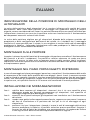
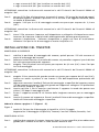
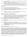
1
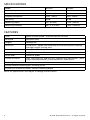
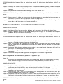
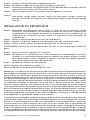
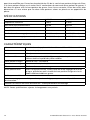
C o m p o n e n t S p eaker MODEL HCCA52 HCCA62 OWNER'S MANUAL Table of Contents English . . . . . . . . . . . . . . . . . . . . . . . . . . . . . . . . . . . . . . . . . . . . . . . . . . . . . . . . . . . . . . . . . . . . . . . . . 1 Français . . . . . . . . . . . . . . . . . . . . . . . . . . . . . . . . . . . . . . . . . . . . . . . . . . . . . . . . . . . . . . . . 9 Español . . . . . . . . . . . . . . . . . . . . . . . . . . . . . . . . . . . . . . . . . . . . . . . . . . . . . . . . . . . . . . . 13 Deutsch . . . . . . . . . . . . . . . . . . . . . . . . . . . . . . . . . . . . . . . . . . . . . . . . . . . . . . . . . . . . . . . 17 Italiano . . . . . . . . . . . . . . . . . . . . . . . . . . . . . . . . . . . . . . . . . . . . . . . . . . . . . . . . . . . . . . . 21 Português . . . . . . . . . . . . . . . . . . . . . . . . . . . . . . . . . . . . . . . . . . . . . . . . . . . . . . . . . . . . 25 Introduction . . . . . . . . . . . . . . . . . . . . . . . . . . . . . . . . . . . . . . . . . . . . . . . . . . . . . . . . . . . . . . . . . . . . 1 Practice Safe Sound™ . . . . . . . . . . . . . . . . . . . . . . . . . . . . . . . . . . . . . . . . . . . . . . . . . . . . . . . . . . . . 2 What’s in the Box . . . . . . . . . . . . . . . . . . . . . . . . . . . . . . . . . . . . . . . . . . . . . . . . . . . . . . . . . . . . . . . . 2 Tools of the Trade . . . . . . . . . . . . . . . . . . . . . . . . . . . . . . . . . . . . . . . . . . . . . . . . . . . . . . . . . . . . . . . 2 Installation . . . . . . . . . . . . . . . . . . . . . . . . . . . . . . . . . . . . . . . . . . . . . . . . . . . . . . . . . . . . . . . . . . . . . 2 Finding Speaker Mounting Locations . . . . . . . . . . . . . . . . . . . . . . . . . . . . . . . . . . . . . . . . . . . . . . . . 3 Door Mounting . . . . . . . . . . . . . . . . . . . . . . . . . . . . . . . . . . . . . . . . . . . . . . . . . . . . . . . . . . . . . . . . . 3 Rear Deck Mounting . . . . . . . . . . . . . . . . . . . . . . . . . . . . . . . . . . . . . . . . . . . . . . . . . . . . . . . . . . . . . 3 Installing the Mid/Woofers . . . . . . . . . . . . . . . . . . . . . . . . . . . . . . . . . . . . . . . . . . . . . . . . . . . . . . . . 3 Installing the Tweeter . . . . . . . . . . . . . . . . . . . . . . . . . . . . . . . . . . . . . . . . . . . . . . . . . . . . . . . . . . . . 4 Installing the Crossover . . . . . . . . . . . . . . . . . . . . . . . . . . . . . . . . . . . . . . . . . . . . . . . . . . . . . . . . . . . 5 Wiring Diagram . . . . . . . . . . . . . . . . . . . . . . . . . . . . . . . . . . . . . . . . . . . . . . . . . . . . . . . . . . . . . . . . . 6 Specifications . . . . . . . . . . . . . . . . . . . . . . . . . . . . . . . . . . . . . . . . . . . . . . . . . . . . . . . . . . . . . . . . . . . 8 Features . . . . . . . . . . . . . . . . . . . . . . . . . . . . . . . . . . . . . . . . . . . . . . . . . . . . . . . . . . . . . . . . . . . . . . . 8 Warranty . . . . . . . . . . . . . . . . . . . . . . . . . . . . . . . . . . . . . . . . . . . . . . . . . . . . . . . . . . . . . . . back cover Introduction Thank you for your purchase of the Orion HCCA Component Loudspeaker system. These speakers represent a combination of incredible performance and value. The HCCA die-cast components feature Kevlar treated paper cones and silk dome tweeters. Capable of maintaining their balance and clarity at exceptionally high output levels, they are the perfect complement to the HCCA subwoofers. The crossovers feature tweeter level adjustment, and are biampable for extreme system designs. These high-performance components are built with 4 ohm voice coils, to get the most out of your amplifier. The components are available in a standard 5 1/4" and 6-1/2” sizes to fit most applications. We at Orion strive to give you all the latest up to date information about this product. What we can’t give you in this manual is personal installation or technical experience. If you have questions concerning the use or application of this product, please refer to the nearest Authorized Orion Dealer for assistance or call the Orion technical support hot-line at 1-800-876-0800. As we are always finding new ways to improve our product, the features and specifications are subject to change without notice. © 2010 directed electronics—all rights reserved 1 Practice Safe Sound™ Continuous exposure to sound pressure levels over 100dB may cause permanent hearing loss. High powered automotive sound systems can generate sound pressure levels in excess of 130dB. When playing your system at high levels, please use hearing protection and prevent long term exposure. Model Number: _____________________________ Date of Purchase: _____________________________ What’s in the Box Included in this box are all the necessary mounting hardware and cables for your basic installation. Listed below is a detailed list of the components included in this system package. Quantity Description 1Owner's Manual 2 HCCA Tweeter Elements 2Surface mount hardware 2Flush mount hardware 2 HCCA mid/woofer 2 Passive crossovers 4 Cables (speakers to crossover) 4 Cables (crossover to amplifier) 1 Mounting template 2 Grilles Mounting screws Tools of the Trade Listed are the majority of the tools required to perform the installation. Having the proper tools will make the installation much easier. It is very difficult when you get half way through the installation and discover that you require a specific tool to get yourself through a particular part of the installation. Some of these tools are necessities. Some make the job much easier. o o o o o o o o o Marking Pen o Electric Drill 1/4" Drill Bit o Phillips Screwdriver 1/8" Drill Bit o Volt/Ohm Meter (Optional) 3/8" Drill Bit o Needle Nose Pliers Hole Saw Arbor o Assorted Tin Snips Wire Crimpers o Wire Strippers 5-5/8" Hole Saw (6-1/2" woofer install.) 4-3/4" Hole Saw (5-1/4" mid/woofer install.) 2" or 2-1/8" Hole Saw (for flush mount tweeter installation.) Installation The performance of the HCCA Component Loudspeaker is directly proportional to the quality of installation. Care taken during the installation process will be rewarded with years of satisfying performance. If you are unsure about your installation capabilities, please refer to your local Authorized Orion Dealer for technical assistance. Orion dealers are trained professionals dedicated to extracting the maximum performance out of your Orion system. If you decide to install this speaker system yourself, please read the entire installation section before starting your installation. 2 © 2010 directed electronics—all rights reserved Finding Speaker Mounting Locations Choosing the correct speaker locations will have the greatest effect on the sound quality of the system. Different considerations are needed when choosing the locations that best suit your needs. The locations must be large enough for the speakers to fit. Care is needed to ensure that the location you have chosen will not affect any of the mechanical or electrical operations of the vehicle. Determining the best location for the speakers will depend on your cosmetic needs and your vehicle's interior. If minimal intrusion in your vehicle is desired, factory speaker locations may be the ticket for you. Placing the speaker in the factory location can often give very desirable results. Door Mounting When checking for possible speaker locations in the doors, check the operation of the window and all assemblies. There is also a stabilizer stop bar in between the door and the door jamb. This bar prevents the door from opening too far. Many shade tree installers overlook this and check for clearance only when the door is fully open. Rear Deck Mounting In rear deck installations, check the operation of the trunk suspension springs or tension bars. These tension bars move in the opening and closing of the trunk. You cannot be too cautious during this part of the installation, In addition, do not locate the speakers too close to the back of the rear deck. Installing the far screws will only be possible with the removal of the rear window. Installing the Mid/Woofers Step 1: Determine where the speakers will be mounted. Make sure there is a flat area large enough for the speakers to fit properly. An uneven mounting surface can damage the driver. Step 2: Check to make sure the space you have chosen for the speakers will not interfere with the operation of the vehicle. Step 3:Using the supplied template guide, mark the mounting hole and mounting screw hole locations with a pen for each speaker. Step 4: Cut the holes for the speaker. When using correctly sized factory locations, this step can be passed. A hole can be cut either with a pair of metal tin snips, an air or jig saw, or with a hole saw corresponding to the size of the midrange listed below. • 5-5/8” Hole Saw (6-1/2” mid/woofer installation) • 4-3/4" Hole Saw (5-1/4" mid/woofer install.) WARNING: Check for clearance of window mechanisms and electrical wires BEFORE you drill. Step 5: Run the speaker wire to the speakers. Make sure to keep wires away from sharp metal or other edges. When passing through metal, use a protective grommet. Step 6: Pre-drill mounting screw holes using a 1/8" drill bit. WARNING: Check for clearance of window mechanisms and electrical wires BEFORE you drill. © 2010 directed electronics—all rights reserved 3 Step 7: Pull the wire through the speaker opening and connect to the speaker. Be sure to observe proper mid/woofer polarity during this process. Step 8: Mount the speaker- Place the speaker and the grille in the installation hole. Align the mounting screw holes and drive in the four mounting screws. Installing the Tweeter SURFACE MOUNTING Step 1: Determine the tweeter mounting location, then route the wires from the crossover to the tweeter location. Step 2: Place the provided template or tweeter cup against the panel and mark the two holes at the rear of the housing. Step 3: Drill the smaller holes using a 1/8" drill bit. These are the mounting screw holes. WARNING: Check for clearance of window mechanisms and electrical wires BEFORE you drill. Step 4: Drill the larger off-center hole using a 3/8" drill bit, insert a grommet and route the speaker wire from the crossover through the grommet. Step 5:After removing the surface mount tweeter assembly trim ring, route the tweeter wires through the larger hole in the housing and connect to the speaker wires from the crossover. (See Figure 4.) Step 6: Insert the excess speaker wire into the hole and position the housing so the housing will not pinch the wires after final mounting. Step 7:Attach the housing using the supplied screws of the correct length for a solid mount. Step 8: Insert the tweeter into the housing and attach the surface mount trim ring. SURFACE MOUNT TRIM RING Figure 2 Figura 2 Abbildung 2 4 MOUNTING SCREWS TWEETER TWEETER WIRE SURFACE MOUNT HOUSING PANEL WIRING HARNESS © 2010 directed electronics—all rights reserved FULL FLUSH MOUNTING Step 1:. Determine where the tweeter will be mounted. Make sure there is a flat area large enough for the tweeter and no obstructions behind the area. Step 2:Using the back half of the tweeter housing, mark with a pen the hole needed for the tweeter. Step 3:Be sure the hole is large enough for the tweeter housing, but not so large that the flange will not cover the hole.. Step 4: Cut the hole for the tweeter. When using factory locations, this step can be skipped. A hole can be cut either with a pair of metal tin snips or a 2" hole saw for hard materials. WARNING: Check for clearance of window mechanisms and electrical wires BEFORE you drill. Step 5: Install tweeter in flush mount housing. Step 6: Connect the speaker wires observing the correct polarity. Step 7: Install tweeter and housing in the hole cut for mounting, so that the trim ring is flat with the front of the surface. Step 8: Use the supplied pressure ring to secure the housing to the surface. TWEETER CUP TWEETER Figure 3 Figura 3 Abbildung 3 FLUSH MOUNT TRIM RING TWEETER WIRE PRESSURE RING PANEL WIRING HARNESS Installing the Crossover Step 1:Find a location for the crossover away from any factory or after market electrical wires. It is recommended to mount the passive crossover close to the amplifier. In the event you decide to upgrade and bi-amplify the system, mounting the passive crossover close to the amplifier would simplify the installation upgrade. Step 2: Remove top cover of crossover housing. Don’t lose it. Step 3: Mark with a marking pen the two mounting holes. Step 4: Remove crossover and pre-drill mounting holes using a 1/8” drill bit. WARNING: Check for clearance of window mechanisms and electrical wires BEFORE you drill. Step 5: Mount the crossover using the supplied #8 screws. © 2010 directed electronics—all rights reserved 5 Step 6: Connect the wires. Make sure the speaker wires for the mid/woofer go to the woofer output and the tweeter to the tweeter output. Be sure to observe the correct polarity. Changing the polarity of the tweeter may be necessary for optimum sound quality. Step 7: Re-install the crossover cover. NOTE: The crossover has a parallel and a bi-wire/bi-amp input. To access these settings remove the top cover of the crossover. This is accomplished with a small flat head screw driver. There is a small notch just to the left of the output plug on the crossover. Insert the screwdriver and gently pry. Be very cautious not to insert the screwdriver too far or you could cause physical damage to the board and void your warranty. The parallel/bi-wire switch is right next to the input plug. When selecting parallel, it does just that, wires the input in parallel (meaning the positive terminals are common and the negative terminals are common). You would use this selection when using a single channel to power the tweeter and the mid/woofer. It does not matter which positive and which negative you use since they are wired in parallel, although the tweeter positive and woofer negative are on opposite ends of the plug to make the wiring easier. Parallel wiring is also probably the most popular wiring method. The bi-wire/bi-amp selection is for using two separate channels for powering the tweeter and the mid/woofer. When using this selection one channel would use the positive and negative for the tweeter and the other channel would use the positive and negative for the mid/ woofer. There is also a tweeter level switch for adjusting the tweeter. Moving this adjustment will change the output gain of the tweeter. Where the adjustment should be depends on the location of the tweeter and your preference. Adjustments can be made from +3dB to -6dB in 3 dB steps. Tweeter phase can be changed by reversing the polarity of the tweeter output wire connections on the crossover. If the tweeter is within 6" of the woofer center the tweeter should be in phase with the woofer. If the tweeter is further than 6" from the center of the woofer, both in phase and out of phase should be tried to see which is best Parallel Wiring Figure 4 Figura 4 Abbildung 4 To woofer _ + input - output + _ To tweeter + + _ 6 © 2010 directed electronics—all rights reserved Bi-Amp Wiring Figure 5 Figura 5 Abbildung 5 To woofer _ + ww+ T- input output T+ _ To tweeter + + _ + _ Note: The tweeter positive is the wire marked with the stripe. Note: Le câble positif du haut-parleur d'aigus est rayé. Nota. El positivo del tweeter es el cable que tiene la franja. Hinweis: Der positive Hochtönerdraht ist mit dem Streifen markiert. Nota: il filo positivo del tweeter è contrassegnato da una striscia. Nota: O cabo positivo do tweeter está marcado com a listra. © 2010 directed electronics—all rights reserved 7 Specifications Model HCCA52 HCCA62 Nominal Impedance 4 ohms 4 ohms Power Continuous/Maximum 50/100 60/120 Frequency Response 75Hz - 20kHz 55Hz - 20kHz Sensitivity 85 dB 86 dB Mounting Depth 1.9" (49 mm) 2.125" (54mm) Mounting Diameter 4.6" (116.5 mm) 5.625" (143mm) Features Cone paper & Kevlar blend – moisture and UV resistant Surround polyester foam Magnet Neodymium Voice Coil CCAW wire – copper clad aluminum wire for best power handling and light weight moving parts Tweeter dome–silk - Ferrofluid Spider single flat interlaced Conex Tinsel leads woven to spider Custom crossover with 12dB high pass, 6dB low pass, tweeter level adjustments, multi stage tweeter protection, and mid/mid-bass zobel circuit. Custom grills Custom tweeter mounting kits including swivel Custom Cast Aluminum Basket: Shallow mounting depth NOTE: All Specifications are subject to change without notice. 8 © 2010 directed electronics—all rights reserved FRANÇAIS OÙ MONTER LES HAUT-PARLEURS Le choix du bon emplacement des haut-parleurs aura un effet majeur sur la qualité du son du système. Plusieurs choses doivent être prises en considération pour faire le meilleur choix. Les emplacements doivent être assez grands pour accueillir les haut-parleurs. Faites attention que l'emplacement choisi n'affecte en aucune façon le fonctionnement mécanique et électrique du véhicule. Le meilleur emplacement pour les haut-parleurs dépend de vos goûts et de l'aménagement intérieur du véhicule. Si vous voulez une installation aussi discrète que possible, les emplacements prévus par le fabricant sont sans doute le meilleur choix. Cela donnera souvent d'excellents résultats. MONTAGE SUR UNE PORTIÈRE Quand vous recherchez une location possible pour installer vos haut-parleurs dans les portières, vérifiez le fonctionnement de la fenêtre et de tous les mécanismes. Vérifiez aussi la barre stabilisatrice entre la portière et son montant. Elle empêche la portière de s'ouvrir trop grand. Beaucoup d'installateurs inexpérimentés négligent ce détail et ne vérifient l'espace libre que quand la porte est grand ouverte. MONTAGE DANS LE COFFRE Pour une installation dans le coffre, vérifiez le fonctionnement des ressorts de suspension ou barres de tension du coffre. Ces barres se déplacent durant l'ouverture et la fermeture du coffre. On n'est jamais trop prudent durant cette partie de l'installation. De plus, ne placez pas les hautparleurs trop près de l'arrière du coffre. L'installation des vis les plus écartées n'est possible que si on retire la vitre arrière. INSTALLATION DES HAUT-PARLEURS MÉDIAUX ET DE GRAVES Étape 1: Décidez où fixer les haut-parleurs et assurez-vous qu'il y ait une surface plane suffisante pour bien les fixer. Une surface de montage inégale peut endommager le moteur. Étape 2: Assurez-vous que l'emplacement choisi pour les haut-parleurs n'interfère pas avec le fonctionnement du véhicule. Étape 3: Au moyen du gabarit de montage fourni et d'un crayon, marquez l'emplacement des trous de montage et des vis de montage pour chaque haut-parleur. Étape 4: Découpez les trous pour le haut-parleur. Si vous utilisez les emplacements prévus par le fabricant et qu'ils sont de la bonne dimension, cette étape peut être sautée. Utilisez soit une paire de cisailles à tôles, une scie pneumatique ou sauteuse, ou une scie-cloche de la taille correspondant à celle ci-dessous. o Scie-cloche 5-5/8” (installation d'un haut-parleur de graves de 6-1/2”) o Scie-cloche 4-3/4" (installation d'un haut-parleur de graves de 5-1/4") © 2010 directed electronics—Tous droits réservés 9 ATTENTION: Vérifiez l'espace libre du mécanisme et des fils électriques des fenêtres AVANT de percer. Étape 5: Amenez les câbles à leurs haut-parleurs. Assurez-vous de les garder loin de tout bord métallique ou autre aiguisé. Pour passer à travers le métal, utilisez une rondelle isolante. Étape 6: Pré-percez les trous de vis de montage avec une mèche 1/8". ATTENTION: Vérifiez l'espace libre du mécanisme et des fils électriques des fenêtres AVANT de percer. Étape 7: Faites passer le câble par l'ouverture du haut-parleur et raccordez-le. Assurez-vous de respecter la polarité du haut-parleur médial et de graves. Étape 8: Montez le haut-parleur — Placez-le avec sa grille dans le trou d'installation. Alignez les trous des vis de montage et vissez les quatre vis. INSTALLATION DU HAUT-PARLEUR D'AIGUS MONTAGE EN SURFACE Étape 1: Décidez où fixer le haut-parleur d'aigus, puis amenez-y les câbles du répartiteur. Étape 2: Placez le gabarit fourni ou le cône du haut-parleur d'aigus sur le panneau et marquez les deux trous à l'arrière du logement. Étape 3: Percez les petits trous avec une mèche 1/8". Ce sont les trous de montage. ATTENTION: Vérifiez l'espace libre du mécanisme et des fils électriques des fenêtres AVANT de percer. Étape 4: Percez le grand trou excentré (mèche de 3/8"), insérez une rondelle isolante et faites-y passer le câble du haut-parleur vers le répartiteur. Étape 5: Ôtez la garniture de montage en surface, passez les câbles du haut-parleur d'aigus par le grand trou du logement et raccordez aux câbles de haut-parleur du répartiteur (figure 4.) Étape 6: Insérez le câble de haut-parleur en trop dans le trou et placez le logement afin qu'il ne pince pas les câbles après le montage final. Étape 7: Pour un montage solide, utilisez les vis fournies de la bonne longueur pour attacher le logement. Étape 8: Insérez le haut-parleur d'aigus dans le logement et attachez la garniture. NOTE: Diagramme de référence aux pages 4 - 7 (figure 1 - 5) Figure 2 Enjoliveur De Montage En Surface, Vis De Montage, Boîtier De Montage En Surface, Haut-Parleur D’aigus, Fil De Haut-Parleur D’aigus, Panneau, Faisceau De Fils. MONTAGE ENCASTRÉ Étape 1: Décidez où fixer le haut-parleur d'aigus et assurez-vous qu'il y ait une surface plane suffisante pour bien le fixer, sans obstructions à l'arrière de la surface. Étape 2: Marquez le trou de montage nécessaire à l'aide d'un crayon et de la moitié arrière du logement du haut-parleur. Étape 3: Assurez-vous que le trou est assez grand pour le logement du haut-parleur, mais pas trop grand pour être couvert par la flasque. Étape 4: Coupez le trou du haut-parleur (inutile si vous utilisez les emplacements prévus par le fabricant). Utilisez des cisailles à tôles ou une scie-cloche 2" pour les matériaux durs. ATTENTION: Vérifiez l'espace libre du mécanisme et des fils électriques des fenêtres AVANT de percer. 10 © 2010 directed electronics—Tous droits réservés Étape 5: Installez le haut-parleur dans le logement encastré. Étape 6: Raccordez les câbles du haut-parleur en respectant la polarité. Étape 7: Installez le haut-parleur et le logement dans le trou découpé pour le montage, afin que la garniture soit au niveau de l'avant de la surface. Étape 8: Utilisez l'anneau de pression inclus pour fixer le logement à la surface. Figure 3 Haut-parleur d’aigus monté encastré, Boîtier du haut-parleur d’aigus, anneau de pression, Faisceau de fils, Panneau, Fil de haut-parleur d’aigus, Enjoliveur de montage encastré. INSTALLATION DU RÉPARTITEUR Étape 1: Déterminez un emplacement pour le filtre, à l’écart de tout fil électrique installé en usine ou ultérieurement. Il est conseillé de monter le filtre passif à proximité de l’amplificateur. Si vous décidez d’améliorer le système grâce à la bi-amplification, la modification de l’installation sera plus simple si le filtre passif a été monté près de l’amplificateur. Étape 2 : Retirez le couvercle du boîtier du filtre. Ne le perdez pas. Étape 3 : Repérez à l’aide d’un marqueur les emplacements des deux trous de montage. Étape 4 : Retirez le filtre et percez les trous de montage avec un foret de 3 mm. AVERTISSEMENT: Vérifiez les jeux des mécanismes de vitres et des fils électriques AVANT de percer. Étape 5: Montez le filtre à l’aide des vis n° 8 fournies. Étape 6: Raccordez les fils. Vérifiez que les fils du haut-parleur de médiums/graves sont bien raccordés à la sortie haut-parleur de graves et ceux du haut-parleur d’aigus à la sortie haut-parleur d’aigus. Veillez à respecter la polarité. L’inversion de la polarité peut être nécessaire à l’optimisation de la qualité du son. Étape 7: Remettez le couvercle du filtre en place. NOTE: Diagramme de référence aux pages 6 - 7. NOTE: Le câble positif du haut-parleur d'aigus est rayé. REMARQUE : L’entrée du filtre peut être configurée en parallèle et en bi-câblage/bi-amplification. Pour accéder à ces réglages, retirez le capot du filtre. Utilisez pour cela un petit tournevis plat. Une petite encoche se trouve juste à gauche du connecteur de sortie du filtre. Insérez-y le tournevis et soulevez doucement. Faites très attention à ne pas insérer le tournevis trop profondément, car cela pourrait endommager la carte et annuler la garantie. Le commutateur parallèle/bi-câblage se trouve juste à côté du connecteur d’entrée. Lorsque le mode parallèle est sélectionné, l’entrée est simplement raccordée en parallèle (c’est-à-dire que les bornes positives sont reliées entre elles et les bornes négatives sont reliées entre elles). Cette configuration est utilisée lorsqu’un canal unique alimente le haut-parleur d’aigus et le haut-parleur de médiums/graves. Toute borne positive et toute borne négative peuvent être utilisées, en raison du câblage parallèle ; toutefois, la borne positive du haut-parleur d’aigus et la borne négative du haut-parleur de graves sont aux extrémités opposées du connecteur, ce qui facilite le câblage. D’autre part, le câblage parallèle est probablement la méthode de câblage la plus courante. La configuration bi-câblage/bi-amplification permet d’utiliser deux canaux distincts pour alimenter le haut-parleur d’aigus et le haut-parleur de médiums/graves. Dans cette configuration, la borne positive et la borne négative d’un canal sont utilisées pour le haut-parleur d’aigus, tandis que la borne positive et la borne négative de l’autre canal sont utilisées pour le haut-parleur de médiums/graves. En outre, un commutateur de niveau d’aigus permet le réglage du haut-parleur d’aigus. Ce réglage permet de modifier le gain de sortie vers le haut-parleur d’aigus. Le réglage à utiliser dépend de l’emplacement du haut-parleur d’aigus et des préférences de l’utilisateur. Les réglages disponibles vont de +3 dB à –6 dB par pas de 3 dB. La phase du haut-parleur d’aigus © 2010 directed electronics—Tous droits réservés 11 peut être modifiée par l’inversion de polarité des fils de la sortie haut-parleur d’aigus du filtre. Si le haut-parleur d’aigus est à moins de 15 centimètres du centre du haut-parleur de graves, il doit être en phase avec le haut-parleur de graves. Dans le cas contraire, faites des essais pour déterminer s’il vaut mieux que les deux haut-parleurs soient en phase ou en opposition de phase. SPÉCIFICATIONS Modèle HCCA52 HCCA62 Impédance nominale 4 ohm 4 ohm Puissance continue/maximum 50/100 60/120 Réponse de fréquence 75Hz - 20kHz 55Hz - 20kHz Sensitivité 85 dB 86 dB Profondeur de montage (pouces/mm) 1.9" (49 mm) 2.125" (54mm) Diamètre de montage (pouces/mm) 4.6" (116.5 mm) 5.625" (143mm) CARACTÉRISTIQUES Cône Combinaison de papier et Kevlar résistant à l’humidité et aux UV Boîtier Mousse de polyester Aimant Néodyme Bobine mobile Fil d’aluminium cuivré (CCAW) pour optimiser la puissance admissible et réduire le poids des pièces mobiles Haut-parleur d'aigus Dôme de soie – Ferrofluid Anneau de centrage Conex entrelacé plat simple Fils rosettes Tissés sur l’anneau de centrage Filtre personnalisé Avec filtrage passe-haut 12 dB, passe-bas 6 dB, réglages de niveau d’aigus, protection multi-niveau du haut-parleur d’aigus et circuit Zobel médiums/médiums-graves Grilles personnalisées Kits de montage personnalisé pour haut-parleur d’aigus, comprenant un dispositif d’orientation. Saladier sur mesure en fonte d’aluminium : faible profondeur de montage NOTE: Toutes spécifications sujettes à changement sans préavis. 12 © 2010 directed electronics—Tous droits réservés ESPAÑOL UBICACIONES DE MONTAJE DE LOS ALTAVOCES Escoger la ubicación correcta de los altavoces tendrá el mayor efecto en la calidad del sonido del sistema. Es necesario que usted tenga en cuenta varias consideraciones cuando escoja el lugar que mejor se adapte a sus necesidades. Los lugares escogidos deben ser lo suficientemente grandes como para que quepan los altavoces. Es necesario que en la ubicación escogida no se afecte ninguna operación mecánica o eléctrica del vehículo. Determinar la mejor ubicación de los altavoces depende de sus necesidades cosméticas y del interior del vehículo. Si desea interferir lo menos posible con el vehículo, las ubicaciones de altavoz de fábrica son ideales. Colocar el altavoz en la ubicación de fábrica puede a menudo dar muy buenos resultados. MONTAJE EN LA PUERTA Cuando esté buscando posibles ubicaciones de altavoz en las puertas, verifique el funcionamiento de las ventanas y de todos los mecanismos de las puertas. También hay una barra de tope estabilizadora entre la puerta y la jamba de la puerta. Esta barra evita que la puerta se abra demasiado. Muchos instaladores informales olvidan esto y verifican que haya espacio sólo cuando la puerta está completamente abierta. MONTAJE EN LA REPISA TRASERA En las instalaciones en repisa trasera, verifique el funcionamiento de los resortes de suspensión o barras de tensión de la tapa del maletero. Estas barras de tensión se mueven cuando se abre o se cierra el maletero. Ser precavido nunca está de más durante esta parte de la instalación. Además, no ubique los altavoces demasiado cerca del fondo de la repisa trasera. Montar los tornillos del fondo será posible solamente quitando la ventana trasera. INSTALACIÓN DE LOS ALTAVOCES DE FRECUENCIAS MEDIAS Y BAJAS Paso 1: Determine el lugar en que va a montar los altavoces. Debe haber una superficie plana suficientemente grande como para que los altavoces encajen correctamente. Las superficies de montaje irregulares pueden dañar el excitador. Paso 2: Verifique que, en el lugar escogido, el altavoz no interfiera con el funcionamiento del vehículo. Paso 3: Con la plantilla guía suministrada y un lápiz, marque el agujero de montaje del altavoz y los agujeros de los tornillos de montaje de los altavoces. Paso 4: Haga los agujeros para los altavoces. Cuando instale los altavoces en ubicaciones de fábrica, este paso se puede omitir. El agujero se puede hacer con unas tijeras para cortar metal, una sierra caladora o una sierra circular que corresponda al tamaño del altavoz de frecuencias medias que se indica abajo. © 2010 directed electronics—Reservados todos los derechos. 13 * Sierra circular de 5-5/8 plg. (woofer de 6-1/2 plg.) * Sierra circular de 4-3/4 plg. (woofer de 5-1/4 plg.) ADVERTENCIA: Verifique que haya espacio para los mecanismos de ventana y los cables eléctricos ANTES de taladrar. Paso 5:Encamine el cable de altavoz hasta los altavoces. Mantenga los cables de altavoz lejos de los bordes afilados de metal u otro material. Cuando pase los cables a través de metal, ponga en el agujero una arandela de goma protectora. Paso 6: Haga de antemano los agujeros de montaje con una broca perforadora de 1/8 de plg. ADVERTENCIA: Verifique que haya espacio para los mecanismos de ventana y los cables eléctricos ANTES de taladrar. Paso 7: Jale el cable a través de la abertura del altavoz y conéctelo al altavoz. Mantenga la polaridad correcta de los altavoces de frecuencias medias y bajas durante este proceso. Paso 8: Monte el altavoz. Coloque el altavoz y la rejilla en el agujero de instalación. Alinee los agujeros de los tornillos de montaje y atornille los cuatro tornillos de montaje. Instalación del Tweeter MONTAJE EN SUPERFICIE Paso 1: Determine la ubicación de montaje del tweeter y luego encamine los cables provenientes del crossover hasta la ubicación del tweeter. Paso 2: Ponga la plantilla suministrada o la copa del tweeter contra el panel y marque los dos agujeros en la parte de atrás del alojamiento. Paso 3: Haga los agujeros pequeños con una broca de 1/8 plg. Estos son los agujeros de los tornillos de montaje. ADVERTENCIA: Verifique que haya espacio para los mecanismos de ventana y los cables eléctricos ANTES de taladrar. Paso 4: Haga el agujero grande excéntrico con una broca perforadora de 3/8 plg., inserte una arandela de goma y encamine el cable de altavoz proveniente del crossover a través de la arandela de goma. Paso 5. Después de quitar el anillo de guarnición de la unidad de tweeter para montaje en superficie, encamine los cables del tweeter a través del agujero grande que hay en el alojamiento y conecte los cables de altavoz provenientes del crossover (vea la Figura 4). Paso 6. Inserte el exceso de cable de altavoz en el agujero y ponga en posición el alojamiento de manera que no vaya a aplastar los cables después del montaje final. Paso 7. Fije el alojamiento con los tornillos suministrados de la longitud correcta para lograr un montaje sólido. Paso 8. Inserte el tweeter en el alojamiento y fije el anillo de guarnición de montaje en superficie. Consulte el diagrama de las páginas 4 - 7 (figura 1 - 5) Figura 2 Anillo De Guarnición De Montaje En Superficie, Tornillos De Montaje, Alojamiento De Montaje En Superficie, Tweeter, Cable De Tweeter, Panel, Arnés De Cableado. MONTAJE AL RAS Paso 1. Determine dónde va a montar el tweeter. Debe haber una superficie plana lo suficientemente grande como para que quepa el tweeter y no debe haber obstrucciones 14 © 2010 directed electronics—Reservados todos los derechos. detrás. Paso 2. Con la parte de atrás del alojamiento del tweeter y un lápiz, marque el agujero necesario para el tweeter. Paso 3.El agujero debe ser lo suficientemente grande como para que quepa el alojamiento del tweeter, pero no tanto que el reborde no cubra el agujero. Paso 4. Haga el agujero para el tweeter. Cuando instale el tweeter en ubicaciones de fábrica, este paso se puede omitir. Se puede hacer el agujero con unas tijeras de metal o una sierra circular de 2 plg. para materiales duros. ADVERTENCIA: Verifique que haya espacio para los mecanismos de ventana y los cables eléctricos ANTES de taladrar. Paso 5. Instale el tweeter en el alojamiento de montaje al ras. Paso 6. Conecte los cables de altavoz con la polaridad correcta. Paso 7. Instale el tweeter y el alojamiento en el agujero de montaje de manera que el anillo de guarnición quede de plano contra la superficie exterior. Paso 8. Con el anillo de presión suministrado, asegure el alojamiento contra la superficie. Figura 3 Unidad de tweeter de montaje al ras, Copa de tweeter, anillo de presión, Arnés de cableado, Panel, Cable de tweeter, Anillo de guarnición de montaje al ras. INSTALACIÓN DEL CROSSOVER Paso 1: Busque una ubicación para el crossover lejos de los cables eléctricos de fábrica o instalados después. Se recomienda montar el crossover pasivo cerca del amplificador. Si decide mejorar el sistema y hacer amplificación doble, montar el crossover pasivo cerca del amplificador simplifica el mejoramiento de la instalación. Paso 2: Quite la tapa de arriba del alojamiento del crossover. No la pierda. Paso 3: Marque con un marcador los puntos donde va a hacer los dos agujeros de montaje. Paso 4: Quite el crossover y haga agujeros piloto de montaje con una broca de 1/8 de pulgada. ADVERTENCIA: Vea si hay espacio para la broca entre los mecanismos y los cables eléctricos de la ventana ANTES de taladrar. Paso 5: Monte el crossover con los tornillos Nº 8 incluidos. Paso 6: Conecte los cables. Los cables de altavoz para el altavoz de frecuencias medias y bajas van a la salida de woofer y los del tweeter a la salida de tweeter. Mantenga la polaridad correcta. Puede ser necesario cambiar la polaridad del tweeter para obtener una calidad de sonido óptima. Paso 7: Vuelva a instalar la tapa del crossover Consulte el diagrama de las páginas 6 - 7. NOTA. El positivo del tweeter es el cable que tiene la franja. NOTA: El crossover tiene una entrada paralela y una entrada de cableado doble y amplificación doble. Para alcanzar estas entradas, quite la cubierta superior del crossover. Esto se logra con un destornillador pequeño de cabeza plana. Hay una pequeña muesca a la izquierda del enchufe de salida del crossover. Inserte el destornillador y haga palanca ligeramente. Tenga mucho cuidado de no insertar demasiado el destornillador porque puede dañar físicamente el circuito impreso y anular la garantía. El selector de cableado paralelo o cableado doble está al lado del enchufe de entrada. Cuando se selecciona la opción de cableado en paralelo, se produce exactamente eso, los cables de entrada quedan conectados en paralelo (lo cual significa que las terminales positivas son comunes y las terminales negativas son comunes). Se utiliza esta opción cuando hay un solo canal para alimentar el tweeter y el altavoz de frecuencias medias y bajas. No importa qué terminal positiva ni qué terminal negativa utilice porque están conectadas en paralelo, aunque la terminal positiva del tweeter y la negativa del woofer están en lados opuestos del © 2010 directed electronics—Reservados todos los derechos. 15 enchufe para facilitar el cableado. Además, el cableado en paralelo es probablemente el método más popular de cableado. La opción de cableado doble y amplificación doble es para alimentar el tweeter y el altavoz de frecuencias medias y bajas por canales separados. Cuando escoja esta opción, un canal se utiliza para la terminal positiva y la terminal negativa del tweeter y el otro canal para la terminal positiva y la terminal negativa del altavoz de frecuencias medias y bajas. También hay un selector de nivel para ajustar el tweeter. Este ajuste cambia la amplificación de salida del tweeter. El ajuste depende de la ubicación del tweeter y de la preferencia personal del oyente. Hay ajustes de +3 dB a -6 dB en incrementos de 3 dB. La fase del tweeter se puede cambiar invirtiendo la polaridad de las conexiones del cable de salida del tweeter en el crossover. Si el tweeter está a menos de 6 plg. de distancia del centro del woofer, el tweeter debe estar en fase con el woofer. Si el tweeter está a más de 6 plg. de distancia del centro del woofer, se puede probar la conexión en fase y la conexión fuera de fase para ver cuál suena mejor. ESPECIFICACIONES Modelo HCCA52 HCCA62 Impedancia nominal 4 ohm 4 ohm Potencia continua/máxima 50/100 60/120 Respuesta de frecuencias 75Hz - 20kHz 55Hz - 20kHz Sensibilidad 85 dB 86 dB Profundidad de montaje (plg/mm) 1.9" (49 mm) 2.125" (54mm) Diámetro de montaje (plg/mm) 4.6" (116.5 mm) 5.625" (143mm) Características Cono combinación de papel y Kevlar resistente a la humedad y los rayos ultravioleta Envolvente espuma de poliéster Imán neodimio Bobina de voz Cable de Aluminio Revestido con Cobre (Copper Clad Aluminum Wire, CCAW) para obtener el mejor procesamiento de potencia posible y para que las piezas móviles sean livianas Tweeter Domo de seda - Ferrofluido Araña Conex entrelazado plano de una pieza Conductores de oropel entretejidos en la araña Crossover a la medida con pasaaltas de 12 dB, pasabajas de 6 dB, ajuste de nivel de tweeter, protección de tweeter de varias etapas y circuito Zobel de frecuencias medias y medias bajas Rejillas a la medida Kits de montaje de tweeter a la medida con plataforma giratoria Canasta de aluminio troquelado a la medida: baja profundidad de montaje NOTA: Todas las especificaciones están sujetas a cambios sin aviso previo. 16 © 2010 directed electronics—Reservados todos los derechos. DEUTSCH SO PLATZIEREN SIE DIE LAUTSPRECHER Die Wahl der korrekten Lautsprecherposition hat große Auswirkungen auf die Soundqualität des Systems. Bei der Wahl der Lautsprecherposition, die Ihren Ansprüchen am besten entspricht, sind mehrere Faktoren zu beachten. Es muss an der Stelle genügend Platz für den Lautsprecher vorhanden sein. Sie müssen sicherstellen, dass die gewählte Stelle die mechanischen oder elektrischen Funktionen des Fahrzeugs nicht beeinträchtigt. Die Wahl der geeigneten Einbaustelle hängt sowohl von ästhetischen Faktoren als auch vom Innenraum Ihres Fahrzeugs ab. Wenn Sie das Fahrzeug nur minimal verändern wollen, sind die werksseitigen Einbaustellen am besten. Der Einbau an diesen Stellen kann oft zu sehr guten Ergebnissen führen. TÜREINBAU Wenn Sie mögliche Lautsprechereinbaustellen in den Türen suchen, müssen Sie die Funktionen der Fenster und aller Baugruppen beachten. Zwischen der Tür und der Türschwelle befindet sich eine Stabilisator-Anschlagleiste. Diese Leiste verhindert, dass die Tür sich zu weit öffnet. Viele Amateur-Einbauer übersehen das und prüfen nur den Freiraum bei voll geöffneter Tür. EINBAU IM KOFFERRAUM Beim Einbau im Kofferraum ist auf die Funktionsfähigkeit der Kofferraumfedern oder Zugstäbe zu achten. Diese Zugstäbe bewegen sich beim Öffnen und Schließen des Kofferraums. Seien Sie bei diesem Teil der Installation besonders vorsichtig und platzieren Sie die Lautsprecher auch nicht zu nahe an der Kofferraumhinterkante. Der Einbau der hinteren Schrauben ist erst nach Ausbau des Rückfensters möglich. EINBAU DER MITTEL-/TIEFTÖNER 1. Schritt: Legen Sie fest, wo die Lautsprecher eingebaut werden. Vergewissern Sie sich, dass eine für den fachgemäßen Einbau ausreichende ebene Fläche vorhanden ist. Eine unebene Oberfläche kann den Treiber beschädigen. 2. Schritt: Stellen Sie sicher, dass die gewählte Stelle den Betrieb des Fahrzeugs auf keine Weise behindert. 3. Schritt: Verwenden Sie die beiliegende Schablone und markieren Sie das Einbauloch und die Positionen der Befestigungsschrauben für jeden Lautsprecher mit einem Stift. 4. Schritt: Schneiden Sie das jeweilige Loch für den Lautsprecher aus. Bei Verwendung der werksseitigen Einbaustellen (die schon die richtige Größe haben) kann dieser Schritt übersprungen werden. Man kann das Loch entweder mit einer Blechschere, einer Pressluftsäge oder einer Stichsäge ausschneiden, je nach Größe des unten aufgelisteten Mitteltöners. * 5-5/8 Zoll Lochsäge (6-1/2 Zoll Tieftönerinstallation) * 4-3/4 Zoll Lochsäge (5-1/4 Zoll Tieftönerinstallation) © 2010 directed electronics—Alle Rechte vorbehalten 17 WARNUNG: Prüfen Sie VOR dem Bohren, dass Sie keine Fenstermechanismen oder Stromkabel anbohren. 5. Schritt: Verlegen Sie die Lautsprecherkabel zu den Lautsprechern. Dabei müssen Sie die Kabel von scharfen Metallkanten oder anderen Kanten entfernt halten. Bei der Verlegung durch Metall ist eine Schutztülle zu verwenden. 6. Schritt: Bohren Sie die Befestigungsschraubenlöcher mit einem 1/8-Zoll-Bohrer vor. WARNUNG: Prüfen Sie VOR dem Bohren, dass Sie keine Fenstermechanismen oder Stromkabel anbohren. 7. Schritt: Ziehen Sie das Kabel durch die Lautsprecheröffnung und schließen Sie es an den Lautsprecher an. Beachten Sie dabei, dass die Mitteltöner/Tieftöner richtig gepolt sind. 8. Schritt: Bauen Sie den Lautsprecher ein. Platzieren Sie hierzu den Lautsprecher und den Grill in der Einbauöffnung. Richten Sie die Befestigungsschraubenlöcher aus und ziehen Sie die vier Befestigungsschrauben an. Einbau des Hochtöners OBERFLÄCHENEINBAU 1. Schritt: Legen Sie den Einbauort des Hochtöners fest und verlegen Sie dann die Kabel von der Crossover-Einheit zum Einbauort. 2. Schritt: Legen Sie die beiliegende Schablone oder den Hochtönerbecher auf die Verkleidung und markieren Sie die zwei Löcher an der Rückseite des Gehäuses. 3. Schritt:Bohren Sie die kleineren Löcher mit einem 1/8-Zoll-Bohrer. Das sind die Befestigungsschraubenlöcher. WARNUNG: Prüfen Sie VOR dem Bohren, dass Sie keine Fenstermechanismen oder Stromkabel anbohren. 4. Schritt: Bohren Sie das größere Loch neben der Mitte mit einem 3/8-Zoll-Bohrer, stecken Sie eine Schutztülle ein und verlegen Sie das von der Crossover-Einheit kommende Lautsprecherkabel durch die Schutztülle. 5. Schritt: Nachdem Sie die Blende der Hochtöner-Oberflächeneinbaugruppe entfernt haben, führen Sie die Hochtönerkabel durch das größere Loch im Gehäuse und schließen Sie sie an die von der Crossover-Einheit kommenden Lautsprecherkabel an. (Siehe Abbildung 4.) 6. Schritt: Führen Sie das nicht benötigte Lautsprecherkabel in das Loch ein und platzieren Sie das Gehäuse so, dass es nach dem Endeinbau das Kabel nicht einklemmt. 7. Schritt: Bringen Sie das Gehäuse mit den beiliegenden Schrauben der richtigen Länge an, um eine sichere Befestigung zu gewährleisten. 8. Schritt: Führen Sie den Hochtöner in das Gehäuse ein und bringen Sie die Blende für den Oberflächeneinbau an. Siehe Diagramm auf Seite 4 - 7 (Abbildung 1 - 5). Abbildung 2 Oberflächeneinbau-blendenring, Befestigungsschrauben,Oberflächeneinbaugehäuse Hochtöner, Hochtönerkabel, Platte. BÜNDIGER EINBAU 1. Schritt: Legen Sie die Einbaustelle für den Hochtöner fest. Vergewissern Sie sich, dass eine für den Einbau des Hochtöners ausreichende ebene Fläche vorhanden ist und dass sich dahinter keine Hindernisse befinden. 18 © 2010 directed electronics—Alle Rechte vorbehalten 2. Schritt: Verwenden Sie die Rückseite des Hochtönergehäuses, um das Loch für den Hochtöner mit einem Stift zu markieren. 3. Schritt: Vergewissern Sie sich, dass das Loch für das Hochtönergehäuse groß genug ist, aber nicht so groß, dass der Flansch das Loch nicht mehr abdeckt. 4. Schritt: Schneiden Sie das Loch für den Hochtöner aus. Bei Verwendung der werksseitigen Einbaustellen kann dieser Schritt übersprungen werden. Sie können das Loch entweder mit einer Blechschere oder einer 2-Zoll-Lochsäge für harte Oberflächen ausschneiden. WARNUNG: Prüfen Sie VOR dem Bohren, dass Sie keine Fenstermechanismen oder Stromkabel anbohren. 5. Schritt: Installieren Sie den Hochtöner im bündig eingebauten Gehäuse. 6. Schritt: Schließen Sie die Lautsprecherkabel an, wobei Sie auf die korrekte Polung achten müssen. 7. Schritt: Installieren Sie den Hochtöner und das Gehäuse im Einbauloch, wobei die Blende bündig mit der Oberfläche sein muss. 8. Schritt: Verwenden Sie den beiliegenden Druckring, um das Gehäuse an der Oberfläche zu befestigen. Abbildung 3 Hochtönerbaugruppe für bündigen Einbau, Hochtönerbecher, Druckring, Kabelbaum Platte, Hochtönerkabel, Blendenring für bündigen Einbau INSTALLATION DER CROSSOVER-EINHEIT 1. Schritt:Suchen Sie eine von werksseitig oder später verlegten Stromkabeln entfernte Einbaustelle für die Crossover-Einheit. Die passive Crossover-Einheit sollte nahe am Verstärker installiert werden. Falls Sie das System einmal auf das Bi-Amping aufrüsten wollen, würde die Anbringung der passiven Crossover-Einheit in der Nähe des Verstärkers die Upgrade-Installation erleichtern. 2. Schritt: Entfernen Sie die Abdeckung des Crossover-Gehäuses. Achten Sie darauf, dass Sie sie nicht verlieren. 3. Schritt: Markieren Sie die beiden Befestigungslöcher mit einem Stift. 4. Schritt: Entfernen Sie die Crossover-Einheit und bohren Sie die Befestigungslöcher mit einem 1/8-Zoll-Bohrer vor. WARNUNG: Prüfen Sie VOR dem Bohren, dass Sie keine Fenstermechanismen oder Stromkabel anbohren. 5. Schritt: Befestigen Sie die Crossover-Einheit mit den beiliegenden Schrauben (Nr. 8). 6. Schritt: Schließen Sie die Kabel an. Vergewissern Sie sich, dass die Lautsprecherkabel für den Mittel-/Tieftönerbereich an den Tieftönerausgang und die für den Hochtöner an den Hochtönerausgang angeschlossen werden. Achten Sie dabei auf die korrekte Polung. Um die optimale Klangqualität zu erreichen, ist eventuell eine Änderung der Hochtönerpolung nötig. 7. Schritt: Bringen Sie die Abdeckung der Crossover-Einheit wieder an. Siehe Diagramm auf Seite 6 - 7. Hinweis: Der positive Hochtönerdraht ist mit dem Streifen markiert. HINWEIS: Die Crossover-Einheit verfügt über einen parallelen und einen Bi-Wiring-/Bi-AmpingEingang. Um die Einstellungen vorzunehmen, entfernen Sie die Abdeckung der CrossoverEinheit. Dazu benötigen Sie einen kleinen Schraubendreher. Links vom Ausgangsstecker an der Crossover-Einheit befindet sich eine kleine Einkerbung. Führen Sie den Schraubendreher ein, und drücken Sie etwas. Seien Sie vorsichtig, den Schraubendreher nicht zu weit einzuführen, da Sie sonst die Leiterplatte beschädigen können, was die Garantie erlöschen lässt. Der Parallel-/ Bi-Wiring-Schalter befindet sich neben dem Eingangsstecker. Wenn Sie die Paralleloption © 2010 directed electronics—Alle Rechte vorbehalten 19 wählen, wird der Eingang parallel geschaltet (d.h. die positiven Anschlüsse sind gemeinsam und die negativen sind gemeinsam). Sie würden diese Option wählen, wenn Sie den Hochtöner und den Mittel-/Tieftöner über einen Kanal versorgen. Es ist egal, welches positive und welches negative Kabel Sie verwenden, da sie parallel geschaltet sind, obwohl der positive Anschluss des Hochtöners und der negative Anschuss des Tieftöners an entgegengesetzten Enden des Steckers sind, um die Verkabelung zu erleichtern. Die Parallelschaltung ist wahrscheinlich die populärste Verkabelungsmethode. Die Option Bi-Wiring/Bi-Amping dient dazu, zwei separate Kanäle für den Hochtöner und den Mittel-/Tieftöner zu verwenden. Wenn Sie diese Option wählen, verwendet ein Kanal den positiven und negativen Pol für den Hochtöner, und der andere Kanal verwendet den positiven und negativen Pol für den Mittel-/Tieftöner. Es gibt auch einen HochtönerpegelSchalter zur Anpassung des Hochtöners. Wenn Sie diesen Schalter verstellen, ändert das die Ausgangsverstärkung des Hochtöners. Die Wahl der Anpassung hängt von der Platzierung des Hochtöners und Ihrem Geschmack ab. Die Einstellungen können in 3-dB-Schritten zwischen +3 dB und -6 dB erfolgen. Die Hochtönerphase kann durch Umpolung der Hochtönerausgangskabel am Crossover geändert werden. Wenn sich der Hochtöner nicht mehr als 15 cm vom Mittelpunkt des Tieftöners entfernt befindet, sollten Hoch- und Tieftöner phasengleich sein. Wenn sich der Hochtöner mehr als 15 cm vom Mittelpunkt des Tieftöners entfernt befindet, sollten phasengleiche und gegenphasige Konfigurationen ausprobiert werden, um zu sehen, welche besser klingt. DATEN Modell HCCA52 HCCA62 Nennimpedanz 4 ohm 4 ohm Dauerleistung/Spitzenleistung 50/100 60/120 Frequenzgang 75Hz - 20kHz 55Hz - 20kHz Empfindlichkeit 85 dB 86 dB Einbautiefe 1.9" (49 mm) 2.125" (54mm) Einbaudurchmesser 4.6" (116.5 mm) 5.625" (143mm) Eigenschaften Membran Papier/Kevlar-Mischung – Feuchtigkeits- und UV-beständig Sicke Polyesterschaum Magnet Neodymium Schwingspule Kupferummantelter Aluminiumdraht bietet optimale Belastbarkeit und leichte bewegliche Teile Hochtöner Seiden-Kalottenhochtöner - Ferrofluid Zentriermembran Conex, flach, einfach verknüpft Zuleitungen In Zentriermembran eingewoben Spezielle Crossover-Einheit Mit 12 dB Hochpass, 6 dB Tiefpass, Hochtönerpegelanpassung, mehrstufiger Hochtönerschutz, sowie Mittelbereichs-/Mittelbass-Zobel-Schaltung Spezielle Lautsprechergrills Spezielle Hochtöner-Befestigungskits, einschließlich Schwenkeinheit Spezieller Korb aus Aluminiumguss: Geringe Einbautiefe HINWEIS: Alle Daten können ohne vorherige Ankündigung geändert werden 20 © 2010 directed electronics—Alle Rechte vorbehalten ITALIANO INDIVIDUAZIONE DELLA POSIZIONE DI MONTAGGIO DEGLI ALTOPARLANTI La scelta della posizione degli altoparlanti ha la massima influenza sulla qualità del suono dell'impianto. Nella scelta delle posizioni di montaggio che soddisfano meglio le proprie esigenze, occorre considerare diversi fattori. Le posizioni devono offrire uno spazio sufficiente per l'altoparlante. Accertarsi con cura che la posizione scelta non interferisca con il funzionamento dei componenti meccanici o elettrici del veicolo. La scelta della posizione migliore per gli altoparlanti dipende dalle esigenze estetiche del proprietario e dalla configurazione dell'interno del veicolo. Se si desidera che il montaggio interferisca il meno possibile con il veicolo, la cosa migliore è avvalersi delle sedi di montaggio predisposte in fabbrica. Collocando l'altoparlante nella sede predisposta in fabbrica spesso si ottengono risultati estremamente desiderabili. MONTAGGIO SULLE PORTIERE Quando si valutano le possibili posizioni di montaggio sulle portiere, controllare il funzionamento dei finestrini e di tutti i componenti. Tra portiera e relativo montante c'è anche una barra stabilizzatrice di arresto. La barra evita un'apertura eccessiva della portiera. Molti installatori improvvisati trascurano questo fatto e controllano la distanza dalla barra solo quando la portiera è completamente aperta. MONTAGGIO NEL PIANO PORTAOGGETTI POSTERIORE In caso di montaggio nel piano portaoggetti posteriore, controllare il funzionamento delle molle di sospensione o dei tiranti dello sportello del vano bagagli. Questi tiranti si muovono quando si apre e chiude lo sportello. Prestare la massima attenzione durante questa fase del montaggio. Inoltre, non collocare gli altoparlanti troppo vicini alla parte posteriore del piano portaoggetti. In questo caso, sarà possibile inserire le viti esterne solo smontando il lunotto posteriore. INSTALLAZIONE DEI MIDRANGE/WOOFER Fase 1: stabilire dove montare gli altoparlanti. Accertarsi che ci sia una superficie piana abbastanza grande per montare correttamente gli altoparlanti. Una superficie di montaggio irregolare può danneggiare il driver. Fase 2: accertarsi che lo spazio scelto per gli altoparlanti non interferisca con il funzionamento del veicolo. Fase 3: usando come guida la dima appositamente fornita, segnare con una penna il contorno del foro di installazione e la posizione dei fori per le viti di montaggio di ogni altoparlante. Fase 4: praticare i fori per l'altoparlante. Quando si usano le sedi di montaggio della misura corretta predisposte in fabbrica, è possibile tralasciare queste operazioni. Eseguire il foro con un paio di forbici da lattoniere, una sega pneumatica, un seghetto da traforo o una sega a tazza della misura dell'altoparlante indicata di seguito. © 2010 directed electronics—tutti i diritti riservati 21 o sega a tazza da 5-5/8” (per installare un woofer da 6-1/2”) o sega a tazza da 4-3/4" (per installare un woofer da 5-1/4") ATTENZIONE: controllare la distanza dai meccanismi e dai fili elettrici dei finestrini PRIMA di eseguire i fori. Fase 5: passare il filo fino all'altoparlante. Accertarsi di tenere i fili lontani da bordi od oggetti di metallo taglienti. Quando si passano i fili in un foro in un oggetto metallico, usare un anello di protezione. Fase 6: eseguire i fori per le viti di montaggio usando una punta per trapano da 3,2 mm (1/8"). ATTENZIONE: controllare la distanza dai meccanismi e dai fili elettrici dei finestrini PRIMA di eseguire i fori. Fase 7: tirare il filo attraverso l'apertura nell'altoparlante e collegarlo all'altoparlante stesso. Accertarsi di rispettare la polarità del midrange/woofer durante questo processo. Fase 8: montare l'altoparlante - Collocare altoparlante e griglia nel foro di installazione. Allineare i fori per le viti di montaggio e inserire le quattro viti. Installazione del tweeter MONTAGGIO A SUPERFICIE Fase 1: stabilire la posizione di montaggio del tweeter, quindi passare i fili dal crossover al punto di montaggio del tweeter. Fase 2: collocare la dima fornita o il cestello del tweeter sul pannello e segnare i punti dei due fori sulla parte posteriore del supporto. Fase 3: eseguire i fori più piccoli con una punta per trapano da 3,2 mm (1/8"). Sono i fori per le viti di montaggio. ATTENZIONE: controllare la distanza dai meccanismi e dai fili elettrici dei finestrini PRIMA di eseguire i fori. Fase 4: eseguire il foro centrale più grande usando una punta per trapano da 9,5 mm (3/8"); inserire un anello e passare al suo interno il filo dell'altoparlante proveniente dal crossover. Fase 5: dopo aver smontato l'anello di finitura del montaggio a superficie del tweeter, passare i fili del tweeter attraverso il foro più grande nel supporto e collegare i fili provenienti dal crossover (vedere la figura 4). Fase 6: inserire nel foro il filo in eccesso e posizionare il supporto in modo che questo non schiacci i fili dopo il montaggio finale. Fase 7: fissare il supporto usando le viti fornite della lunghezza corretta per un montaggio saldo. Fase 8: inserire il tweeter nel supporto e fissare l'anello di finitura del montaggio a superficie. Anello di finitura del montaggio a superficie. Vedere lo schema a pagina 4 - 7 (Figura 1 - 5). Figura 2 Anello Di Finitura Per Il Montaggio A Superficie, Viti Di Fissaggio, Supporto Per Il Montaggio A Superficie, Tweeter, Cavo Del Tweeter, Pannello, Cavi MONTAGGIO A FILO Fase 1: stabilire dove montare il tweeter. Accertarsi che ci sia una superficie piana abbastanza grande per il tweeter e che non ci siano ostacoli dietro di essa. 22 © 2010 directed electronics—tutti i diritti riservati Fase 2: usando la metà posteriore del supporto del tweeter, segnare con una penna il contorno del foro per il tweeter. Fase 3: accertarsi che il foro sia grande abbastanza per il supporto del tweeter, ma non al punto che la flangia non riesca a coprire il foro stesso. Fase 4: praticare il foro per il tweeter. Quando si inserisce l'altoparlante nelle sedi predisposte in fabbrica, è possibile tralasciare queste operazioni. Eseguire il foro con un paio di forbici da lattoniere o con una sega a tazza da 50,8 mm (2") per materiali duri. ATTENZIONE: controllare la distanza dai meccanismi e dai fili elettrici dei finestrini PRIMA di eseguire i fori.. Fase 5: installare il tweeter montandolo a filo sul supporto. Fase 6: collegare i fili all'altoparlante rispettando la polarità corretta. Fase 7: installare tweeter e supporto nel foro praticato per il montaggio in modo che l'anello di finitura sia a filo con la superficie esterna. Fase 8: usare l'anello di arresto per fissare il supporto alla superficie. Figura 3 Montaggio a filo del tweeter, Cestello del tweeter, anello di arresto, Cavi, Pannello Cavo del tweeter, Anello di finitura per il montaggio a filo INSTALLAZIONE DEL CROSSOVER Fase 1. Trovare una posizione per il crossover lontano dai cavi elettrici, siano essi montati in fabbrica o successivamente. Si consiglia di montare il crossover passivo vicino all'amplificatore. Se si decide di potenziare e bi-amplificare l’impianto, seguendo questo criterio di montaggio si semplificano le operazioni di installazione. Fase 2. Rimuovere il coperchio superiore del supporto del crossover e metterlo da parte. Fase 3. Contrassegnare con un evidenziatore i due fori di fissaggio. Fase 4. Rimuovere il crossover e praticare i fori di fissaggio usando una punta per trapano da 1/8” (3,2 mm). ATTENZIONE: controllare la distanza dai meccanismi e dai cavi elettrici dei finestrini PRIMA di eseguire i fori. Fase 5. Montare il crossover usando le viti n. 8 in dotazione. Fase 6. Collegare i cavi. Accertarsi che i cavi del midrange/woofer vadano all'uscita per woofer e quelli del tweeter all'uscita per il tweeter. Accertarsi di rispettare la polarità corretta. Potrebbe essere necessario cambiare la polarità del tweeter per ottenere una qualità ottimale del suono. Fase 7. Reinstallare il coperchio del crossover. Vedere lo schema a pagina 6 - 7. NOTA: il filo positivo del tweeter è contrassegnato da una striscia. NOTA: il crossover ha un ingresso parallelo e uno per cablaggio doppio/bi-amplificazione. Per accedere a questi terminali, rimuovere il coperchio superiore del crossover impiegando un cacciavite di piccole dimensioni a testa piatta. A sinistra del connettore di uscita c'è una piccola tacca; inserirvi il cacciavite e fare leva delicatamente. Prestare molta attenzione a non introdurre eccessivamente il cacciavite, per evitare di danneggiare la scheda e annullare la garanzia. Il commutatore ingresso parallelo/cablaggio doppio è situato accanto al connettore di ingresso. Quando si seleziona il cablaggio dell’ingresso in parallelo, i terminali positivi sono collegati l'uno all'altro e analogamente per i terminali negativi. Il cablaggio in parallelo è il metodo di collegamento più diffuso e va impiegato quando si utilizza un solo canale per alimentare il tweeter e il midrange/woofer. Si può scegliere l’uno o l’altro sia dei terminali positivi che di quelli negativi dato che sono collegati in parallelo, sebbene il positivo del tweeter e il negativo del woofer siano situati alle estremità opposte del connettore per agevolare il cablaggio. © 2010 directed electronics—tutti i diritti riservati 23 Il cablaggio doppio/bi-amplificazione permette di adoperare due canali separati per l’alimentazione del tweeter e del midrange/woofer. Quando si seleziona questo metodo di collegamento, un canale utilizza una coppia di terminali – uno positivo e uno negativo – per il tweeter, mentre l’altro canale utilizza l’altra coppia di terminali per il midrange/woofer. È disponibile anche un selettore di regolazione del guadagno di uscita del tweeter. Il guadagno da selezionare dipende dalla posizione del tweeter e dalle proprie preferenze, e può essere impostato da +3 dB a -6 dB con incrementi di 3 dB. La fase del tweeter può essere regolata invertendone la polarità delle connessioni di uscita sul crossover. Se il tweeter è collocato a non più di 15 cm di distanza dal centro del woofer, deve essere in fase con quest’ultimo; se invece tale distanza è superiore a 15 cm, occorre fare delle prove per determinare se è preferibile che i due diffusori siano in fase o sfasati. DATI TECNICI Modello HCCA52 HCCA62 Impedenza nominale 4 ohm 4 ohm Assorbimento continuo/massimo 50/100 60/120 Risposta in frequenza 75Hz - 20kHz 55Hz - 20kHz Sensibilità 85 dB 86 dB Profondità di fissaggio 1.9" (49 mm) 2.125" (54mm) Diametro di fissaggio 4.6" (116.5 mm) 5.625" (143mm) Caratteristiche Cono In composito di carta e kevlar - resistente all’umidità e ai raggi ultravioletti Surround In schiuma di poliestere Magnete Al neodimio Bobina mobile Filo di alluminio rivestito di rame per assicurare la gestione ottimale della potenza e la leggerezza dei componenti mobili Tweeter Cupola in seta - Ferrofluido Centratore Conex intrecciato piatto Fili conduttori Avvolti sul centratore Crossover personalizzato Con filtro passa alto da 12 dB e passa basso da 6 dB, regolazione del livello del tweeter, protezione multistadio del tweeter e circuito di Zobel per le frequenze intermedie/medio-basse. Griglie personalizzate Kit di montaggio del tweeter personalizzati, snodo incluso. Telaio in alluminio pressofuso su misura: profondità ridotta di installazione. NOTA: tutti i dati tecnici possono essere modificati senza preavviso. 24 © 2010 directed electronics—tutti i diritti riservati PORTUGUÊS DETERMINAÇÃO DOS LOCAIS PARA INSTALAÇÃO DOS ALTOS-FALANTES A seleção dos locais corretos para instalação dos alto-falantes é o fator que mais influenciará a qualidade do som produzido pelo sistema. É necessário considerar vários aspectos ao escolher os locais mais adequados às suas necessidades. Os locais de instalação devem ser grandes o suficiente para acomodar os alto-falantes e é necessário cuidado para assegurar que os locais escolhidos não afetem nenhuma das funções mecânicas ou elétricas do veículo. A determinação dos melhores locais para a instalação dos alto-falantes dependerá de suas necessidades estéticas e do interior do veículo. Para minimizar a intrusão dos alto-falantes na aparência interna do veículo, as posições predefinidas pela fábrica podem ser a solução mais adequada. Colocar os alto-falantes nas posições definidas pela fábrica pode muitas vezes produzir resultados muito satisfatórios. INSTALAÇÃO NAS PORTAS Ao verificar os possíveis locais de instalação dos alto-falantes nas portas, estude como funcionam os vidros e todos os componentes das portas. Existe também uma barra de limitação estabilizadora entre a porta e o batente. Ela evita que a porta se abra demasiadamente. Muitos instaladores amadores ignoram esse detalhe e verificam apenas se existe espaço quando a porta está totalmente aberta. INSTALAÇÃO NO PAINEL TRASEIRO Nas instalações no painel traseiro, verifique como as molas de suspensão ou barras de tensão da tampa do porta-malas funcionam. Essas barras de tensão se movimentam quando o porta-malas é aberto e fechado. Muito cuidado é pouco durante essa parte da instalação. Além disso, não posicione os alto-falantes muito próximos da parte de trás do painel traseiro, pois só será possível apertar os parafusos mais afastados se o vidro traseiro for removido. INSTALAÇÃO DOS WOOFERS (ALTO-FALANTES PARA PRODUÇÃO DE GRAVES MÉDIOS) Etapa 1: Determine onde os alto-falantes serão instalados. Certifique-se de que seja uma área plana e grande o suficiente para encaixar bem os alto-falantes. Uma superfície de instalação desigual pode danificar o alto-falante. Etapa 2: Certifique-se de que o espaço selecionado para a instalação dos alto-falantes não interferirá com o funcionamento do veículo. Etapa 3: Usando o modelo de referência fornecido, marque com uma caneta o orifício de instalação e as posições dos parafusos de instalação de cada alto-falante. Etapa 4: Corte os orifícios para instalação dos alto-falantes. Esta etapa pode ser ignorada para instalação nos locais designados pela fábrica de tamanhos corretos. Um orifício pode ser cortado com uma tesoura para metal fina, uma serra tico-tico ou a ar, ou uma serra © 2010 directed electronics—Todos os direitos reservados 25 copo correspondente ao tamanho do alto-falante de graves médios descrito abaixo. • Serra copo de 143 mm (5-5/8”) para instalação do woofer de 165 mm (6-1/2”) • Serra copo de 121 mm (4-3/4") para instalação do woofer de 133 mm (5-1/4") ATENÇÃO: Verifique se há espaço suficiente até os mecanismos e fios elétricos de operação do vidro da janela ANTES de perfurar. Etapa 5: Passe o cabo para caixa acústica até os alto-falantes. Mantenha os cabos afastados de superfícies de metal ou outras bordas afiadas. Use um olhal de proteção ao passar o cabo através de metal. Etapa 6: Perfure os orifícios de instalação dos parafusos usando uma broca de 3,2 mm (1/8”). ATENÇÃO: Verifique se há espaço suficiente até os mecanismos e fios elétricos de operação do vidro da janela ANTES de perfurar. Etapa 7: Puxe o cabo através da abertura do alto-falante e conecte-o ao alto-falante. Observe a polaridade correta do woofer durante este processo. Etapa 8: Instale o alto-falante. Coloque o alto-falante e a grade no orifício de instalação. Alinhe os orifícios dos parafusos de instalação e coloque e aperte os quatro parafusos. Instalação do tweeter INSTALAÇÃO NA SUPERFÍCIE Etapa 1: Determine a localização de instalação do tweeter e passe os cabos do crossover até o local onde o tweeter será instalado. Etapa 2: Posicione o modelo fornecido ou a base do tweeter de encontro ao painel e marque a posição dos dois orifícios localizados na parte traseira da carcaça. Etapa 3: Perfure os orifícios menores usando uma broca de 3,2 mm (1/8”). Esses orifícios serão usados para fixar a unidade com os parafusos. ATENÇÃO: Verifique se há espaço suficiente até os mecanismos e fios elétricos de operação do vidro da janela ANTES de perfurar. Etapa 4: Perfure o orifício maior descentralizado usando uma broca de 9,5 mm (3/8”), insira um olhal e passe o cabo para caixa acústica do crossover através do olhal. Etapa 5: Depois de remover o anel de acabamento do conjunto de instalação em superfície do tweeter, passe os cabos do tweeter através do orifício maior na carcaça e conecte-os aos cabos para caixa acústica do crossover. (Ver a figura 4). Etapa 6: Insira o excesso de cabo para caixa acústica no orifício e posicione a carcaça de modo que não prense os cabos depois da instalação final. Etapa 7: Fixe a carcaça usando os parafusos do tamanho correto fornecidos para proporcionar uma instalação firme. Etapa 8: Insira o tweeter na carcaça e fixe o anel de acabamento para instalação na superfície. Consulte o diagrama nas páginas 4 - 7 (Figura 1 - 5). Figura 2 Anel De Acabamento Para Instalação Na Superfície, Parafusos De Instalação Carcaça Para Instalação Na Superfície, Tweeter, Cabo Do Tweeter, Painel, Cabos. INSTALAÇÃO EMBUTIDA Etapa 1: Determine onde o tweeter será instalado. O local selecionado deve ter uma área plana e grande o suficiente para acomodar o tweeter, sem nenhuma obstrução atrás. Etapa 2: Usando a metade da carcaça do tweeter, marque com uma caneta o orifício necessário para instalá-lo. 26 © 2010 directed electronics—Todos os direitos reservados Etapa 3: O orifício deve ser grande o suficiente para acomodar a carcaça do tweeter, mas não tão grande que o flange não cobrirá o orifício. Etapa 4: Corte o orifício para instalação do tweeter. Esta etapa pode ser ignorada para instalação nos locais designados pela fábrica. Um orifício pode ser cortado com uma tesoura para metal ou uma serra copo de 50.8 mm (2”) para materiais duros. ATENÇÃO: Verifique se há espaço suficiente até os mecanismos e fios elétricos de operação do vidro da janela ANTES de perfurar. Etapa 5: Instale o tweeter na carcaça para instalação embutida. Etapa 6: Conecte os cabos para caixa acústica observando a polaridade correta. Etapa 7: Instale o tweeter e a carcaça no orifício cortado para a instalação de modo que o anel de acabamento fique alinhado com a superfície frontal. Etapa 8: Use o anel de pressão fornecido para prender a carcaça à superfície. Figura 3 Conjunto do tweeter para montagem embutida, Base do tweeter, anel de pressão, Cabos, Painel, Cabo do tweeter, Anel de acabamento para instalação embutida INSTALAÇÃO DO CROSSOVER Etapa 1: Encontre um local para a instalação do crossover afastado de todos os fios elétricos instalados pela fábrica ou terceiros. Recomenda-se que o crossover passivo seja instalado próximo ao amplificador. Caso decida fazer um upgrade e biamplificar o sistema, a instalação do crossover passivo próximo ao amplificador simplificará a instalação do upgrade. Etapa 2: Retire a cobertura da carcaça do crossover. Guarde-a. Etapa 3: Marque com uma caneta a posição dos dois orifícios de instalação. Etapa 4: Remova o crossover e perfure os orifícios de instalação usando uma broca de 3,2 mm (1/8”). ATENÇÃO: Verifique se há espaço suficiente até os mecanismos e fios elétricos de operação do vidro da janela ANTES de perfurar. Etapa 5: Instale o crossover usando os parafusos número 8 fornecidos. Etapa 6: Conecte os cabos. Certifique-se de que os cabos do woofer sejam conectados à saída do woofer e o do tweeter à saída do tweeter. Certifique-se de que a polaridade esteja correta. Pode ser necessário mudar a polaridade do tweeter para maximizar a qualidade do som. Etapa 7: Reinstale a cobertura do crossover. Consulte o diagrama nas páginas 6 - 7. NOTA: O cabo positivo do tweeter está marcado com a listra. NOTA: O crossover tem uma entrada paralela e uma entrada para dois cabos/dois amplificadores. Para acessá-las, retire a cobertura superior do crossover com uma chave de fenda comum pequena. Há um pequeno entalhe à esquerda do plugue de saída do crossover. Insira a chave de fenda no entalhe e use-a como alavanca para abrir a cobertura. Tenha muito cuidado para não inserir a chave de fenda muito fundo ou poderá danificar a placa e anular a garantia. A chave paralela/dois cabos está localizada ao lado do plugue de entrada. Quando a conexão paralela é selecionada, o sinal de entrada é conectado em paralelo (ou seja, os terminais positivos são comuns e os terminais negativos são comuns). Esta opção é usada ao usar um único canal para alimentar o tweeter e o woofer. Não importa que terminal positivo e negativo é usado, pois são conectados em paralelo, embora os terminais positivo do tweeter e negativo do woofer estejam em extremidades opostas ao plugue para facilitar a conexão. A conexão paralela é provavelmente o método de conexão mais usado. © 2010 directed electronics—Todos os direitos reservados 27 A seleção de dois cabos/dois amplificadores serve para usar dois canais separados para alimentar o tweeter e o woofer. Ao usar esta opção, um canal usa os terminais positivo e negativo para o tweeter e o outro canal usa os terminais positivo e negativo para o woofer. Há também uma chave para ajuste do volume do tweeter. O ganho da saída do tweeter mudará se esta chave de ajuste for movida. A posição do ajuste depende da localização do tweeter e de sua preferência. Os ajustes podem ser feitos de +3 dB a –6 dB, em incrementos de 3 dB. A fase do tweeter pode ser alterada mediante reversão da polaridade das conexões dos cabos de saída do tweeter no crossover. Se o tweeter estiver a menos de 15 cm de distância do centro do woofer, a fase do tweeter deve ser a mesma que a do woofer. Se o tweeter estiver a mais de 15 cm de distância do centro do woofer, deve ser testado em ambos os modos (mesma fase e fase diferente) para confirmar qual é a melhor opção. ESPECIFICAÇÕES Modelo HCCA52 HCCA62 Impedância nominal 4 ohm 4 ohm Potência contínua/máxima 50/100 60/120 Resposta de freqüência 75Hz - 20kHz 55Hz - 20kHz Sensibilidade 85 dB 86 dB Profundidade de instalação (polegadas/mm) 1.9" (49 mm) 2.125" (54mm) Diâmetro de instalação (polegadas/mm) 4.6" (116.5 mm) 5.625" (143mm) Características Cone Mistura de papel e Kevlar – resistente à umidade e ultravioleta Surround Espuma de poliéster Ímã Neodímio Bobina móvel Fio CCAW – fio de alumínio revestido de cobre para melhor processamento de potência e peças móveis leves Tweeter Cúpula de seda - Ferrofluído Aranha Conex entrelaçado simples plano Terminais de ouropel Entrelaçados na aranha Crossover personalizado Com passa-alta de 12 dB, passa-baixa de 6 dB, ajustes de nível de tweeter, proteção de tweeter multi-estágio e circuito zobel médio/ médio-grave. Grades personalizadas Kits personalizados de instalação de tweeter, incluindo articulação Carcaça de alumínio fundido personalizada: profundidade rasa de instalação NOTA: Todas as especificações estão sujeitas a alterações sem aviso prévio. 28 © 2010 directed electronics—Todos os direitos reservados WARRANTY LIMITED ONE-YEAR CONSUMER WARRANTY/*LIMITED TWO-YEAR CONSUMER WARRANTY FOR AUTHORIZED DIRECTED DEALER PURCHASE & INSTALLATION Directed Electronics (herein “Directed”) promises to the original purchaser of the subwoofer or amplifier, as applicable (herein “Unit” or “Product”), to repair or replace with a new or refurbished Unit (at Directed’s sole and absolute discretion) should the Unit prove to be defective in workmanship or material under normal use, for a period of *two-years from the date of purchase from the authorized Directed dealer PROVIDED the Unit was purchased and installed by an authorized Directed dealer. During this *two-year period, there will be no charge for the repair or replacement PROVIDED the Unit is returned to Directed (DO NOT RETURN THE ENTIRE ENCLOSURE. PLEASE RETURN THE WARRANTIED UNIT ONLY.), shipping prepaid, along with the required proof of installation, the bill of sale or other dated proof of purchase, and the consumer’s contact information. If the Unit is installed by anyone other than an authorized Directed dealer, the warranty period will be one-year from the date of purchase. This warranty is non-transferable and does not apply to any Unit that has been modified or used in a manner contrary to its intended purpose, and does not cover damage to the Unit caused by installation or removal of the Unit. During this one-year period, there will be no charge for the repair or replacement PROVIDED the Unit is returned to Directed, shipping pre-paid, along with the bill of sale or other dated proof of purchase and the consumer’s contact information. This warranty is void if the product has been damaged by accident or unreasonable use, neglect, improper service or other causes not arising out of defects in materials or construction. This warranty does not cover the elimination of externally generated static or noise, or the correction of antenna problems or weak reception, damage to speakers, accessories, electrical systems, cosmetic damage or damage due to negligence, misuse, failure to follow operating instructions, accidental spills or customer applied cleaners, damage due to environmental causes such as floods, airborne fallout, chemicals, salt, hail, lightning or extreme temperatures, damage due to accidents, road hazards, fire, theft, loss or vandalism, damage due to improper connection to equipment of another manufacturer, modification of existing equipment, or Product which has been opened or tampered for any reason. NOTICE! This warranty will be automatically void if your amplifier has been used in “competition mode”. If competition mode on the amplifier is engaged, it will be permanently recorded in the amplifier’s memory, and your warranty will be null and void. Units which are found to be damaged by abuse resulting in thermally damaged voice coils are not covered by this warranty but may be replaced at the absolute and sole discretion of Directed. Unit must be returned to Directed (DO NOT RETURN THE ENTIRE ENCLOSURE. THE UNIT ENCLOSURE IS COVERED BY A SEPARATE 90-DAY LIMITED CONSUMER WARRANTY. PLEASE ONLY RETURN THE WARRANTIED UNIT UNLESS A WARRANTY CLAIM IS BEING MADE FOR THE ENCLOSURE.), postage pre-paid, with bill of sale or other dated proof of purchase bearing the following information: consumer’s name, telephone number, and address, authorized dealer’s name and address, and product description. Unit must be returned to the following address: ATTN: WARRANTY DEPARTMENT, Directed Electronics , 1 Viper Way, Vista, CA 92081. Note: This warranty does not cover labor costs for the removal and/or reinstallation of the Unit. IN ORDER FOR THE TWO-YEAR WARRANTY TO BE VALID, YOUR UNIT MUST BE SHIPPED WITH PROOF OF INSTALLATION BY AN AUTHORIZED DIRECTED DEALER. ALL UNITS RECEIVED BY DIRECTED FOR WARRANTY REPAIR WITHOUT PROOF OF DIRECTED DEALER INSTALLATION AND PURCHASE WILL BE COVERED BY THE LIMITED 1 YEAR WARRANTY. BY PURCHASING THIS PRODUCT, ALL WARRANTIES INCLUDING BUT NOT LIMITED TO EXPRESS WARRANTY, IMPLIED WARRANTY, WARRANTY OF MERCHANTABILITY, FITNESS FOR PARTICULAR PURPOSE, AND WARRANTY OF NON-INFRINGEMENT OF INTELLECTUAL PROPERTY ARE EXPRESSLY EXCLUDED TO THE MAXIMUM EXTENT ALLOWED BY LAW, AND DIRECTED NEITHER ASSUMES NOR AUTHORIZES ANY PERSON TO ASSUME FOR IT ANY LIABILITY IN CONNECTION WITH THE SALE OF THE PRODUCT. DIRECTED HAS ABSOLUTELY NO LIABILITY FOR ANY AND ALL ACTS OF THIRD PARTIES INCLUDING ITS AUTHORIZED DEALERS OR INSTALLERS. IN NO EVENT WILL DIRECTED BE LIABLE FOR ANY INCIDENTAL, SPECIAL OR CONSEQUENTIAL DAMAGES (INCLUDING LOSS OF PROFITS). BY PURCHASING THIS PRODUCT, THE CONSUMER AGREES AND CONSENTS THAT ALL DISPUTES BETWEEN THE CONSUMER AND DIRECTED SHALL BE RESOLVED IN ACCORDANCE WITH CALIFORNIA LAWS IN SAN DIEGO COUNTY, CALIFORNIA. This warranty is only valid for sale of Product within the United States of America. Product sold outside of the United States of America is sold “AS-IS,” and shall have NO WARRANTY, express or implied. Some states do not allow limitation on how long an implied warranty lasts. In such states, the limitation or exclusions of this Limited Warranty may not apply. Some states do not allow the exclusion or limitation of incidental or consequential damages. In such states, the exclusion or limitation of this Limited Warranty may not apply to you. This Limited Warranty gives you specific legal rights, and you may have other rights which vary from state to state. 920-0033 2009-01 For more information on Orion products please visit www.orioncaraudio.com Directed Electronics is an ISO 9001 registered company. Directed Electronics is committed to delivering world class quality products and services that excite and delight our customers. © 2010 Directed Electronics. All rights reserved Vista, CA 92081 w w w. d i r e c t e d . c o m GHCCA52 2010-03