1
Contents
Before using
Audio Video Control Receiver
TX-DS656
Important Safeguards ........................... 2
Precautions ........................................... 3
Features ................................................ 4
Supplied accessories ............................ 4
Before using this unit ........................... 5
Preparation
Connection ........................................... 6
On-screen setting ............................... 18
Speaker system setup ......................... 21
Instruction Manual
Operation
MASTER VOLUME
SMART SCAN CONTROLLER
PRESET
SYSTEM
TUNING
SURROUND
ENTER
PARAMETER
STAND-BY
POWER
ON
OFF
SPEAKERS
MAIN
REMOTE
3-D BASS
REC OUT
DIGITAL AUDIO
SELECTOR
MULTI SOURCE
MULTI CH INPUT
PTY/TP
MIDNIGHT
THEATER
Re-EQ
DISPLAY CHARACTER AUTO TUN
SCAN
GROUP
MIN
MAX
BASS
TREBLE
MEMORY FM MUTE / MODE
CLEAR
VIDEO 3 / VIDEO CAM INPUT
PHONES
DVD
S VIDEO
VIDEO
VIDEO-1
VCR-1
VIDEO-2
VCR-2 / TV
VIDEO-3
CAM
TAPE-1
MD
TAPE-2
MONITOR
FM
AM
PHONO
CD
L AUDIO R(MONO)
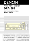
AUDIO VIDEO CONTROL RECEIVER
TX-DS656
Thank you for purchasing the Onkyo Audio Video
Control Receiver.
Please read this manual thoroughly before making
connections and turning on the power.
Following the instructions in this manual will enable
you to obtain optimum performance and listening
enjoyment from your new Audio Video Control
Receiver.
Please retain this manual for future reference.
Input source selection and surround
setup ................................................. 25
Listening to FM/AM broadcasts ........ 32
Receiving RDS broadcasts
(European models only) ................... 36
Using the Surround modes ................. 38
Recording from a source .................... 42
Using the TAPE-2 MONITOR
function ............................................ 44
Using the other remote controller functions
with the supplied remote controller ..... 45
Multi-room system connections......... 46
A few important notes
Troubleshooting ................................. 50
Specifications ..................................... 52
Control positions and names .............. 53
WARNING
TO REDUCE THE RISK OF FIRE OR ELECTRIC
SHOCK, DO NOT EXPOSE THIS APPLIANCE TO
RAIN OR MOISTURE.
CAUTION
TO REDUCE THE RISK OF ELECTRIC SHOCK, DO
NOT REMOVE COVER (OR BACK). NO USERSERVICEABLE PARTS INSIDE. REFER SERVICING
TO QUALIFIED SERVICE PERSONNEL.
WARNING
AVIS
RISK OF ELECTRIC SHOCK
DO NOT OPEN
RISQUE DE CHOC ELECTRIQUE
NE PAS OUVRIR
• The lightning flash with arrowhead symbol, within an
equilateral triangle, is intended to alert the user to the
presence of uninsulated "dangerous voltage" within the
product's enclosure that may be of sufficient magnitude
to constitute a risk of electric shock to persons.
• The exclamation point within an equilateral triangle is
intended to alert the user to the presence of important
operating and maintenance (servicing) instructions in
the literature accompanying the product.
Important Safeguards
1. Read Instructions – All the safety and operating instructions
should be read before the appliance is operated.
13.Cleaning – The appliance should be cleaned only as recommended
by the manufacturer.
2. Retain Instructions – The safety and operating instructions should
be retained for future reference.
14.Power Lines – An outdoor antenna should be located away from
power lines.
3. Heed Warnings – All warnings on the appliance and in the
operating instructions should be adhered to.
15.Nonuse Periods – The power cord of the appliance should be
unplugged from the outlet when left unused for a long period of
time.
4. Follow Instructions – All operating and use instructions should be
followed.
5. Water and Moisture – The appliance should not be used near
water - for example, near a bathtub, washbowl, kitchen sink,
laundry tub, in a wet basement, or near a swimming pool, and the
like.
6. Carts and Stands – The appliance should be used only with a cart
or stand that is recommended by the manufacturer.
6A.An appliance and cart combination
should be moved with care. Quick stops,
excessive force, and uneven surfaces
may cause the appliance and cart
combination to overturn.
PORTABLE CART
WARNING
16.Object and Liquid Entry – Care should be taken so that objects
do not fall and liquids are not spilled into the enclosure through
openings.
17.Damage Requiring Service – The appliance should be serviced by
qualified service personnel when:
A. The power-supply cord or the plug has been damaged; or
B. Objects have fallen, or liquid has been spilled into the
appliance; or
C. The appliance has been exposed to rain; or
D. The appliance does not appear to operate normally or exhibits a
marked change in performance; or
E. The appliance has been dropped, or the enclosure damaged.
S3125A
7. Wall or Ceiling Mounting – The appliance should be mounted to
a wall or ceiling only as recommended by the manufacturer.
8. Ventilation – The appliance should be situated so that its location
or position does not interfere with its proper ventilation. For
example, the appliance should not be situated on a bed, sofa, rug,
or similar surface that may block the ventilation openings; or if
placed in a built-in installation, such as a bookcase or cabinet that
may impede the flow of air through the ventilation openings, there
should be free space of at least 20 cm (8 in.) and an opening behind
the appliance.
9. Heat – The appliance should be situated away from heat sources
such as radiators, heat registers, stoves, or other appliances
(including amplifiers) that produce heat.
18.Servicing – The user should not attempt to service the appliance
beyond that described in the operating instructions. All other
servicing should be referred to qualified service personnel.
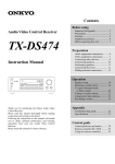
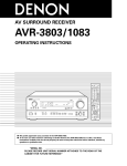
19.Outdoor Antenna Grounding - If an outside antenna is connected
to the receiver, be sure the antenna system is grounded so as to
provide some protection against voltage surges and built up static
charges. Article 810 of the National Electrical Code, ANSI/NFPA
70, provides information with regard to proper grounding of the
mast and supporting structure, grounding of the lead-in wire to an
antenna-discharge unit, size of grounding conductors, location of
antenna-discharge unit, connection to grounding electrodes, and
requirements for the grounding electrode. See Figure 1.
ANTENNA
LEAD IN
WIRE
10.Power Sources – The appliance should be connected to a power
supply only of the type described in the operating instructions or as
marked on the appliance.
11.Polarization – If the appliance is provided with a polarized plug
having one blade wider than the other, please read the following
information: The polarization of the plug is a safety feature. The
polarized plug will only fit the outlet one way. If the plug does not
fit fully into the outlet, try reversing it. If there is still trouble, the
user should seek the services of a qualified electrician. Under no
circumstances should the user attempt to defeat the polarization of
the plug.
12.Power-Cord Protection – Power-supply cords should be routed so
that they are not likely to be walked on or pinched by items placed
upon or against them, especially near plugs, convenience
receptacles, and the point where they exit from the appliance.
2
GROUND
CLAMP
ANTENNA
DISCHARGE UNIT
(NEC SECTION 810-20)
ELECTRIC
SERVICE
EQUIPMENT
GROUNDING CONDUCTORS
(NEC SECTION 810-21)
GROUND CLAMPS
POWER SERVICE GROUNDING
ELECTRODE SYSTEM
(NEC ART 250, PART H)
NEC – NATIONAL ELECTRICAL CODE
Precautions
1. Warranty Claim
You can find the serial number on the rear panel. In case of warranty
claim, please report this number.
2. Recording Copyright
Recording of copyrighted material for other than personal use is illegal
without permission of the copyright holder.
3. AC Fuse
The fuse is located inside the chassis and is not user-serviceable. If
power does not come on, contact your Onkyo authorized service
station.
4. Care
From time to time you should wipe off the front and rear panels and the
cabinet with a soft cloth. For heavier dirt, dampen a soft cloth in a weak
solution of mild detergent and water, wring it out dry, and wipe away
the dirt. Following this, dry immediately with a clean cloth. Do not use
rough material, thinners, alcohol or other chemical solvents or cloths
since these may damage the finish or remove the panel lettering.
5. Power
WARNING
BEFORE PLUGGING IN THE UNIT FOR THE FIRST TIME,
READ THE FOLLOWING SECTION CAREFULLY.
• The voltage of the available power supply differs according to
country or region. Be sure that the power supply voltage of the area
where this unit will be used meets the required voltage (e.g.,
AC230V 50Hz or AC120V 60Hz) written on the rear panel.
• Voltage Selector (Rear Panel)
Worldwide models are equipped with a voltage selector to conform
with local power supplies. Be sure to set this switch to match the
power supply in your area before plugging in the unit (see page 5).
Models without a voltage selector can only be used in areas where
the power supply voltage is the same as that of the unit.
FOR U.S. MODEL
Note to CATV System installer:
• This reminder is provided to call the CATV system installer's
attention to Section 820-40 of the NEC which provides guidelines
for proper grounding and, in particular, specifies that the cable
ground shall be connected to the grounding system of the building,
as close to the point cable entry as practical.
FCC Information for User
CAUTION:
Changes or modifications not expressly approved by the manufacturer for compliance could void the user's authority to operate the
equipment.
NOTE:
This equipment has been tested and found to comply with the limits
for a Class B digital device, pursuant to Part 15 of the FCC Rules.
These limits are designed to provide reasonable protection against
harmful interference in a residential installation. This equipment
generates, uses, and can radiate radio frequency energy and, if not
installed and used in accordance with the instructions, may cause
harmful interference to radio communications. However, there is no
guarantee that interference will not occur in a particular installation.
If this equipment does cause harmful interference to radio or
television reception, which can be determined by turning the
equipment off and on, the user is encouraged to try to correct the
interference by one or more of the following measures:
• Reorient or relocate the receiving antenna.
• Increase the separation between other equipment and the receiver.
• Connect the equipment into an outlet on a circuit different from
that to which the receiver is connected.
• Consult the dealer or an experienced radio/TV technician for help.
FOR CANADIAN MODEL:
(POUR LE MODELE CANADIEN)
• For models having a power cord with a polarized plug
CAUTION:TO PREVENT ELECTRIC SHOCK, MATCH WIDE
BLADE OF PLUG TO WIDE SLOT, FULLY INSERT.
THIS DIGITAL APPARATUS DOES NOT EXCEED THE CLASS B
LIMITS FOR RADIO NOISE EMISSION FROM DIGITAL APPARATUS
SET OUT IN THE RADIO INTERFERENCE REGULATIONS OF THE
CANADIAN DEPARTMENT OF COMMUNICATIONS.
• Sur les modèles dont la fiche est polarisée.
ATTENTION:POUR ÉVITER LES CHOCS ÉLECTRIQUES,
INTRODUIRE LA LAME LA PLUS LARGE DE LA FICHE DANS
LA BORNE CORRESPONDANTE DE LA PRISE ET POUSSER
JUSQ’AU FOND.
L'INTERFÉRENCE RADIO ÉLECTRIQUE GÉNÉRÉE PAR CET
APPAREIL NUMÉRIQUE DE TYPE B NE DÉPASSE PAS LES
LIMITES ÉNONCÉES DANS LE RÈGLEMENT SUR LES
PERTURBATIONS RADIO ÉLECTRIQUES, SECTION APPAREIL
NUMÉRIQUE, DU MINISTÈRE DES COMMUNICATIONS.
ATTENTION FOR BRITISH MODEL
Replacement and mounting of an AC plug on the power supply cord of
this unit should be performed only by qualified service personnel.
IMPORTANT
The wires in the mains lead are coloured in accordance with the
following code:
Blue:
Neutral
Brown:
Live
As the colours of the wires in the mains lead of this appliance may not
correspond with the coloured markings identifying the terminals in
your plug, proceed as follows:
The wire which is coloured BLUE must be connected to the terminal in
the plug which is marked with the letter N or coloured BLACK.
The wire which is coloured BROWN must be connected to the terminal
in the plug which is marked with the letter L or coloured RED.
IMPORTANT
A 5 amp fuse is fitted in this plug. Should the fuse need to be replaced,
please ensure that the replacement fuse has a rating of 5 amps and that
it is approved by ASTA or BSI to BS1362. Check for the ASTA mark
or the BSI mark on the body of the fuse.
IF THE FITTED MOULDED PLUG IS UNSUITABLE FOR THE
SOCKET OUTLET IN YOUR HOME, THEN THE FUSE SHOULD
BE REMOVED AND THE PLUG CUT OFF AND DISPOSED OF
SAFELY. THERE IS A DANGER OF SEVERE ELECTRICAL
SHOCK IF THE CUT OFF PLUG IS INSERTED INTO ANY 13
AMP SOCKET.
If in any doubt, please consult a qualified electrician.
FOR EUROPEAN MODEL
Declaration of Conformity
We, ONKYO EUROPE
ELECTRONICS GmbH
INDUSTRIESTRASSE 20
82110 GERMERING,
GERMANY
declare in own responsibility, that the ONKYO product described
in this instruction manual is in compliance with the corresponding
technical standards such as EN55013, EN55020, EN61000-3-2, -3-3
and EN60065
GERMERING, GERMANY
K.OTSU
ONKYO EUROPE ELECTRONICS GmbH
3
Features
Supplied accessories
Amplifier Features
■ 85 Watts Minimum of continuous RMS power to each of the five
channels into 8Ω from 20 Hz to 20 kHz with no more than 0.08%
THD (North American models, FTC rating)
European Models: 115 Watts minimum of continuous RMS power to
each of the five channels into 6Ω, 1,000Hz, DIN
Asian Models:
145 Watts minimum of continuous RMS power to
each of the five channels into 6Ω, 1 kHz, EIAJ
■ Powerful High-Current, Low-Impedance Drive Amplifiers for each
of the 5 channels, with discrete output stages–no inexpensive ICs–
assures that no channel information is compromised, and handles the
wide dynamics of 5.1 channel movie soundtracks cleanly and effortlessly
■ Low Negative Feedback, Wideband Circuitry minimizes noise
and distortion
■ High Resolution 20-Bit Delta Sigma D/A and A/D Converters
for greater precision
■ 3-D Bass lets you boost ultra-low frequencies to the front 3
channels, for bass with greater clarity and impact
AM loop antenna (1)
T-shaped FM antenna (1)
Remote controller (RC-373M) (1)
Batteries (size AA, R6, or UM-3) (2)
Audio/Video Features
■ Dolby* Digital® Processor Built-In to decode the 5.1 channel
pristine digital audio on DVDs, HDTV and other sources
■ 5.1 Channel External Inputs give you the option of connecting an
additional 5.1 channel decoder for DTS, MPEG and upcoming formats
■ Cinema Re-EQ™** Circuitry
■ 6 Surround Modes: Dolby Digital, Dolby Pro Logic, Hall, Live,
Arena and Studio, with user-adjustable parameters for each mode,
including venue size, effect and reverb levels, and reverb time delay
■ Upgraded Motorola 24-Bit Chip, the DSP56009, runs at 88 MHz, and
can execute 44 million instructions per second (MIPS) for greater
processing capacity that translates into better dynamics, more reflections
and more reverberations–parameters that define how real everything will
sound–also gives you more control over factors exclusive to your home
theaters, such as room size, ambiance, equalization and time delay
■ IPM–Intelligent Power Management for powering up entire system and
delivering surround sound whenever TV is turned on (audio triggered)
■ Onscreen Graphical Displays in 7 colors, with a Superimpose mode
to easily see the onscreen display over a TV picture–the display can
also be moved to different positions within the screen
■ NTSC/PAL Compatible (European and Asian models)
■ 6 Pre Out Jacks
Tuner Features
■
■
■
■
■
Rotary Smart Scan Controller
RDS (European models only) with PS, PTY, RT, TP
30 FM/AM Random Presets to store FM and AM stations
3 Station-Group Presets
Selectable Character-Display Input of up to 8 characters to write a
descriptive label for each of the 30 preset stations and 3 station-group
presets (A, B, C)
General Features
■ Multiroom/Multisource Capability with Main/Remote speaker
selector and outputs to play two different sources simultaneously
without the need of an additional amplifier (North American
models are compatible with Xantech® products)
■ 4-Mode Dimmer (bright, normal, low, off)
■ Audio Mute (remote) instantly switches off the sound–convenient
for phone calls, and for recording without listening
■ Sleep Timer (remote) shuts down system after 10 to 90 minutes
(10 min. steps)
■ Battery-Free Memory Backup protects memory's contents during
a power outage or it the unit is temporarily unplugged
* Manufactured under license from Dolby Laboratories.
"Dolby", "Pro Logic" and the double-D symbol are trademarks of Dolby
Laboratories. Confidential Unpublished Works. ©1992-1997 Dolby
Laboratories, Inc. All rights reserved.
** Re-Equalization™ is a trademark of Lucasfilm Ltd.
4
75/300 ohm antenna
adapter (1)
(Except for USA and
European models)
Conversion plug (1)
(Worldwide model only)
Multi-Room Remote System (MRX)
By connecting the Multi-Room Remote System equipment, you can
operate all components connected to the TX-DS656 from either the
main room or the sub-room. (Refer to pages 46 to 48 for more details.)
The following equipment (sold separately) is essential for using the
Onkyo Multi-Room System:
U.S. & Canada:
• Onkyo's Multi-Room System kits HKT-600 or HKT-700 (IR
Remote Control Extension System) and
• Xantech's Multi-Room System
Other areas:
• Sensor Unit: Model No. HR-10
• Remote Emitter: Model No. HE-50 (AC)
• Remote Emitter Head: Model No. HE-10
The following secondary remote controller can be used to operate
the system from the sub-room:
• Secondary Remote Controller for Multi-Room Remote System:
Model No. RC-MR1H
Consult your nearest Onkyo service center when replacing your
Onkyo Multi-Room System with a Xantech Multi-Room System.
Memory Preservation
This unit does not require memory preservation batteries. A built-in
memory power back-up system preserves the contents of the
memory during power failures and even when the unit is unplugged.
The unit must be plugged in order to charge the back-up system.
The memory preservation period after the unit has been unplugged
varies depending on climate and placement of the unit. On the
average, memory contents are protected over a period of a few
weeks after the last time the unit has been unplugged. This period is
shorter when the unit is exposed to a highly humid climate.
Before using this unit
Setting the AM tuning step frequency
(worldwide model only)
AM FREQUENCY
STEP
Worldwide models are equipped with a switch that controls the AM
band tuning steps. Set this switch to match the AM band tuning step
frequency in your area.
U.S.A. and Canada : 10kHz
Other areas
: 9kHz
10kHz
9kHz
MJ
27122482
Setting the voltage selector
(worldwide model only)
VOLTAGE SELECTOR
220-230V
120V
Worldwide models are equipped with a voltage selector to conform
with local power supplies. Be sure to set this switch to match the
voltage of the power supply in your area before plugging in the unit.
1. Determine the proper voltage for your area: 220-230V or 120V.
2. If the preset voltage is not correct for your area, insert a screwdriver
into the groove in the switch. Slide the switch all the way to the
right (120V) or to the left (220-230V), whichever is appropriate.
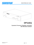
Installing the batteries
+
+
1. Remove the battery compartment cover by pressing and sliding it
out.
2. Insert two AA (R6 or UM-3)-size batteries into the battery
compartment. Carefully follow the polarity diagram (positive (+)
and negative (-) symbols) inside the battery compartment.
3. After batteries are installed and seated correctly, replace the
compartment cover.
• If the battery voltage is low, the indicator on the remote controller
does not flash when you press a button on the controller.
Remove low-voltage batteries immediately to avoid damage due to
corrosion. Never mix old and new batteries.
• The learned codes are retained, even when the batteries are
replaced.
They may be lost, however, if battery replacement is not completed
within one hour. In this case, the unit must learn the codes again.
• The manganese batteries supplied with this unit have a service life
of approximately six months, depending on the frequency of use.
• Use spare batteries of the type specified in the table below.
+
-
-
Type
Voltage
Size
Manganese or
Alkaline
1.5V
AA, R6 (UM-3) or
LR6 (AM-3)
We recommend that long-life AA (LR6 or AM-3)-size alkaline
batteries be used.
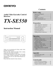
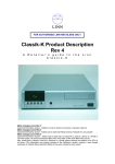
Using the remote controller
TX-DS656
Remote control sensor
STAND-BY
indicator
30˚
30˚
approx. 5m (16 feet)
The STAND-BY indicator lights up when the unit receives a signal
from the remote controller.
The following information will help you get optimal use from the
remote controller.
• Place this receiver away from direct bright light, which could
prevent proper operation of the remote controller.
• Make sure audio rack doors do not have tinted glass. Placing the
receiver behind such a door may prevent proper remote control.
• Using other remote controllers along with this receiver's remote
controller in the same room may cause interference.
RC-373M
5
Connection
This section describes, step by step, how to connect the TX-DS656 to
your home theater components.
1
2
3
4
5
6
7
8
9
0
A
B
C
D
Connecting analog audio source equipment
Connecting digital audio source equipment
Connecting video source equipment
Connecting a video camera or TV game machine
Connecting a decoder with 5.1-channel output
Connecting video recording equipment
Connecting audio recording equipment
Connecting the z remote control cables
Connecting a TV/monitor
Connecting the antennas
Connecting speakers
Connecting power amplifiers
Using the AC outlets
Connecting the power
page 8
page 8
page 9
page 9
page 10
page 10
page 11
page 11
page 12
page 13
page 15
Page 16
Page 17
Page 17
To connect source or recording equipment, use cables supplied by the
equipment manufacturer.
Note:
• Do not turn on any component until you have completed all
connections.
• Insert the plugs and connectors completely. Remember that
improper connection may result in noise or malfunction.
• Do not bind audio connection cables with power cords and speaker
cables. Doing so may degrade sound quality.
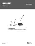
Improper connection
0 Connecting the antennas
AM loop antenna
0 Connecting the antennas
T-shaped FM antenna
1 Connecting analog audio source equipment
CD player
Insert the plugs and connectors
securely. Remember that improper
connection can result in noise,
poor performance, or damage to
the equipment.
Insert completely.
1 Connecting analog audio source equipment
Turntable
1 Connecting analog audio source equipment
7 Connecting audio recording equipment
MD recorder, DAT deck, or cassette tape deck
/
6
3 Connecting video source
equipment
6 Connecting video recording
equipment
2 Connecting digital audio source
equipment
CD player, DAT deck or MD recorder
Video cassette recorder
5 Connecting a decoder with 5.1-channel
output
Decoder with 5.1-ch output
3 Connecting video source
equipment
DVD player
A Connecting speakers
MJ
L
R
V
IN
R
L
R
L
SURROUND
OUT
VIDEO-2
CENTER
DVD
L
MONITOR
OUTPUT
V
(REC)
R
OUT
R
CAUTION: SPEAKER IMPEDANCE
6 OHMS MIN. / SPEAKER
R
FRONT REMOTE SPEAKERS
D Connecting the Power
L
AC 120V 60Hz
SWITCHED
TOTAL 120W 1A MAX.
REMOTE CONTROL
OUT
IN
IN
TAPE-2
R
CENTER SUBWOOFER
L
L
AC OUTLETS
(PLAY)
PHONO
R
L
L
R
DIGITAL 3
(COAXIAL)
SURROUND
OUT
R
L
(REC)
GND
L
SUBWOOFER
DIGITAL 2
(COAXIAL)
S
FRONT
IN
CD
R
DIGITAL 1
(OPTICAL)
IN
FM
300
TAPE-1
SPEAKERS
MULTI
CHANNEL
INPUT
DIGITAL INPUT
(PLAY)
FRONT MAIN
IN
IN
FM
75
IN
CENTER
SPEAKER
FRONT
IN
OUT
AM
SURROUND SPEAKERS
OUT
VIDEO-1
ANTENNA
27122482
S
OUT
PRE OUT
WARNING
AVIS
RISK OF ELECTRIC SHOCK
DO NOT OPEN
RISQUE DE CHOC ELECTRIQUE
NE PAS OUVRIR
8 Connecting the z remote C Using the AC outlets
control cables
9 Connecting a TV/monitor
TV
4 Connecting a video camera or TV game machine
VIDEO-3/VIDEO CAM INPUT
AV DIGITAL SURROUND AMPLIFIER
MASTER VOLUME
SMART SCAN CONTROLLER
PRESET
POWER
TUNING
SURROUND
ENTER
PARAMETER
STAND-BY
SPEAKERS
MAIN
REMOTE
3-D BASS
REC OUT
DIGITAL AUDIO
SELECTOR
MULTI SOURCE
MULTI CH INPUT
PTY/TP
MIDNIGHT
THEATER
Re-EQ
DISPLAY CHARACTER AUTO TUN
SCAN
GROUP
MIN
MAX
BASS
TREBLE
MEMORY FM MUTE / MODE
CLEAR
VIDEO 3 / VIDEO CAM INPUT
PHONES
DVD
S VIDEO
VIDEO
L AUDIO R(MONO)
VIDEO-1
VCR-1
VIDEO-2
VCR-2 / TV
VIDEO-3
CAM
TAPE-1
MD
TAPE-2
MONITOR
FM
AM
PHONO
CD
A-DS656
B Connecting power amplifiers
7
Connection
1 Connecting analog audio source equipment
CD player
Connect your audio source equipment, such as a turntable, CD player,
MD recorder, DAT deck, or cassette tape deck, as shown below.
Audio connection cable
OUT
MJ
L
R
V
SURROUND SPEAKERS
OUT
SURROUND
IN
L
R
OUT
CENTER
SPEAKER
FRONT MAIN
SPEAKERS
FRONT
L
R
IN
(White)
(Red)
27122482
S
OUT
VIDEO-1
ANTENNA
R
L
R
L
R
L
MULTI
CHANNEL
OUT
INPUT
VIDEO-2
AM
CENTER
CAUTION: SPEAKER IMPEDANCE
SUBWOOFER
6 OHMS MIN. / SPEAKER
IN
IN
DIGITAL INPUT
FM
75
IN
DVD
DIGITAL 1
IN
FM
300
(OPTICAL)
V
(REC)
R
L
MONITOR
DIGITAL 2
OUTPUT
(COAXIAL)
OUT
TAPE-1
S
(PLAY)
R
(COAXIAL)
L
(REC)
AC OUTLETS
AC 120V 60Hz
SURROUND
OUT
R
REMOTE CONTROL
L
SWITCHED
IN
OUT
TAPE-2
R
CENTER SUBWOOFER
PRE OUT
L
To source's Right
output jack
TOTAL 120W 1A MAX.
IN
(PLAY)
PHONO
R
L
(White)
(Red)
FRONT REMOTE SPEAKERS
DIGITAL 3
FRONT
IN
CD
GND
To receiver's TAPE-1/
TAPE-2 L IN (PLAY)
To source's Left
output jack
TX-DS656
WARNING
AVIS
RISK OF ELECTRIC SHOCK
DO NOT OPEN
RISQUE DE CHOC ELECTRIQUE
NE PAS OUVRIR
To receiver's TAPE-1/
TAPE-2 R IN (PLAY)
(REC)
OUT
TAPE-1
R
L
(PLAY)
If you have a 3-head cassette tape deck...
Connect it to the TAPE-2 IN jacks. This allows you to monitor the
sound being recorded.
IN
CD
(REC)
OUT
GND
IN
GND terminals
Connect the grounding wire of your turntable to one of these terminals.
Use the other terminal as a spare. Do not leave the grounding wire
connected if noise increases after connecting.
(PLAY)
PHONO
R
L
TAPE-2
L
R
: Signal flow
OUT
OUT
IN
/
MD recorder, DAT deck, or
cassette tape deck
Turntable
2 Connecting digital audio source equipment
The TX-DS656 has three digital input terminals. Therefore, you can
connect up to three digital audio sources, such as a CD player, MD
recorder, or DAT deck, etc., using optical and coaxial cables.
Note:
Even if the digital source is connected via optical or coaxial cable, it
also must be connected via audio connection cables. The TX-DS656
receives analog signals from input source equipment only during
recording or when the Multi-source function is enabled.
DIGITAL INPUT
DIGITAL 1
(OPTICAL)
• Source with optical digital output
TX-DS656
DIGITAL 2
(COAXIAL)
MJ
L
R
V
SURROUND SPEAKERS
OUT
SURROUND
IN
L
R
OUT
FRONT MAIN
Optical cable
SPEAKERS
L
R
IN
CENTER
SPEAKER
FRONT
VIDEO-1
ANTENNA
27122482
S
OUT
R
L
R
L
R
L
MULTI
CHANNEL
OUT
INPUT
VIDEO-2
AM
CENTER
6 OHMS MIN. / SPEAKER
DIGITAL INPUT
IN
DVD
To receiver's DIGITAL
INPUT DIGITAL 1
(OPTICAL) terminal
DIGITAL 1
IN
FM
300
(OPTICAL)
L
DIGITAL 2
OUTPUT
OUT
TAPE-1
R
MONITOR
V
(REC)
DIGITAL 3
(COAXIAL)
CAUTION: SPEAKER IMPEDANCE
SUBWOOFER
IN
IN
FM
75
DIGITAL 3
FRONT
IN
R
(COAXIAL)
L
(REC)
AC OUTLETS
AC 120V 60Hz
SURROUND
OUT
R
FRONT REMOTE SPEAKERS
(COAXIAL)
S
(PLAY)
CD
GND
L
REMOTE CONTROL
OUT
SWITCHED
IN
TOTAL 120W 1A MAX.
IN
(PLAY)
PHONO
R
L
TAPE-2
R
CENTER SUBWOOFER
L
PRE OUT
WARNING
AVIS
RISK OF ELECTRIC SHOCK
DO NOT OPEN
RISQUE DE CHOC ELECTRIQUE
NE PAS OUVRIR
To source's optical
output terminal
• Source with coaxial digital output
Optical
output
Coaxial output
Coaxial cable
: Signal flow
To source's coaxial
output terminal
CD player, DAT deck or
MD recorder
8
To receiver's DIGITAL
INPUT DIGITAL 2
(COAXIAL) or DIGITAL
3 (COAXIAL) terminal
Note:
• Remove the protective cap covering the DIGITAL-1 (OPTICAL)
terminal before trying to make a connection. When this terminal is
not in use, replace the protective cap.
• If you have an LD player with AC-3RF output, connect it via an
AC-3RF demodulator to one of the TX-DS656's DIGITAL INPUT
terminals.
Connection
3 Connecting video source equipment
• With a DVD player, video disc player, etc., that is equipped with at least
one digital audio output terminal, its audio output can be connected to the
TX-DS656 via an optical or coaxial cable (see the previous page). In this
case, for recording or using the Multi-source function, it is also necessary
that you connect the equipment via audio connection cables.
• The VIDEO-1 and VIDEO-2 OUT jacks can be used to connect
recording equipment such as a video cassette recorder.
• Video input signals to the TX-DS656 cannot be output back to the same or
other equipment. In other words, the VIDEO-1 V OUT jack does not output
signals which have been input to the TX-DS656 from its VIDEO-1 V IN jack.
TX-DS656
MJ
L
R
V
27122482
S
OUT
SURROUND SPEAKERS
OUT
IN
SURROUND
IN
L
R
OUT
CENTER
SPEAKER
FRONT MAIN
SPEAKERS
FRONT
L
R
VIDEO-1
ANTENNA
R
L
R
L
R
L
MULTI
CHANNEL
OUT
INPUT
VIDEO-2
AM
CENTER
CAUTION: SPEAKER IMPEDANCE
SUBWOOFER
6 OHMS MIN. / SPEAKER
IN
IN
DIGITAL INPUT
FM
75
IN
DVD
DIGITAL 1
IN
FM
300
(OPTICAL)
L
DIGITAL 2
OUTPUT
OUT
TAPE-1
R
MONITOR
V
(REC)
R
CD
DIGITAL 3
FRONT
IN
(COAXIAL)
L
(REC)
AC OUTLETS
AC 120V 60Hz
SURROUND
OUT
GND
R
FRONT REMOTE SPEAKERS
(COAXIAL)
S
(PLAY)
L
REMOTE CONTROL
SWITCHED
IN
OUT
TOTAL 120W 1A MAX.
IN
(PLAY)
PHONO
R
L
R
L
TAPE-2
CENTER SUBWOOFER
PRE OUT
L
R
V
WARNING
AVIS
RISK OF ELECTRIC SHOCK
DO NOT OPEN
RISQUE DE CHOC ELECTRIQUE
NE PAS OUVRIR
S-Video connection cable
S
OUT
OUT
FRONT
VIDEO-1
IN
L
R
L
OUT
SURROUND
OUT
VIDEO-2
CENTER
MULTI
CHANNEL
INPUT
To source's S-Video
output jack
Video connection cable
SUBWOOFER
DVD
To source's Video
output jack
IN
To source's Left
audio output jack
(White)
(Red)
IN
To receiver's VIDEO1/2/3/DVD S IN jack
IN
IN
IN
R
IN
OUT
OUT
To source's Right
audio output jack
(Yellow)
(Yellow)
Audio connection cable
To receiver's VIDEO1/2/3/DVD V IN jack
To receiver's VIDEO1/2/3/DVD L IN jack
(White)
(Red)
To receiver's VIDEO1/2/3/DVD R IN jack
If you have connected a video source with an S-Video output
Video cassette recorder
DVD player
• The TX-DS656 does not convert S-video input signals into normal
video signals. That is, input signals to the VIDEO-1/2/3/DVD S IN
jack will be output from the MONITOR OUTPUT S jack and the
VIDEO-1/2 S OUT jack only. Similarly, input signals to the VIDEO1/2/3/DVD V IN jack will be output from the MONITOR OUTPUT V
jack and the VIDEO-1/2 V OUT jack only.
• See the owner's manual of your video source equipment to determine
whether to connect it via normal video connection cables only or via
both normal video and S-video connection cables.
: Signal flow
4 Connecting a video camera or TV game machine
TX-DS656
AV DIGITAL SURROUND AMPLIFIER
MASTER VOLUME
SMART SCAN CONTROLLER
PRESET
POWER
TUNING
SURROUND
ENTER
PARAMETER
STAND-BY
PTY/TP
SPEAKERS
MAIN
REMOTE
3-D BASS
REC OUT
DIGITAL AUDIO
SELECTOR
MULTI SOURCE
MULTI CH INPUT
PTY/TP
MIDNIGHT
THEATER
Re-EQ
DISPLAY CHARACTER AUTO TUN
SCAN
GROUP
MIN
MAX
BASS
TREBLE
MEMORY FM MUTE / MODE
CLEAR
VIDEO 3 / VIDEO CAM INPUT
PHONES
DVD
S VIDEO
VIDEO
VIDEO-1
VCR-1
VIDEO-2
VCR-2 / TV
VIDEO-3
CAM
TAPE-1
MD
TAPE-2
MONITOR
FM
AM
PHONO
CD
L AUDIO R(MONO)
A-DS656
Connect your video camera or TV game machine to the VIDEO-3/
VIDEO CAM INPUT jacks.
If a monaural video camera is used, connect its audio connection cable
to "R (MONO)" audio jack.
VIDEO 3 / VIDEO CAM INPUT
S VIDEO
VIDEO
L AUDIO R (MONO)
: Signal flow
OUT
Video camera or TV game machine
9
Connection
5 Connecting a decoder with 5.1-channel output
TX-DS656
MJ
L
R
V
27122482
S
OUT
IN
FRONT MAIN
SPEAKER
SPEAKERS
FRONT
R
L
R
L
SURROUND
IN
OUT
CENTER
SURROUND SPEAKERS
OUT
VIDEO-1
ANTENNA
R
L
R
L
R
The TX-DS656's MULTI CHANNEL INPUT jacks can be used to
connect a decoder equipped with 5.1-ch audio output (dts decoder,
MPEG decoder, etc.). If you do so, use the V or S IN jack of the
VIDEO-1/2/3 or DVD connector to connect the video or S-video
connection cable.
L
MULTI
CHANNEL
OUT
INPUT
VIDEO-2
AM
CENTER
CAUTION: SPEAKER IMPEDANCE
SUBWOOFER
6 OHMS MIN. / SPEAKER
IN
IN
DIGITAL INPUT
FM
75
IN
DVD
DIGITAL 1
IN
FM
300
(OPTICAL)
DIGITAL 2
OUTPUT
OUT
TAPE-1
L
MONITOR
V
(REC)
R
DIGITAL 3
FRONT
IN
R
L
R
L
(REC)
(COAXIAL)
AC OUTLETS
AC 120V 60Hz
SURROUND
OUT
FRONT REMOTE SPEAKERS
(COAXIAL)
S
(PLAY)
CD
GND
REMOTE CONTROL
OUT
SWITCHED
IN
TOTAL 120W 1A MAX.
IN
(PLAY)
PHONO
R
L
R
L
TAPE-2
R
CENTER SUBWOOFER
L
PRE OUT
V
WARNING
AVIS
RISK OF ELECTRIC SHOCK
DO NOT OPEN
RISQUE DE CHOC ELECTRIQUE
NE PAS OUVRIR
S
OUT
OUT
FRONT
VIDEO-1
IN
L
R
L
IN
OUT
SURROUND
CENTER
SUBWOOFER
DVD
To receiver's MULTI
CHANNEL INPUT L
(White)
FRONT jack
(Red)
IN
IN
Audio connection cable
To decoder's
multi-channel output
(White)
Left front jack
MULTI
CHANNEL
INPUT
OUT
VIDEO-2
IN
R
(Red)
To decoder's
multi-channel output
Right front jack
IN
To receiver's MULTI
CHANNEL INPUT R
FRONT jack
Audio connection cable
To decoder's multichannel output Left
surround jack (White)
To receiver's MULTI
CHANNEL INPUT L
(White)
SURROUND jack
(Red)
OUT
(Red)
To decoder's multichannel output Right
surround jack
OUT
: Signal flow
To receiver's MULTI
CHANNEL INPUT R
SURROUND jack
Monaural audio cable
Decoder with 5.1-ch output
To receiver's MULTI
CHANNEL INPUT
SUBWOOFER jack
To decoder's
multi-channel output
Subwoofer jack
Monaural audio cable
To receiver's MULTI
CHANNEL INPUT
CENTER jack
To decoder's
multi-channel output
Center jack
Note:
The Surround function cannot be used if audio signals are input from
the MULTI CHANNEL INPUT connector.
6 Connecting video recording equipment
TX-DS656
MJ
L
R
V
OUT
SURROUND SPEAKERS
OUT
IN
FRONT MAIN
SPEAKERS
FRONT
SURROUND
IN
L
R
OUT
CENTER
SPEAKER
L
R
VIDEO-1
ANTENNA
27122482
S
R
L
R
L
R
L
MULTI
CHANNEL
OUT
INPUT
VIDEO-2
AM
CENTER
CAUTION: SPEAKER IMPEDANCE
SUBWOOFER
DIGITAL INPUT
IN
Connect your video cassette recorder to the VIDEO-1/VIDEO-2 OUT jacks.
6 OHMS MIN. / SPEAKER
IN
IN
FM
75
DVD
DIGITAL 1
IN
FM
300
(OPTICAL)
DIGITAL 2
OUTPUT
OUT
TAPE-1
L
MONITOR
V
(REC)
R
R
L
R
L
(REC)
(COAXIAL)
AC OUTLETS
AC 120V 60Hz
SURROUND
OUT
GND
REMOTE CONTROL
OUT
SWITCHED
IN
TOTAL 120W 1A MAX.
IN
(PLAY)
PHONO
R
L
TAPE-2
R
CENTER SUBWOOFER
L
S-Video connection cable
DIGITAL 3
FRONT
IN
FRONT REMOTE SPEAKERS
(COAXIAL)
S
(PLAY)
CD
PRE OUT
WARNING
AVIS
RISK OF ELECTRIC SHOCK
DO NOT OPEN
RISQUE DE CHOC ELECTRIQUE
NE PAS OUVRIR
To source's S-Video
input jack
R
L
V
OUT
To receiver's VIDEO1/2 S OUT jack
S
Video connection cable
OUT
VIDEO-1
IN
IN
OUT
OUT
To source's Video
input jack
(Yellow)
(Yellow)
To receiver's VIDEO1/2 V OUT jack
VIDEO-2
IN
IN
IN
DVD
IN
To source's Left
audio input jack
(White)
(Red)
To source's Right
audio input jack
IN
OUT
Video cassette recorder
: Signal flow
10
Audio connection cable
To receiver's VIDEO1/2 L OUT jack
(White)
(Red)
To receiver's VIDEO1/2 R OUT jack
Note:
When you connect a VCR, etc. to the VIDEO-2 R/L jacks, you must
turn the IPM function off. (See page 12.)
Connection
7 Connecting audio recording equipment
TX-DS656
MJ
L
R
V
FRONT MAIN
SPEAKER
SPEAKERS
FRONT
L
R
SURROUND
IN
L
R
OUT
CENTER
SURROUND SPEAKERS
OUT
IN
Connect your audio recording equipment to the TAPE-1/2 OUT (REC)
jacks.
Digital recording is not possible, even if a DAT deck or MD recorder is
connected.
27122482
S
OUT
VIDEO-1
ANTENNA
R
L
R
L
R
L
MULTI
CHANNEL
OUT
INPUT
VIDEO-2
AM
CENTER
CAUTION: SPEAKER IMPEDANCE
SUBWOOFER
6 OHMS MIN. / SPEAKER
IN
IN
DIGITAL INPUT
FM
75
IN
DVD
DIGITAL 1
IN
FM
300
(OPTICAL)
DIGITAL 2
OUTPUT
OUT
TAPE-1
L
MONITOR
V
(REC)
R
DIGITAL 3
FRONT
IN
R
(COAXIAL)
L
(REC)
AC OUTLETS
AC 120V 60Hz
SURROUND
OUT
R
FRONT REMOTE SPEAKERS
(COAXIAL)
S
(PLAY)
CD
GND
L
REMOTE CONTROL
OUT
SWITCHED
IN
TOTAL 120W 1A MAX.
IN
(PLAY)
PHONO
R
L
TAPE-2
R
CENTER SUBWOOFER
PRE OUT
L
WARNING
AVIS
RISK OF ELECTRIC SHOCK
DO NOT OPEN
RISQUE DE CHOC ELECTRIQUE
NE PAS OUVRIR
To source's Left
audio input jack
(REC)
OUT
TAPE-1
(PLAY)
Audio connection cable
(White)
(Red)
IN
To source's Right
audio input jack
(REC)
OUT
To receiver's TAPE1/2 OUT (REC)
(White)
(Red)
To receiver's TAPE1/2 OUT (REC)
IN
(PLAY)
TAPE-2
L
R
OUT
IN
: Signal flow
If you have a 3-head cassette tape deck
Connect it to the TAPE-2 IN jacks. This allows you to monitor the
sound being recorded.
/
MD recorder, DAT or cassette tape deck
If you have a graphic equalizer
TX-DS656
MJ
L
R
V
SURROUND SPEAKERS
OUT
SURROUND
IN
L
R
OUT
CENTER
SPEAKER
FRONT MAIN
SPEAKERS
FRONT
L
R
IN
Connect the graphic equalizer to the TAPE-2 IN jacks and the recorder to
the equalizer. If you do so, you can use the TAPE-2 Monitor function to
monitor the sound processed by the equalizer during recording.
27122482
S
OUT
VIDEO-1
ANTENNA
R
L
R
L
R
L
MULTI
CHANNEL
OUT
INPUT
VIDEO-2
AM
CENTER
CAUTION: SPEAKER IMPEDANCE
SUBWOOFER
6 OHMS MIN. / SPEAKER
IN
IN
DIGITAL INPUT
FM
75
IN
DVD
: Signal flow
DIGITAL 1
IN
FM
300
(OPTICAL)
V
(REC)
L
DIGITAL 2
OUTPUT
OUT
TAPE-1
R
MONITOR
DIGITAL 3
FRONT
IN
R
(COAXIAL)
L
(REC)
AC OUTLETS
AC 120V 60Hz
SURROUND
OUT
R
FRONT REMOTE SPEAKERS
(COAXIAL)
S
(PLAY)
CD
GND
L
REMOTE CONTROL
OUT
SWITCHED
IN
TOTAL 120W 1A MAX.
IN
(PLAY)
PHONO
R
L
TAPE-2
R
CENTER SUBWOOFER
L
PRE OUT
WARNING
AVIS
RISK OF ELECTRIC SHOCK
DO NOT OPEN
RISQUE DE CHOC ELECTRIQUE
NE PAS OUVRIR
CAUTION:
Do not select a Surround mode when using the equalizer. This will result
in distortion and possible damage to the Surround decoder circuitry.
(REC)
OUT
TAPE-1
(PLAY)
Graphic equalizer
IN
(REC)
OUT
OUT
IN
IN
(PLAY)
TAPE-2
R
L
/
MJ
L
R
V
27122482
S
OUT
SURROUND SPEAKERS
OUT
IN
SURROUND
IN
L
R
OUT
CENTER
SPEAKER
FRONT MAIN
SPEAKERS
8 Connecting the z remote control cables
FRONT
L
R
VIDEO-1
ANTENNA
R
L
R
L
R
L
MULTI
CHANNEL
OUT
INPUT
VIDEO-2
AM
CENTER
DVD
DIGITAL 1
IN
(OPTICAL)
V
(REC)
TAPE-1
R
L
MONITOR
DIGITAL 2
OUTPUT
(COAXIAL)
OUT
S
(PLAY)
R
(COAXIAL)
L
(REC)
AC OUTLETS
AC 120V 60Hz
SURROUND
OUT
R
FRONT REMOTE SPEAKERS
DIGITAL 3
FRONT
IN
CD
GND
L
REMOTE CONTROL
OUT
SWITCHED
IN
TOTAL 120W 1A MAX.
IN
(PLAY)
PHONO
R
L
TAPE-2
R
CENTER SUBWOOFER
L
PRE OUT
REMOTE CONTROL
Cassette tape
deck
6 OHMS MIN. / SPEAKER
DIGITAL INPUT
IN
FM
300
CD player
CAUTION: SPEAKER IMPEDANCE
SUBWOOFER
IN
IN
FM
75
WARNING
AVIS
RISK OF ELECTRIC SHOCK
DO NOT OPEN
RISQUE DE CHOC ELECTRIQUE
NE PAS OUVRIR
An Onkyo cassette tape deck, CD player or DVD player equipped with
an z jack can be connected to the TX-DS656 via the remote control
cable supplied with the unit. Once connected, it can be operated by
using the receiver's remote controller.
Note:
• Connect the remote control cable to the black jack with the z
mark.
mark; never connect it to the jack with the
• For playback and recording, the unit also must be connected via
audio connection cables.
• Do not use the z REMOTE CONTROL jack to connect products
not bearing z symbol. Doing so may result in the failure of the
equipment.
• You cannot operate turntables and MD recorders by remote controller
even if they are Onkyo z compatible.
DVD player
11
Connection
9 Connecting a TV/monitor
TX-DS656
MJ
L
R
V
ANTENNA
SURROUND
IN
L
R
OUT
SPEAKER
FRONT MAIN
SPEAKERS
FRONT
L
R
IN
CENTER
SURROUND SPEAKERS
OUT
A TV or monitor equipped with a video input jack can be connected to
the TX-DS656.
27122482
S
OUT
VIDEO-1
R
L
R
L
R
L
MULTI
CHANNEL
OUT
INPUT
VIDEO-2
AM
CENTER
CAUTION: SPEAKER IMPEDANCE
SUBWOOFER
6 OHMS MIN. / SPEAKER
IN
IN
DIGITAL INPUT
FM
75
IN
DVD
DIGITAL 1
IN
FM
300
(OPTICAL)
DIGITAL 2
OUTPUT
OUT
TAPE-1
L
MONITOR
V
(REC)
R
DIGITAL 3
FRONT
IN
R
(COAXIAL)
L
(REC)
AC OUTLETS
AC 120V 60Hz
SURROUND
OUT
GND
R
FRONT REMOTE SPEAKERS
(COAXIAL)
S
(PLAY)
CD
L
REMOTE CONTROL
OUT
SWITCHED
IN
TOTAL 120W 1A MAX.
IN
(PLAY)
PHONO
R
L
TAPE-2
R
CENTER SUBWOOFER
PRE OUT
L
WARNING
AVIS
RISK OF ELECTRIC SHOCK
DO NOT OPEN
RISQUE DE CHOC ELECTRIQUE
NE PAS OUVRIR
S-Video connection cable
V
To TV's S-Video
input jack
MONITOR
OUTPUT
To receiver's MONITOR
OUTPUT S jack
Video connection cable
S
To TV's Video input (Yellow)
jack
(Yellow)
To receiver's MONITOR
OUTPUT V jack
: Signal flow
IN
Note:
If distortion of the TV image occurs or if noise is output from the unit,
place the unit and the TV as far apart as possible.
TV
Turning the unit on/off with the TV's power switch – IPM function
1
The TX-DS656 is equipped with the IPM (Intelligent Power Management) system.
Just turn on your TV's power switch and, in about 5 seconds, the TXDS656 turns on automatically. If you turn off the TV's power switch,
"." flashes on the display and the TX-DS656 automatically turns off in
about 5 minutes.
TX-DS656
TV
MJ
L
R
V
27122482
S
OUT
SURROUND SPEAKERS
OUT
IN
R
L
R
L
SURROUND
IN
OUT
CENTER
SPEAKER
FRONT MAIN
SPEAKERS
FRONT
VIDEO-1
ANTENNA
R
L
R
L
R
L
MULTI
CHANNEL
OUT
INPUT
VIDEO-2
AM
CENTER
6 OHMS MIN. / SPEAKER
DIGITAL INPUT
DVD
IN
DIGITAL 1
IN
FM
300
(OPTICAL)
DIGITAL 2
OUTPUT
OUT
TAPE-1
L
MONITOR
V
(REC)
R
DIGITAL 3
FRONT
IN
R
(COAXIAL)
L
(REC)
AC OUTLETS
AC 120V 60Hz
SURROUND
OUT
R
FRONT REMOTE SPEAKERS
(COAXIAL)
S
(PLAY)
CD
L
REMOTE CONTROL
OUT
SWITCHED
IN
TOTAL 120W 1A MAX.
IN
(PLAY)
PHONO
R
L
R
CAUTION: SPEAKER IMPEDANCE
SUBWOOFER
IN
IN
FM
75
GND
TAPE-2
R
CENTER SUBWOOFER
L
PRE OUT
L
WARNING
AVIS
RISK OF ELECTRIC SHOCK
DO NOT OPEN
RISQUE DE CHOC ELECTRIQUE
NE PAS OUVRIR
V
OUT
S
OUT
VIDEO-1
IN
IN
OUT
To activate the IPM function...
1. Connect the audio output of your TV to the TX-DS656's
VIDEO-2 L and R IN jacks.
If a monaural TV is used, connect the TV's audio output to the TXDS656's VIDEO-2 L IN jack.
2. Press the VIDEO-2 VCR-2/TV button on the front panel.
"VIDEO-2 VCR" or "VIDEO-2 TV" appears on the display.
3. Press the VIDEO-2 VCR/TV button repeatedly until "IPM
OFF (or IPM ON, if the function is already activated)" appears
on the display.
4. Rotate the SMART SCAN CONTROLLER to select "IPM ON".
• The IPM function is activated and, after 3 seconds, the display
changes to "VIDEO-2 TV".
• If you select "IPM OFF", the display will change to "VIDEO-2
VCR" after 3 seconds.
IN
OUT
OUT
VIDEO-2
IN
IN
IN
V
: Signal flow
DVD
IN
MONITOR
OUTPUT
S
3
VIDEO-2
VCR-2 / TV
IPM
4
SMART SCAN CONTROLLER
IPM
12
Note:
• The IPM system may not function properly with some TV sets.
• When the IPM system is activated, the video input signals to the
VIDEO-2 V IN jack are not output from the MONITOR OUTPUT
V jack.
• Setting a digital input mode for the VIDEO-2 input source automatically turns off the IPM function. You cannot turn on the TXDS656 automatically.
• The IPM function cannot be used when the MULTI-CH INPUT
source is selected.
CAUTION:
If you have connected the TV's video output and video input to the TXDS656's VIDEO-2 V IN and MONITOR OUTPUT V jacks, be sure to
turn ON the IPM function. Otherwise, the signals will loop in the
circuit, causing damage to the unit.
Connection
Indoor
antenna
Outdoor
antenna
300 ohms
ribbon wire
1
2
Connecting the antenna cable to the 75/300 ohm
antenna adapter (worldwide models)
Connecting a 300 ohm ribbon wire to the 75/300 ohm adapter:
Loosen the screws and wrap the wire around them. Tighten the screws
with a screwdriver.
3
✦
✦ ✦ ✦ ✦
✦
✦✦ ✦ ✦
✦
6 3 6
mm mm mm
Slit B
15mm
1
Wire A
0 Connecting the antennas
Slit C
Connecting a coaxial :
1. With your fingernail or a small screwdriver, press the stoppers
outward and remove the cover.
2. Remove the transformer wire A from slit B and insert it into slit C.
3. Prepare the coaxial cable as shown in the diagram.
Connect the 75/300 ohm antenna adapter to the coaxial cable.
1 Insert the end of the cable.
2 Clamp it in place with pliers.
4. Re-install the cover.
• This adapter is included if your receiver is a worldwide model.
2
Directional linkage
Do not use the same antenna for both FM and TV (or VCR) reception
since the FM and TV (or VCR) signals can interfere with each other. If
you must use a common FM/TV (or VCR) antenna, use a directional
linkage-type splitter.
Directional linkagetype splitter
To TV (or VCR)
To TX-DS656
Assembling the AM loop antenna
Assemble the loop antenna as shown in the illustration.
Insert into the hole.
Connecting the antenna cable
1
2
3
1. Press down on the lever.
2. Insert the wire.
3. Return the lever.
13
Connection
U.S. and Canadian models
Connecting the included antennas
Other models
Connecting the T-shaped FM antenna:
ANTENNA
ANTENNA
AM
AM
FM
75
FM
75Ω
FM
300Ω
ANTENNA
The T-shaped FM antenna is for indoor use only. Extend the antenna
and move it in various directions until the clearest signal is received.
Fix it with push pins or similar implements in the position that will
cause the least amount of distortion.
If the reception is not very clear with the attached T-shaped FM
antenna, the use of an outdoor antenna is recommended.
AM
FM
75
U.S. and Canadian models
Connecting the AM loop antenna:
Other models
The AM loop antenna is for indoor use only. Set it in the direction and
position where you receive the clearest sound. Put it as far away as
possible from the unit, TVs, speaker cables,
and power cords.
When reception is not satisfactory with
the attached AM loop antenna alone,
connection of an outdoor antenna is
recommended.
ANTENNA
ANTENNA
AM
AM
FM
75Ω
FM
300Ω
FM
75Ω
U.S. and Canadian models
Connecting an FM outdoor antenna
Other models
ANTENNA
ANTENNA
AM
FM
75Ω
AM
FM
300Ω
Please make sure that you follow the considerations below regarding
the location.
Keep the antenna away from noise sources (neon signs, busy roads, etc.).
It is dangerous to put the antenna close to power lines. Keep it well
away from power lines, transformers, etc.
• To avoid the risk of lightning and electrical shock, grounding is
necessary. Follow item 19 of the “Important Safeguards” on page 2
when you install the outdoor antenna.
FM
75Ω
U.S. and Canadian models
Other models
ANTENNA
ANTENNA
AM
AM
FM
75Ω
FM
300Ω
14
FM
75Ω
Connecting an AM outdoor antenna
The outdoor antenna will be more effective if it is stretched horizontally above a window or outside.
• Do not remove the AM loop antenna.
• To avoid the risk of lightning and electrical shock, grounding is
necessary. Follow item 19 of the “Important Safeguards” on page 2
when you install the outdoor antenna.
Connection
If bipolar type speakers are connected to the surround
channels
(Left front)
L
(Center) (Right front)
C
R
SW
A Connecting speakers
On the rear panel of the TX-DS656, two sets of speaker terminals are
provided; one for main-room speakers and the other for sub-room
speakers. This section provides information on connecting the mainroom speakers.
• For how to connect sub-room speakers, see "Multi-room system
connections" on pages 46, 47.
• For how to set speakers, see "Speaker system setup" on pages 21-24.
(Subwoofer)
LS
RS
(Right Surround)
(Left Surround)
If other speakers are connected to the surround
channels
(Left front)
L
(Center) (Right front)
C
R
SW
(Subwoofer)
LS
RS
(Right Surround)
(Left Surround)
(Left front)
L
(Center) (Right front)
C
R
SW
(Subwoofer)
LS
Recommendations
• Left and Right front speakers (L/R) and Center speaker (C)
- Place these three speakers at the same height from the floor.
- Place each speaker so that sound is aimed at the audience's ears
at the listening position.
• Left and Right Surround speakers (LS/RS)
Place these speakers so that their height is 1 meter higher than that
of the audience's ears.
• Subwoofer (SW)
Place it anywhere in your listening room because the placement of
the Subwoofer affects the perceived direction of the sound very
little.
If your speaker system lacks Subwoofer, Center speaker, or
Surround speakers
To get the highest-quality surround sound, you need a complete
speaker system as shown. Even so, you can enjoy quality surround
sound by setting up the speakers (see pages 25-28) so that the sound
originally allocated to non-existing speakers is properly distributed to
the existing Left and Right front speakers.
RS
2
3
15mm
4
In this section, only typical examples of speaker placement are shown.
Note, however, that ideal speaker placement varies depending on the
size of the room and the wall coverings used in the room.
To obtain ideal sound field effects, the Left and Right front speakers
must be placed at the same distance from the listening position.
(Right Surround)
(Left Surround)
1
Speaker placement
5
Connecting the speaker cables
1. Peel the ends of the speaker cable 15 mm. Do not cut core wires.
2. Twist the core wires.
3. Loosen the cap on the speaker binding post by turning it
counterclockwise.
4. Insert the core wires into the binding post.
5. Fasten the cap on the binding post by turning it clockwise.
When using banana plugs, be sure to tighten the speaker connector
screws firmly before inserting the banana plugs.
• Note that the speaker connectors on the European and some other
models are not banana-plug compatible.
15
Connection
Connection for Front, Center, and Surround speakers
Right
Surround
speaker
Note:
• Be sure to connect the Right and Left speakers to the receiver's
corresponding speaker terminals. Also, be sure that you are connecting
the speaker's positive (+) and negative (-) binding posts with the
receiver's corresponding speaker terminals. Otherwise, inferior sound
will result.
• Use speakers whose nominal impedance is 6Ω. Connecting a speaker
whose impedance is less than 6Ω may cause damage to the receiver.
• Do not connect two or more speaker cables to the same speaker
terminal. Doing so may cause damage to the receiver.
Left
Surround
speaker
SURROUND SPEAKERS
R
L
R
L
CENTER
SPEAKER
FRONT MAIN
SPEAKERS
R
L
MJ
L
R
V
27122482
S
OUT
SURROUND
IN
L
R
OUT
FRONT MAIN
SPEAKER
SPEAKERS
FRONT
L
R
IN
CENTER
SURROUND SPEAKERS
OUT
VIDEO-1
ANTENNA
R
L
R
L
R
L
MULTI
CHANNEL
OUT
INPUT
VIDEO-2
AM
CENTER
CAUTION: SPEAKER IMPEDANCE
SUBWOOFER
6 OHMS MIN. / SPEAKER
IN
IN
DIGITAL INPUT
FM
75
IN
DVD
DIGITAL 1
IN
FM
300
(OPTICAL)
V
(REC)
DIGITAL 3
FRONT
IN
R
CD
(COAXIAL)
L
(REC)
AC OUTLETS
AC 120V 60Hz
SURROUND
OUT
GND
R
FRONT REMOTE SPEAKERS
(COAXIAL)
S
(PLAY)
L
DIGITAL 2
OUTPUT
OUT
TAPE-1
R
MONITOR
REMOTE CONTROL
L
SWITCHED
IN
OUT
TOTAL 120W 1A MAX.
IN
(PLAY)
FRONT REMOTE SPEAKERS
PHONO
R
L
TAPE-2
CENTER SUBWOOFER
PRE OUT
L
R
WARNING
AVIS
RISK OF ELECTRIC SHOCK
DO NOT OPEN
RISQUE DE CHOC ELECTRIQUE
NE PAS OUVRIR
Warning:
To prevent damage to circuitry,
never short-circuit the positive (+)
and negative (-) speaker wires by
allowing them to touch each other.
TX-DS656
Left
front
speaker
Right
front
speaker
Center speaker
Connecting a subwoofer
TX-DS656
MJ
L
R
V
OUT
SURROUND SPEAKERS
OUT
IN
FRONT MAIN
SPEAKERS
FRONT
SURROUND
IN
L
R
OUT
CENTER
SPEAKER
L
R
VIDEO-1
ANTENNA
27122482
S
R
L
R
L
R
L
MULTI
CHANNEL
OUT
INPUT
VIDEO-2
AM
CENTER
CAUTION: SPEAKER IMPEDANCE
SUBWOOFER
6 OHMS MIN. / SPEAKER
IN
IN
DIGITAL INPUT
FM
75
DVD
IN
DIGITAL 1
IN
FM
300
(OPTICAL)
DIGITAL 2
OUTPUT
OUT
TAPE-1
DIGITAL 3
FRONT
IN
CD
R
L
R
L
(REC)
(COAXIAL)
AC OUTLETS
AC 120V 60Hz
SURROUND
OUT
GND
FRONT REMOTE SPEAKERS
(COAXIAL)
S
(PLAY)
L
MONITOR
V
(REC)
R
REMOTE CONTROL
SWITCHED
IN
OUT
TOTAL 120W 1A MAX.
IN
(PLAY)
PHONO
R
L
TAPE-2
CENTER SUBWOOFER
PRE OUT
L
R
WARNING
AVIS
RISK OF ELECTRIC SHOCK
DO NOT OPEN
RISQUE DE CHOC ELECTRIQUE
NE PAS OUVRIR
Use the PREOUT SUBWOOFER jack to connect a subwoofer with a
built-in power amplifier. If your subwoofer does not have a built-in
amplifier, connect an amplifier to the PREOUT SUBWOOFER jack
and the subwoofer to the amplifier.
FRONT
Subwoofer with built-in amplifier
(Active subwoofer)
R
L
R
L
SURROUND
CENTER SUBWOOFER
PRE OUT
Subwoofer without amplifier
Amplifier
B Connecting power amplifiers
TX-DS656
MJ
L
R
V
OUT
SURROUND SPEAKERS
OUT
IN
FRONT MAIN
SPEAKERS
FRONT
SURROUND
IN
L
R
OUT
CENTER
SPEAKER
L
R
VIDEO-1
ANTENNA
27122482
S
R
L
R
L
R
L
MULTI
CHANNEL
OUT
INPUT
VIDEO-2
AM
CENTER
6 OHMS MIN. / SPEAKER
DIGITAL INPUT
IN
DVD
DIGITAL 1
IN
FM
300
(OPTICAL)
L
DIGITAL 2
OUTPUT
OUT
TAPE-1
R
MONITOR
V
(REC)
Left front
speaker
CAUTION: SPEAKER IMPEDANCE
SUBWOOFER
IN
IN
FM
75
R
CD
DIGITAL 3
FRONT
IN
(COAXIAL)
L
(REC)
AC OUTLETS
AC 120V 60Hz
SURROUND
OUT
GND
R
FRONT REMOTE SPEAKERS
(COAXIAL)
S
(PLAY)
L
REMOTE CONTROL
OUT
SWITCHED
IN
TOTAL 120W 1A MAX.
IN
(PLAY)
PHONO
R
L
TAPE-2
R
CENTER SUBWOOFER
L
PRE OUT
WARNING
AVIS
RISK OF ELECTRIC SHOCK
DO NOT OPEN
RISQUE DE CHOC ELECTRIQUE
NE PAS OUVRIR
Power amplifier
Right front
speaker
Left Surround
speaker
Power amplifier
FRONT
R
L
R
L
SURROUND
Right Surround
speaker
Power amplifier
CENTER SUBWOOFER
PRE OUT
Center
speaker
Subwoofer
16
Using auxiliary power amplifiers allows you to listen at louder volumes
than with the TX-DS656 alone. If power amplifiers are used, connect
each speaker to the corresponding power amplifier.
C Using the AC outlets
MJ
L
R
V
SURROUND SPEAKERS
OUT
IN
SURROUND
L
R
OUT
OUT
VIDEO-2
SPEAKERS
CENTER
R
L
R
L
R
You can connect the power cord from other audio device to the rear of
the TX-DS656. Since the AC outlets on the unit are the SWITCHED
type, you can use the POWER button (or the SYSTEM button), or the
POWER button on the remote controller to turn on/off the power to
both the TX-DS656 and the connected audio devices.
L
MULTI
CHANNEL
INPUT
CAUTION: SPEAKER IMPEDANCE
SUBWOOFER
6 OHMS MIN. / SPEAKER
IN
IN
DIGITAL INPUT
FM
75
IN
FRONT MAIN
L
R
IN
CENTER
SPEAKER
FRONT
VIDEO-1
ANTENNA
AM
27122482
S
OUT
DVD
DIGITAL 1
(OPTICAL)
IN
FM
300
DIGITAL 2
(COAXIAL)
FRONT REMOTE SPEAKERS
OUT
TAPE-1
L
MONITOR
OUTPUT
V
(REC)
R
S
(PLAY)
DIGITAL 3
(COAXIAL)
FRONT
IN
R
CD
L
(REC)
AC OUTLETS
SURROUND
OUT
GND
R
L
AC 120V 60Hz
SWITCHED
TOTAL 120W 1A MAX.
REMOTE CONTROL
OUT
IN
IN
(PLAY)
PHONO
R
L
TAPE-2
R
CENTER SUBWOOFER
L
PRE OUT
WARNING
AVIS
RISK OF ELECTRIC SHOCK
DO NOT OPEN
RISQUE DE CHOC ELECTRIQUE
NE PAS OUVRIR
Note: If your TX-DS656 has a POWER switch, first turn it on.
Other than U.S. and
Canadian models
Capacity is total 100 watts.
U.S. and Canadian
models
Capacity is total
120 watts.
The shape, number, and total capacity of the AC outlets may differ
depending on the area of purchase. Make sure that the total capacity of
other components connected to this unit does not exceed the capacity
that is printed on the rear panel.
D Connecting the power
• Before plugging in the receiver, confirm that all connections have
been made properly.
• Before turning on the power, make sure that the MASTER VOLUME
control is fully turned counterclockwise.
• Turning on this receiver’s power may cause a momentary power
surge, which might interfere with other electrical equipment, such
as computers. If so, use a wall outlet on a different circuit.
U.S. and Canadian models
STAND-BY indicator
POWER button
Display
To wall
outlet
1. Plug the power cord into an AC wall outlet.
The STAND-BY indicator lights up and the receiver enters stand-by
mode, ready for operation.
2. Press the POWER button to turn on the receiver. The display
will light up and the STAND-BY indicator will be turned off.
If you press the POWER button again, the receiver returns to stand-by
mode.
• The POWER button on the remote controller is used in the same
way as the POWER button on the TX-DS656.
Other than U.S. or Canadian models
STAND-BY indicator
SYSTEM button
POWER switch
Display
To wall
outlet
1. Plug the power cord into an AC wall outlet.
2. Press the POWER switch to set the receiver to stand-by mode.
The STAND-BY indicator will light up.
3. Press the SYSTEM button or POWER button on the remote
controller to turn on the receiver. The display will light up and
the STAND-BY indicator will be turned off.
If you press the SYSTEM button or POWER button on the remote
controller again, the receiver turns to stand-by mode.
• You cannot use the remote controller if the POWER switch on the
receiver is set to OFF.
17
On-screen setting
If your TX-DS656 is connected to a TV set, you can perform various settings on the TV screen. This section shows you the basic operation of onscreen setting, as well as the method of changing the screen setup according to your preference.
SMART SCAN CONTROLLER jog dial
MASTER VOLUME
Selecting the NTSC or PAL system (not available on
U.S. and Canadian models)
SMART SCAN CONTROLLER
PRESET
SYSTEM
TUNING
SURROUND
ENTER
PARAMETER
STAND-BY
POWER
ON
OFF
SPEAKERS
MAIN
REMOTE
3-D BASS
REC OUT
DIGITAL AUDIO
SELECTOR
MULTI SOURCE
MULTI CH INPUT
PTY/ TP
MIDNIGHT
THEATER
Re-EQ
DISPLAY CHARACTER AUTO TUN
SCAN
GROUP
MIN
MAX
BASS
TREBLE
MEMORY FM MUTE / MODE
CLEAR
VIDEO 3 / VIDEO CAM INPUT
PHONES
DVD
S VIDEO
VIDEO
VIDEO-1
VCR-1
VIDEO-2
VCR-2 / TV
VIDEO-3
CAM
TAPE-1
MD
TAPE-2
MONITOR
FM
AM
PHONO
CD
L AUDIO R(MONO)
AUDIO VIDEO CONTROL RECEIVER
TX-DS656
The on-screen display is not output to any of the S-VIDEO connectors.
If the picture on the screen scrolls with the TV signal that is being
received, change the system setting.
Press the VIDEO-1 button to display "OSD". Rotate the SMART
SCAN CONTROLLER clockwise or counterclockwise until the
desired system appears on the display.
VIDEO-1 button
If "OSD AUTO" is selected, the unit automatically selects the system
used by the connected TV/monitor or projector.
SUBROOM
A B LEARN
SENDING/
LEARNED
POWER
DVD
TAPE-1
SLEEP
DIMMER
TEST
TONE
SUR
MODE
MULTI-CH
SOURCE SELECTOR
INPUT
VIDEO-1 VIDEO-2 VIDEO-3
TAPE-2
TUNER
PHONO
CD
PROGRAMMABLE AREA TV / VIDEO
POWER
CH
VOLUME
POWER
TV/ VCR
GROUP
DISC
SUBTITLE
ON / OFF
CD
TUNER
PRESET
TAPE
DVD
PAUSE
/ STEP
CH SEL
CURSOR
Cursor buttons/
ENTER button
ENTER
18
LEVEL
VOLUME
MUTING
/ REMOTE
SPEAKER
REMOTE CONTROLLER
If remote control operation is inoperative...
If pressing a remote controller button has no effect on the TX-DS656
even though the remote controller's SENDING/LEARNED indicator
lights, verify that the A/B-SUBROOM/LEARN switch is set to "A".
RC-373M
Note:
• On-screen setting is possible only when your TV is connected to the
MONITOR OUTPUT V connector. The Menu will not appear if it
is connected to the MONITOR OUTPUT S connector.
• The Menu will not be recorded even if it is displayed during
recording.
• The Menu will not appear if the input selection on the TV is
incorrect. Select the correct input channel that is connected to the
MONITOR OUTPUT V connector of the TX-DS656.
On-screen setting
Selecting a Menu item
1
*** Menu ***
Input Selector
Rec Selector
Surround Setup
Screen Setup
ENTER
System Setup
2
*** Menu ***
Input Selector
Rec Selector
Surround Setup
Screen Setup
ENTER
System Setup
3
** Screen Setup **
The on-screen setting is performed by using the cursor buttons and
the ENTER button on the remote controller. This applies to all the
setup items.
In the following procedure, use the remote controller unless otherwise
specified.
1. Press the ENTER button.
The Menu appears on the TV screen.
2. Select the desired item using the y or u cursor button.
You can select the following items:
"Input Selector" Select the channels from which video and sound
signals are input.
"Rec Selector"
Select the channels to which audio and/or
recording equipment is connected.
"Surround Setup" Select the desired surround mode and make
necessary surround setup.
"Screen Setup"
Set up the screen according to you preferences.
"System Setup"
Make necessary setting for your specific system
configuration.
3. Press the s cursor button to display the screen for the selected
item.
Ex. Screen Setup screen
4. Select the desired parameter using the y or u cursor button
and change the setting using the a or s cursor button.
5. When all of the required parameters have been set, press the
ENTER button.
6. Press the ENTER button.
The Menu disappears from the TV screen.
Background
Color = BLUE-1
Superimpose
Mode = NORMAL
Immediate
Display = ON
ENTER
Character Position
4
ENTER
ENTER
5
*** Menu ***
ENTER
Input Selector
Rec Selector
Surround Setup
Screen Setup
System Setup
6
ENTER
19
On-screen setting
Setting the background color and superimpose
mode (Screen Setup)
1
*** Menu ***
Input Selector
Rec Selector
Surround Setup
Screen Setup
ENTER
System Setup
2
*** Menu ***
Input Selector
Rec Selector
Surround Setup
Screen Setup
ENTER
System Setup
3
** Screen Setup **
Background
Color = BLUE-1
Superimpose
Mode = NORMAL
Immediate
Display = ON
ENTER
Character Position
4
ENTER
ENTER
5
ENTER
20
In the following procedure, you can set the background color of the
Menu and setting screens and how they are superimposed on the TV
screen.
In the following procedure, use the remote controller unless otherwise
specified.
1. Press the ENTER button.
The Menu appears on the TV screen.
2. Select "Screen Setup" using the y or u cursor button.
3. Press the s cursor button to display the Screen Setup screen.
4. Select the desired parameter using the y or u cursor button
and change the setting using the a or s cursor button.
Use the y or u cursor button to move among the parameters.
Background Color
Select one from among BLUE-1, BLUE-2, GREEN-1, GREEN-2,
MAGENTA, RED-1, and RED-2.
Superimpose Mode
Select one of the following:
OFF
The Menu or setting screen is displayed on the selected
background color.
NORMAL The Menu or setting screen is superimposed on video
image during playback and on the selected background
color when playback is stopped.
BLACK The Menu or setting screen is displayed on a black
background.
Immediate Display
Select ON or OFF. When ON, information such as the video and
audio equipment currently selected appears on the TV screen for 3
seconds each time you operate your TX-DS656.
Character Position
You can move the on-screen display to the lower left, upper left,
upper right or lower right corner of the TV screen.
5. When all of the required parameters have been set, press the
ENTER button.
Speaker system setup
• Before performing speaker system setup, make sure that the speakers have been connected properly.
• To get optimized surround effects, you need the correct speaker setting for your speaker system and listening environment.
What is "System Setup"?
In Speaker Setup, you perform the following three operations. You may use either the on-screen display or front panel switches.
• Speaker Setup
• Speaker Distance
• Level Calibration
Speaker Setup
Distance setting
For each speaker type, set the distance from your listening position to
where the speaker(s) is (are) located.
Center
speaker
Left front
speaker
L
C
LS
Left Surround
speaker
Right front
speaker
Subwoofer
Set the frequency range covered by each speaker type.
For a typical speaker system with six speakers, set "LARGE/SMALL"
or "YES" for all speaker types.
SW(Subwoofer):
Set this to "YES" if your system includes a
subwoofer and to "NO" if you do not have a
subwoofer.
L/R (Left and Right Set this to "LARGE" usually. "LARGE" will be
front speakers):
set automatically if your system does not
include a subwoofer. Set it to "SMALL" if your
L/R front speakers cannot cover the bass range.
C (Center speaker): If L/R is set to "LARGE", set this to "LARGE",
"SMALL" or "NONE". Select "NONE" if no
center speaker is present. If L/R is set to
"SMALL", set it to "SMALL" or "NONE".
LS/RS (Left and
If L/R is set to "LARGE", set this to "LARGE",
Right Surround
"SMALL" or "NONE". Select "NONE" if the
speakers):
surround speakers are not present. If L/R is set
to "SMALL", set this to "SMALL" or "NONE".
R
RS
Listening
position
Right Surround
speaker
Available combination of each speaker type setting
Speaker type
Possible setting
SW (Subwoofer)
YES
NO
L/R (Front)
SMALL
LARGE
Sets LARGE
automatically
and changes to
next speaker
type.
C (Center)
SMALL/NONE
LARGE/
LARGE/
SMALL/NONE SMALL/NONE
LS/RS (Surround) SMALL/NONE
LARGE/
LARGE/
SMALL/NONE SMALL/NONE
Note:
The following is the factory setting for each speaker type:
SW:
YES
L/R:
SMALL
C:
SMALL
LS/RS: SMALL
L/R:
Distance from listening position to L/R front speaker position.
C:
Distance from listening position to Center speaker position.
LS/RS: Distance from listening position to L/R Surround speaker
position.
Level calibration (Channel balance setting)
Adjust the output level of each speaker.
First set the output level using the test tone. Adjust it so that a test tone
of the same volume can be heard from all speakers.
If you press the MULTI-CH INPUT button...
"Speaker Setup", "Speaker Distance", and ""Level Calibration" are
unnecessary. For details, see "Playing the input source connected to the
MULTI CHANNEL INPUT connector" on page 29.
21
Speaker system setup
a
On-screen speaker system setup
*** Menu ***
Input Selector
Rec Selector
Surround Setup
Screen Setup
System Setup
b
** System Setup **
Speaker Setup
Speaker Distance
Level Calibration
Starting
the Test Signal.
c
* Speaker Setup *
Subwoofer =
YES
Front
= LARGE
Center
= SMALL
Surround
= SMALL
You can enter the speaker distance in units of meters (m) or feet (ft).
If "meters" is used, you can enter a distance within the range of
0.3m-9.0m in 0.3m increments. If "feet" is used, a distance within
the range of 1 ft.-30 ft. can be entered in 1 foot increments. An
unacceptable distance setting will be corrected automatically. In
either case, an appropriate delay time* will be set automatically
according to the distance you enter.
* "Delay time" is set according to the distance from the listening
position to the Center and Surround speakers for an optimized
surround sound.
Note:
On the Speaker Distance screen, the speaker whose parameters
have been set to "NO" in step 6 is not shown.
d
* Speaker Distance *
Front
= 12 ft
3.6 m
Center
= 12 ft
3.6 m
Surround
=
7 ft
2.1 m
e
* Level Calibration *
Left
Center
Right
R-Sur.
L-Sur.
Subwoofer
22
In the following procedure, use the remote controller unless otherwise
specified.
1. Press the POWER button.
2. Press the ENTER button.
The Menu appears on the TV screen. (a)
3. Select "System Setup" using the y or u cursor button, then
press the s cursor button.
The System Setup screen appears. (b)
4. Select "Speaker Setup" using the y or u cursor button, then
press the s cursor button.
The Speaker Setup screen appears. (c)
5. Select the desired speaker type ("Subwoofer", "Front",
"Center", or "Surround") using the y or u cursor button and
enter a speaker setting ("YES"/"NO" or "LARGE"/
"SMALL"/"NONE") using the a or s cursor button.
For further information, see "What is System Setup?" on page 21.
6. Press the ENTER button.
You are now back to the System Setup screen.
7. Select "Speaker Distance" using the u cursor button, then
press the s cursor button.
The Speaker Distance screen appears. (d)
8. Select the desired speaker type ("Front", "Center", or "Surround")
using the y or u button and set the distance to the selected speaker
using the a or s cursor button.
=
=
=
=
=
=
0dB
0dB
0dB
0dB
0dB
0dB
9. Press the ENTER button.
You are now back to the System Setup screen again.
10. Select "Level Calibration" using the u cursor button, then
press the s cursor button. (e)
The Level Calibration screen appears and, at the same time, a test
tone signal is output to each speaker channel in the following
sequence:
Left front speaker → Center speaker → Right front speaker →
Right Surround speaker → Left Surround speaker → Subwoofer
(Returns to Left front speaker)
After a few seconds, the test tone automatically travels to the next
speaker. You may use the y or u button to immediately move to
the next speaker.
11. While the test tone is output, adjust the output level of the
speaker .
The test tone stays at the same speaker while adjustment is in
progress.
The adjustment range is -12dB to +12dB (-30dB to +12dB for
Subwoofer).
12. When the output level of all speakers have been adjusted, press
the ENTER button.
The test tone signal output stops, and the System Setup screen is
displayed.
Speaker system setup
Speaker system setup using the front panel
POWER (or SYSTEM)
button
SMART SCAN CONTROLLER jog dial
MASTER VOLUME
SMART SCAN CONTROLLER
PRESET
SYSTEM
TUNING
SURROUND
ENTER
PARAMETER
STAND-BY
POWER
ON
OFF
SPEAKERS
MAIN
REMOTE
3-D BASS
MULTI SOURCE
REC OUT
DIGITAL AUDIO
SELECTOR
MULTI CH INPUT
PTY/ TP
MIDNIGHT
THEATER
Re-EQ
DISPLAY CHARACTER AUTO TUN
SCAN
GROUP
MIN
MAX
BASS
TREBLE
MEMORY FM MUTE / MODE
CLEAR
VIDEO 3 / VIDEO CAM INPUT
PHONES
DVD
S VIDEO
VIDEO
VIDEO-1
VCR-1
VIDEO-2
VCR-2 / TV
VIDEO-3
CAM
TAPE-1
MD
TAPE-2
MONITOR
FM
AM
PHONO
CD
L AUDIO R(MONO)
AUDIO VIDEO CONTROL RECEIVER
TX-DS656
ENTER button
PARAMETER button
a
SURROUND MODE
SPEAKERS MAIN
HALL
V-DVD
REC OUT
You can enter the speaker distance in units of meters (m) or feet (ft).
If "meters" is used, you can enter a distance within the range of
0.3m-9.0m in 0.3m increments. If "feet" is used, a distance within
the range of 1 foot-30 feet can be entered in 1 foot increments. In
either case, an appropriate delay time will be set automatically
according to the distance you enter.
b
SURROUND MODE
STUDIO
SPEAKERS MAIN
V-DVD
1. Press the POWER (or SYSTEM) button.
2. Press the PARAMETER button.
"System Setup" scrolls across the display and then "System"
appears. (a)
3. Press the ENTER button.
"Sp. Setup" appears on the display.
3-1. Press the ENTER button again.
The parameters for setting the presence/absence of a
subwoofer are shown.
3-2. Select "YES" or "NO" using the SMART SCAN
CONTROLLER.
Set the presence or absence of the front speakers (Front), center
speaker (Center), and surround speakers (Surround) by repeating 3-1
and 3-2.
For further information, see "What is System Setup?" on page 21.
4. Press the ENTER button.
"Speaker Distance" appears on the display.
4-1. Press the ENTER button again.
The parameters for setting the distance to the front speakers
are shown. (b)
4-2. Select the distance using the SMART SCAN
CONTROLLER.
Set the distance to the center speaker (CNT) and surround speakers
(SUR) by repeating 4-1 and 4-2.
MIDNIGHT THEATER
DIGITAL 2
REC OUT
Note:
The speaker whose parameters have been set to "NO" in step 3 are
not shown.
PARAMETER
System Setup
Sp. Setup
Subwoofer
SMART SCAN CONTROLLER
Front
Center
Surround
Distance
FRT
CNT
ENTER
5. Press the ENTER button.
"Test ON" appears on the display.
Press the ENTER button again. A test tone is output to each speaker
in the following sequence:
Left front speaker → Center speaker → Right front speaker →
Right Surround speaker → Left Surround speaker → Subwoofer
(Returns to Left front speaker)
After a few seconds, the test tone automatically travels to the next
speaker.
6. While the test tone is output, rotate the SMART SCAN
CONTROLLER to adjust the output level of the speaker.
The test tone stays at the same speaker while adjustment is in progress.
You may press the ENTER button to immediately move to the next
speaker.
The adjustment range is -12dB to +12dB (-30dB to +12dB for
Subwoofer).
7. When the output level of all speakers has been adjusted, press
the PARAMETER button.
The test tone output stops and "System Setup" scrolls again. You
are now out of the "Sp. Setup" mode. To cancel the "System Setup"
display, press the PARAMETER button again or leave the unit for
5 seconds.
SUR
Test ON
Test Signal
23
Speaker system setup
Level Calibration using remote controller
SUBROOM
A B LEARN
SENDING/
LEARNED
POWER button
POWER
DVD
TAPE-1
SLEEP
DIMMER
TEST
TONE
SUR
MODE
MULTI-CH
SOURCE SELECTOR
INPUT
VIDEO-1 VIDEO-2 VIDEO-3
TAPE-2
TUNER
PHONO
TEST TONE
button
CD
PROGRAMMABLE AREA TV / VIDEO
POWER
CH
VOLUME
POWER
TV/ VCR
GROUP
DISC
SUBTITLE
ON / OFF
CD
TUNER
PRESET
TAPE
DVD
PAUSE
/ STEP
LEVEL y/u
button
CH SEL
CURSOR
ENTER
LEVEL
VOLUME
MUTING
/ REMOTE
SPEAKER
REMOTE CONTROLLER
24
RC-373M
You can perform level calibration (channel balance setting) independent of the other speaker system settings.
In the following procedure, use the remote controller unless otherwise
specified.
1. Press the POWER button.
2. Press the TEST TONE button.
Press the TEST TONE button again. A test tone is output to each
speaker in the following sequence:
Left front speaker → Center speaker → Right front speaker →
Right Surround speaker → Left Surround speaker → Subwoofer
(Returns to Left front speaker)
After a few seconds, the test tone automatically travels to the next
speaker.
3. While the test tone is output, adjust the output level of the
speaker using the LEVEL y or u button.
The test signal stays at the same speaker while adjustment is in
progress.
You can change the channel to which the test tone is output by
pressing the CH SEL button.
4. Repeat step 3 to adjust the output level of all speakers.
5. When the adjustment is complete, press the TEST TONE
button.
The test tone output stops.
Input source selection and surround setup
Before you can enjoy music or movies, you must select an input source and perform surround setups. This can be done in one of the following three ways:
• Display the Menu on the TV screen and use the cursor buttons and ENTER button on the remote controller.
• Use the unit's front panel operation buttons.
• Use the remote controller operation buttons
For how to play source equipment connected to the MULTI CHANNEL INPUT connector, see page 29.
For how to use the built-in tuner, see "Listening to FM/AM broadcasts" on page 32.
SUBROOM
A B LEARN
SENDING/
LEARNED
POWER button
POWER
DVD
TAPE-1
SLEEP
DIMMER
TEST
TONE
SUR
MODE
MULTI-CH
SOURCE SELECTOR
INPUT
VIDEO-1 VIDEO-2 VIDEO-3
TAPE-2
TUNER
PHONO
CD
PROGRAMMABLE AREA TV / VIDEO
POWER
CH
VOLUME
POWER
TV/ VCR
GROUP
DISC
SUBTITLE
ON / OFF
CD
TUNER
PRESET
TAPE
DVD
PAUSE
/ STEP
CH SEL
CURSOR
ENTER
Cursor buttons/
ENTER button
LEVEL
VOLUME
MUTING
/ REMOTE
SPEAKER
REMOTE CONTROLLER
RC-373M
Using the on-screen Menu
a
*** Menu ***
Input Selector
Rec Selector
Surround Setup
Screen Setup
System Setup
b
** Input Selector **
Picture = VIDEO-1
Sound
= VIDEO-1
TAPE-2 Moni. = OFF
Input Mode=Digital-1
Surround
Mode= STEREO
If your TX-DS656 is connected to a TV set, you can perform settings
on the TV screen. For further information about using the on-screen
Menu, see "Selecting a Menu item" on page 19.
In the following procedure, use the remote controller unless otherwise
specified.
1. Press the POWER button.
Note:
If the SPEAKERS MAIN indicator is not lit on the display, press
the SPEAKERS MAIN button on the unit's front panel to make it
appear on the display.
2. Press the ENTER button.
The Menu appears on the TV screen. (a)
3. Select "Input Selector" using the y or u cursor button, then
press the s cursor button.
The Input Selector screen appears. (b)
4. Select the desired item(s) using the y or u button.
The item (or items) you select changes each time you press the y
or u button.
"Picture" only
"Picture" and "Sound"
"Sound" only
To set different input sources for "Picture" and "Sound"...
If you wish to enjoy CD sounds while watching DVD pictures on
TV, for example, repeat steps 4 and 5 to set different input sources
for the "Picture" and "Sound" items.
25
Input source selection and surround setup
5. Select the input source(s) using the a or s cursor button.
The input sources you can select are same as those you can select
by using the input selector buttons on the front panel.
Picture/Sound setting
DVD
VIDEO-1
VIDEO-2
VIDEO-3
TAPE-1
TUNER
PHONO
CD
MULTI-CH
Selected input source
DVD player
Video Cassette Recorder
Video Cassette Recorder, TV
Video camera
MD recorder, DAT deck, cassette tape
deck
Built-in tuner
Turntable
CD player
Multi-channel audio input (Previously
selected video source for "Picture")
To select "TAPE-2"...
Select "TAPE-2 Moni." using the y or u cursor button and set it to
"ON" or "OFF" to enable or disable the TAPE-2 Monitor function. For
details, see "Using the TAPE-2 MONITOR function" on page 44.
If the selected input source is connected to one of the DIGITAL
INPUT connectors of the TX-DS656...
Select "Input Mode" using the y or u cursor button and then press
the s button to display the Digital Selector screen. For details,
"Selecting the digital/analog audio input" on page 30.
6. Start playing the selected input source.
If you have selected "TUNER" in step 5...
Select the "Group" and "Preset No." items using the y or u cursor button,
then set a correct group and preset number using the a or s cursor
button. For details, see "Tuning in a broadcasting station" on page 32.
Note that you cannot select stations which have not been preset.
7. Adjust the sound volume using the VOLUME y or u button.
If no sound is output...
Check if "TAPE-2 MONITOR" is shown on the display. If it is lit,
the TAPE-2 function is enabled and sound is not output when an
input source other than "TAPE-2" is selected. In this case, press the
TAPE-2 button to clear the "TAPE-2 MONITOR" display. For
details, see "Using the TAPE-2 MONITOR function" on page 44.
c
*** Menu ***
Input Selector
Rec Selector
Surround Setup
Screen Setup
8. Select "Surround Mode" using the u cursor button, then set
the desired surround mode using the a or s cursor button.
To have stereo sound output...
Set the Surround Mode item to "STEREO". If you have set the System
Setup's Subwoofer parameter to YES, you can still specify whether
or not you wish to use the subwoofer when Surround mode is
STEREO. Set this parameter to YES if you wish to use the
subwoofer in STEREO mode. If you have set the System Setup's
Subwoofer parameter to NO, this parameter will not appear.
System Setup
d
** Surround Setup **
Surround
Mode= HALL
Hall Size = LARGE
Effect Level = 1.0
Reverb Level = 1.0
9.
10.
11.
12.
26
The surround mode once set will be recalled automatically every
time the same input source is selected.
"Surround Mode" is not shown if you have selected "MULTI-CH"
on the Input Selector screen.
Press the ENTER button to set parameters for the selected
surround mode.
You are now back to the Menu. (c)
Select "Surround Setup" using the y or u cursor button and then
press the s cursor button to display the Surround Setup screen. (d)
Select the desired surround mode parameter using the y or u cursor
button and enter the setting using the a or s cursor button.
For details, see "Changing the surround mode parameters" on page 40.
Press the ENTER button twice to clear the on-screen display.
Pressing the ENTER button once brings you to the Menu. Pressing
it again causes the Menu to disappear.
Input source selection and surround setup
1
7
5,6
5 6
MASTER VOLUME
SMART SCAN CONTROLLER
PRESET
SYSTEM
TUNING
SURROUND
ENTER
PARAMETER
STAND-BY
POWER
ON
OFF
SPEAKERS
MAIN
REMOTE
3-D BASS
MULTI SOURCE
REC OUT
DIGITAL AUDIO
SELECTOR
MULTI CH INPUT
PTY/ TP
MIDNIGHT
THEATER
Re-EQ
DISPLAY CHARACTER AUTO TUN
SCAN
GROUP
MIN
MAX
BASS
TREBLE
MEMORY FM MUTE / MODE
CLEAR
VIDEO 3 / VIDEO CAM INPUT
PHONES
DVD
S VIDEO
VIDEO
VIDEO-1
VCR-1
VIDEO-2
VCR-2 / TV
VIDEO-3
CAM
TAPE-1
MD
TAPE-2
MONITOR
FM
AM
PHONO
CD
L AUDIO R(MONO)
AUDIO VIDEO CONTROL RECEIVER
SPEAKERS
MAIN
Using the front panel
1. Press the POWER (or SYSTEM) button.
The STAND-BY indicator on the front panel goes out and the
display lights up.
Note:
If the SPEAKERS MAIN indicator is not lit on the display, press
the SPEAKERS MAIN button on the unit's front panel to make it
appear on the display.
2. Select the desired input source using the input selector buttons.
Input selector button
DVD
VIDEO-1 VCR-1
VIDEO-2 VCR-2/TV
VIDEO-3 CAM
TAPE-1 MD
TAPE-2 MONITOR
FM
AM
PHONO
Selected input source
DVD player
Video Cassette Recorder
Video Cassette Recorder, TV
Video camera
MD recorder, DAT deck, cassette tape
deck
Cassette tape deck
Built-in tuner
Built-in tuner
Turntable
CD
CD player
If the selected input source is connected to one of the DIGITAL
INPUT connectors of the TX-DS656...
Press the DIGITAL AUDIO SELECTOR button. Rotate the
SMART SCAN CONTROLLER to select the DIGITAL INPUT
connector to which the input source is connected, then press the
ENTER button. For details, "Selecting the digital/analog audio
input" on page 30.
2
TX-DS656
4
4. Adjust the sound volume using the MASTER VOLUME
control knob.
Turn the knob clockwise to increase the sound volume; turn it
counterclockwise to decrease the sound volume.
Turning the MASTER VOLUME control knob adjusts the volume
of the front, center, and surround speakers and the PRE OUT
outputs simultaneously.
If no sound is output...
Check if "TAPE-2 MONITOR" is shown on the display. If it is lit,
the TAPE-2 function is enabled and sound is not output when an
input source other than "TAPE-2" is selected. In this case, press the
TAPE-2 MONITOR button to clear the "TAPE-2 MONITOR"
display. For details, see "Using the TAPE-2 MONITOR function"
on page 44.
5. Press the SURROUND button and then rotate the SMART
SCAN CONTROLLER to select the desired surround mode.
To have stereo sound output...
Set the Surround Mode item to "STEREO". If you have set the
System Setup's Subwoofer parameter to YES, you can still specify
whether or not you wish to use the subwoofer when Surround mode
is STEREO. Set this parameter to YES if you wish to use the
subwoofer in STEREO mode. If you have set the System Setup's
Subwoofer parameter to NO, this parameter will not appear.
The surround mode once set will be recalled automatically every
time the same input source is selected. (The previously set surround
parameters will also be recalled.)
For details, see "Selecting a surround mode" on page 39.
6. Press the PARAMETER button and then rotate the SMART
SCAN CONTROLLER to display "Surround Setup".
SMART SCAN CONTROLLER
3. Start playing the selected input source.
If you have selected "FM" or "AM" in 2...
Select the desired broadcasting station using the SMART SCAN
CONTROLLER. For details, see "Tuning in a broadcasting station"
on page 32.
Note:
"Surround Setup" will not appear if the Dolby Pro Logic mode is set.
7. Press the ENTER button to select the desired surround mode
parameter and then enter the setting using the SMART SCAN
CONTROLLER.
For details, see "Changing the surround mode parameters" on page 40.
27
Input source selection and surround setup
SUBROOM
A B LEARN
SENDING/
LEARNED
1
2
POWER
DVD
SLEEP
DIMMER
TEST
TONE
SUR
MODE
MULTI-CH
SOURCE SELECTOR
INPUT
VIDEO-1 VIDEO-2 VIDEO-3
TAPE-1
TAPE-2
TUNER
PHONO
5
CD
PROGRAMMABLE AREA TV / VIDEO
POWER
CH
VOLUME
POWER
TV/ VCR
GROUP
CD
DISC
TUNER
PRESET
TUNER section
TAPE
DVD
SUBTITLE
ON / OFF
PAUSE
/ STEP
CH SEL
4
CURSOR
ENTER
LEVEL
VOLUME
MUTING
/ REMOTE
SPEAKER
REMOTE CONTROLLER
Using the remote controller
You can use the remote controller to select an input source and set up
the surround mode for playback .
1. Press the POWER button.
The STAND-BY indicator on the front panel goes out and the
display lights up.
Note:
If the SPEAKER MAIN indicator is not lit on the display, press the
SPEAKERS MAIN button on the unit's front panel to make it
appear on the display.
2. Select the desired input source using the SOURCE SELECTOR
buttons.
SOURCE SELECTOR
button
DVD
VIDEO-1
VIDEO-2
VIDEO-3
TAPE-1
Selected input source
TAPE-2
TUNER
PHONO
DVD player
Video Cassette Recorder
Video Cassette Recorder, TV
Video camera
MD recorder, DAT deck, cassette tape
deck
Cassette tape deck
Built-in tuner
Turntable
CD
CD player
If the selected input source is connected to one of the DIGITAL
INPUT connectors of the TX-DS656...
For details, "Selecting the digital/analog audio input" on page 30.
28
RC-373M
3. Start playing the selected input source.
If you have selected "TUNER" in step 2...
Select the group and preset No. using the GROUP and PRESET
a/s buttons in the TUNER area of the remote controller,
respectively. For details, see "Tuning in a broadcasting station" on
page 32.
Note that you cannot select stations which have not been preset.
4. Adjust the sound volume using the VOLUME y or u button.
The current sound volume is shown on the front panel display while
adjustment is in progress.
If no sound is output...
Check if "TAPE-2 MONITOR" is shown on the display. If it is lit,
the TAPE-2 function is enabled and sound is not output when an
input source other than "TAPE-2" is selected. In this case, press the
TAPE-2 button to clear the "TAPE-2 MONITOR" display. For
details, see "Using the TAPE-2 MONITOR function" on page 44.
5. Press the SUR MODE button repeatedly to select the desired
surround mode.
To have stereo sound output, set the Surround Mode item to
"STEREO".
The surround mode once set will be recalled automatically every
time the same input source is selected. (The previously set surround
parameters will also be recalled.) For details, see "Selecting a
surround mode" on page 39.
Input source selection and surround setup
1
Playing the input source connected to the MULTI
CHANNEL INPUT connector
MASTER VOLUME
SMART SCAN CONTROLLER
PRESET
Using the front panel or the remote controller:
SYSTEM
TUNING
SURROUND
ENTER
PARAMETER
STAND-BY
1. Press the POWER (or SYSTEM) button.
The STAND-BY indicator on the front panel goes out and the
display lights up.
POWER
ON
OFF
SPEAKERS
MAIN
REMOTE
3-D BASS
REC OUT
DIGITAL AUDIO
SELECTOR
MULTI CH INPUT
MIDNIGHT
THEATER
Re-EQ
MULTI SOURCE
PTY/ TP
DISPLAY CHARACTER AUTO TUN
SCAN
GROUP
MIN
MAX
BASS
TREBLE
MEMORY FM MUTE / MODE
CLEAR
VIDEO 3 / VIDEO CAM INPUT
PHONES
DVD
S VIDEO
VIDEO
VIDEO-1
VCR-1
VIDEO-2
VCR-2 / TV
VIDEO-3
CAM
TAPE-2
MONITOR
TAPE-1
MD
FM
AM
PHONO
CD
L AUDIO R(MONO)
AUDIO VIDEO CONTROL RECEIVER
SPEAKERS 2
MAIN
TX-DS656
4
SUBROOM
A B LEARN
SENDING/
LEARNED
POWER
1
DVD
TAPE-1
SLEEP
DIMMER
TEST
TONE
SUR
MODE
MULTI-CH
SOURCE SELECTOR
INPUT
VIDEO-1 VIDEO-2 VIDEO-3
TAPE-2
TUNER
PHONO
2
CD
PROGRAMMABLE AREA TV / VIDEO
POWER
CH
VOLUME
POWER
TV/ VCR
GROUP
DISC
SUBTITLE
ON / OFF
TUNER
PRESET
CD
TAPE
DVD
PAUSE
/ STEP
4
CH SEL
CURSOR
LEVEL
ENTER
Note:
If the SPEAKERS MAIN indicator is not lit on the display, press
the SPEAKERS MAIN button on the unit's front panel to make it
appear on the display.
2. Press the MULTI-CH INPUT button.
The video input source you selected most recently is automatically
selected.
3. Start playing the input source connected to the MULTI
CHANNEL INPUT connector.
4. Adjust the sound volume using the MASTER VOLUME
control knob on the front panel.
Turn the knob clockwise to increase the sound volume; turn it
counterclockwise to decrease the sound volume.
You can adjust the sound volume using the VOLUME y or u
button on the remote controller.
If you press the TAPE-2 MONITOR button...
The video source currently set is automatically selected.
VOLUME
MUTING
/ REMOTE
SPEAKER
RC-373M
REMOTE CONTROLLER
Using the on-screen Menu:
a
*** Menu ***
Input Selector
Rec Selector
Surround Setup
Screen Setup
System Setup
b
** Input Selector **
Picture
Sound
= VIDEO-1
= MULTI-CH
Level Calibration
c
* Level Calibration *
Left
Center
Right
R-Sur.
L-Sur.
Subwoofer
=
=
=
=
=
=
Default
0dB
0dB
0dB
0dB
0dB
0dB
1. Press the ENTER button.
The Menu appears on the TV screen. (a)
2. Select "Input Selector" using the y or u cursor button and
then press the s cursor button to display the Input Selector
screen.
3. Select the input source(s) using the y or u and a or s cursor
buttons. (b)
The input sources you can select are same as those you can select
by using the input selector buttons on the front panel.
"Picture" Select from DVD, VIDEO-1, VIDEO-2, and VIDEO-3.
"Sound" Select MULTI-CH.
4. Start playing the selected input source.
5. Select "Level Calibration" using the u cursor button and then
press the s cursor button to display the Level Calibration
screen.
6. While monitoring the sound, select the speaker type using the
y or u cursor button and then adjust the output level using
the a or s cursor button. (c)
The adjustment range is -12 dB to +12 dB (-30 dB to +12 dB for
Subwoofer).
7. To adjust the output levels of all speaker types simultaneously,
use the VOLUME y or u button.
To reset the default output level for all speakers...
First, display the screen used in step 6 of "Using the on-screen Menu" above.
1. Select "Default" using the u cursor button and then press the
s cursor button. On the screen displayed YES
NO, select
"YES" (Reset) or "NO" (NOT reset).
2. Press the a cursor button to reset the speaker levels.
The levels of all the speakers have been reset to 0 dB.
3. Press the ENTER button.
29
Input source selection and surround setup
Selecting the digital/analog audio input
You can select the DIGITAL INPUT connector to which the digital audio input source is connected using the on-screen display or the front panel switches.
The setting will be recalled automatically every time the same digital audio input source is selected.
Example of digital audio input connector (DIGITAL INPUT) setting
If your input source components have been connected to the three digital audio input connectors as shown below, for example, select the digital
audio input connector by the connector number.
Connected input source (Ex.)
DIGITAL INPUT connector used
DVD player
CD player
Video disc player
Analog input source
DIGITAL-1 (OPTICAL)
DIGITAL-2 (COAXIAL)
DIGITAL-3 (COAXIAL)
Setting
1
2
3
ANALOG
Note:
• Before performing the following procedure, carefully check the DIGITAL INPUT connector to which the input source is connected. An
improper setting causes no sound or sound output from a wrong input source.
• Pressing the DIGITAL AUDIO SELECTOR button to select a digital audio input channel when no digital audio input source is connected may
cause the DOLBY DIGITAL indicator to appear on the display. This occurs when the TX-DS656's built-in microprocessor cannot set the correct
surround mode after investigating the connected digital input source and is not a failure.
Using the front panel
4
3
1. Select the digital audio input source using the input selector buttons.
The selected digital audio input source is shown on the display.
MASTER VOLUME
SMART SCAN CONTROLLER
PRESET
SYSTEM
TUNING
SPEAKERS MAIN
SURROUND
ENTER
V-DVD
PARAMETER
STAND-BY
SURROUND MODE
STUDIO
DIGITAL 2
POWER
REC OUT
ON
OFF
SPEAKERS
MAIN
REMOTE
3-D BASS
REC OUT
DIGITAL AUDIO
SELECTOR
MULTI SOURCE
MULTI CH INPUT
PTY/TP
MIDNIGHT
THEATER
Re-EQ
DISPLAY CHARACTER AUTO TUN
SCAN
GROUP
MIN
MAX
BASS
TREBLE
MEMORY FM MUTE / MODE
CLEAR
VIDEO 3 / VIDEO CAM INPUT
PHONES
DVD
S VIDEO
VIDEO
VIDEO-1
VCR-1
VIDEO-2
VCR-2 / TV
VIDEO-3
CAM
TAPE-1
MD
TAPE-2
MONITOR
FM
AM
PHONO
CD
L AUDIO R(MONO)
AUDIO VIDEO CONTROL RECEIVER
2
a
1
** Input Selector **
Picture = VIDEO-3
Sound
= DVD
TAPE-2 Moni. = OFF
Input Mode=Digital-2
Surround
Mode= LIVE
b
* Digital Selector *
Sound
= DVD
Analog
Digital-1 OPT
Digital-2 CXL
Digital-3 CXL
30
TX-DS656
Note:
Do not select the FM, AM VIDEO-3 CAM, PHONO, MULTI-CH
INPUT or TAPE-2 input source. Otherwise, you cannot perform the
following setting.
2. Press the DIGITAL AUDIO SELECTOR button.
The currently selected digital audio input channel is shown.
3. Select the digital audio input channel using the SMART SCAN
CONTROLLER.
The digital audio input channel shown on the display changes in the
following sequence:
ANALOG → Digital 1 OPT → Digital 2 CXL → Digital 3 CXL→
(Returns to ANALOG)
4. Press the ENTER button to confirm the setting.
You are taken out of the digital audio setting mode if a button or
control other than the ENTER button has been operated or a certain
time has elapsed. If so, repeat the entire procedure starting from step 1.
Using the on-screen Menu
In the following procedure, use the remote controller unless otherwise specified.
1. Press the ENTER button.
The Menu appears on the TV screen.
2. Select "Input Selector" using the y or u cursor button, then
press the s cursor button.
The Input Selector screen appears. (a)
3. Select "Input Mode" using the y or u cursor button and then press
the s cursor button to display the Digital Selector screen. (b)
4. Select the desired digital audio input channel using the y or u button,
then press the s cursor button to confirm the setting.
5. Press the ENTER button.
Note:
• If the input source for which you have conducted the above digital
audio input setting is not connected to the correct DIGITAL INPUT
connector, sound from the input source will not be output.
• If you set a digital audio input mode for an input source which is
also connected to the VIDEO-2 input connector, the IPM feature
(power interlocking with TV) is automatically disabled.
Input source selection and surround setup
Useful functions for playback
BASS
TREBLE
3-D BASS
Adjusting the tone
The BASS and TREBLE controls only affect the Left and Right front speakers; the
3-D BASS control affects the Left/Right front speakers plus the Center speaker.
BASS:
Adjust to strengthen or weaken bass response.
TREBLE: Adjust to strengthen or weaken treble response.
3-D BASS: Use to enhance reproduction of ultra-low frequencies. When this
button is pressed, the "3-DB" indicator lights up in the display.
Using headphones
PHONES
Headphones with a standard stereo plug can be inserted into the
PHONES jack.
Inserting headphones causes the following:
• No sound output from the speakers connected to the FRONT
MAIN speaker terminals.
• Automatically sets the "STEREO" mode.
• Sound from only the Left and Right front channels can be heard in
the multi-channel input mode.
Changing the brightness of the display
SUBROOM
A B LEARN
SENDING/
LEARNED
POWER
SLEEP
DIMMER
TEST
TONE
SUR
MODE
DIMMER
MULTI-CH
SOURCE SELECTOR
INPUT
VIDEO-1 VIDEO-2 VIDEO-3
DVD
TAPE-1
TUNER
TAPE-2
PHONO
CD
PROGRAMMABLE AREA TV / VIDEO
POWER
CH
VOLUME
POWER
TV/ VCR
GROUP
TUNER
PRESET
CD
DISC
SUBTITLE
ON / OFF
TAPE
You can make the display dimmer when watching a movie in a
darkened room and make it brighter when operating the unit.
Press the DIMMER button.
Each time you press this button, the brightness changes in four steps:
bright, normal, low, and off.
DVD
PAUSE
/ STEP
CH SEL
CURSOR
LEVEL
ENTER
VOLUME
MUTING
/ REMOTE
SPEAKER
RC-373M
REMOTE CONTROLLER
Using the Muting function
POWER
When you receive a phone call, you can disable the audio output to all
channels temporarily.
Press the MUTING button.
"MUTING" appears on the display and the audio output to the FRONT
MAIN, PRE OUT and PHONES channels stop.
To enable the audio output, press the MUTING button again.
SUBROOM
A B LEARN
SENDING/
LEARNED
SLEEP
DIMMER
TEST
TONE
SUR
MODE
MULTI-CH
SOURCE SELECTOR
INPUT
VIDEO-1 VIDEO-2 VIDEO-3
DVD
TAPE-1
TAPE-2
TUNER
PHONO
CD
PROGRAMMABLE AREA TV / VIDEO
POWER
CH
VOLUME
POWER
TV/ VCR
GROUP
TUNER
PRESET
CD
DISC
SUBTITLE
ON / OFF
TAPE
DVD
PAUSE
/ STEP
CH SEL
CURSOR
LEVEL
ENTER
VOLUME
MUTING
/ REMOTE
SPEAKER
RC-373M
REMOTE CONTROLLER
MUTING
Note:
• Audio output to the FRONT REMOTE SPEAKERS channel will
not be stopped.
• The Muting function will be canceled automatically if the unit's
power switch is turned off.
Falling asleep with music (Sleep function)
SUBROOM
A B LEARN
SENDING/
LEARNED
POWER
DVD
TAPE-1
SLEEP
DIMMER
TEST
TONE
SUR
MODE
MULTI-CH
SOURCE SELECTOR
INPUT
VIDEO-1 VIDEO-2 VIDEO-3
TAPE-2
TUNER
PHONO
CD
PROGRAMMABLE AREA TV / VIDEO
POWER
CH
VOLUME
POWER
TV/ VCR
GROUP
DISC
SUBTITLE
ON / OFF
CD
TUNER
PRESET
TAPE
DVD
PAUSE
/ STEP
CH SEL
CURSOR
ENTER
LEVEL
VOLUME
MUTING
/ REMOTE
SPEAKER
REMOTE CONTROLLER
SLEEP
You can turn off the power supplied to the TX-DS656 automatically at
a specified time.
Press the SLEEP button.
The time at which the unit turns off appears on the display.
Each time you press this button, the time decreases by 10 minutes, from
the initial time of 90 minutes to 0 (OFF). When the set time has
elapsed, the unit automatically turns off.
RC-373M
To check how much time is left before the unit turns off...
Press the SLEEP button when the Sleep function is enabled.
Pressing the button repeatedly, however, changes the set time.
Note:
Pressing the SLEEP button when the Sleep time display is 10 minutes
or less cancels the Sleep function.
31
Listening to FM/AM broadcasts
Tuning in a broadcasting station
You can use one of the following two methods to listen to FM/AM
broadcasts with the TX-DS656's built-in tuner.
• Tune in a broadcasting station
- Tune in an FM/AM station by specifying the frequency (Manual
tuning)
- Automatically tune in an FM station (Auto tuning)
• Recall a preset broadcasting station
You can name preset stations so that you can easily find the desired
station.
SMART SCAN CONTROLLER jog dial
Display
TUNING button
MASTER VOLUME
SMART SCAN CONTROLLER
PRESET
SYSTEM
TUNING
SURROUND
ENTER
PARAMETER
STAND-BY
POWER
ON
OFF
SPEAKERS
MAIN
REMOTE
3-D BASS
REC OUT
DIGITAL AUDIO
SELECTOR
MULTI SOURCE
MULTI CH INPUT
PTY/ TP
MIDNIGHT
THEATER
Re-EQ
DISPLAY CHARACTER AUTO TUN
SCAN
GROUP
MIN
MAX
BASS
TREBLE
MEMORY FM MUTE / MODE
CLEAR
VIDEO 3 / VIDEO CAM INPUT
PHONES
DVD
S VIDEO
VIDEO
VIDEO-1
VCR-1
VIDEO-2
VCR-2 / TV
VIDEO-3
CAM
TAPE-1
MD
TAPE-2
MONITOR
FM
AM
PHONO
CD
L AUDIO R(MONO)
AUDIO VIDEO CONTROL RECEIVER
TX-DS656
AM button
FM button
FM MUTE/MODE button
AUTO TUN button
Tuning in an FM/AM station by specifying the
frequency (Manual tuning)
3
SMART SCAN CONTROLLER
kHz
MHz
kHz
MHz
In the following procedure, use the front panel buttons.
1. Press the FM or AM button.
2. Press the TUNING button.
"Tuning" appears on the display.
3. Rotate the SMART SCAN CONTROLLER clockwise or
counterclockwise to select the frequency of your desired station.
The selected frequency is shown on the display.
The TUNED indicator lights up on the display when the station is
properly tuned in.
• The frequency is changed in 100 kHz steps in FM and 9 kHz steps in AM.
Automatically tuning in an FM station (Auto tuning)
4
SMART SCAN CONTROLLER
TUNED
In the following procedure, use the front panel buttons.
1. Press the FM button.
2. Press the AUTO TUN button.
The AUTO indicator lights up on the display.
3. Press the TUNING button.
"Tuning" is displayed.
4. Rotate the SMART SCAN CONTROLLER clockwise or
counterclockwise.
The selected frequency is shown on the display.
Rotating the SMART SCAN CONTROLLER clockwise (or
counterclockwise) causes scanning of stations toward the higher (or
lower) frequencies. When a broadcast is tuned in, scanning stops
and the TUNED indicator lights up.
Follow the same procedure to tune in the next station.
If auto tuning of an FM station is not possible
Turn off this indicator.
FM MUTE / MODE
FM MUTE
When you tune in a stereo FM station, the STEREO indicator lights up
if the signal is sufficiently strong. If the signal is weak, your desired
station may not tune in. In this case, try the following to receive the
signal in the mono mode:
First, press the FM MUTE/MODE button.
The broadcast is heard in mono.
Next, tune in the station you want to listen to.
The station is now tuned in with reduced interference noise and fewer
sound dropouts.
Note:
If you turn off the FM MUTE indicator, interference noise will be
heard when you switch from one station to another.
32
Listening to FM/AM broadcasts
Recalling a preset broadcasting station
If you preset favorite broadcasting stations, you will be able to select them by using the on-screen Menu and/or the remote controller.
You can preset a total of 30 FM and AM stations in three groups. Each of the groups (A, B, and C) can store up to 10 stations.
SMART SCAN CONTROLLER jog dial
ENTER button
MASTER VOLUME
SMART SCAN CONTROLLER
PRESET
SYSTEM
TUNING
SURROUND
ENTER
PARAMETER
STAND-BY
POWER
ON
OFF
SPEAKERS
MAIN
REMOTE
3-D BASS
MULTI SOURCE
REC OUT
DIGITAL AUDIO
SELECTOR
MULTI CH INPUT
PTY/TP
MIDNIGHT
THEATER
Re-EQ
DISPLAY CHARACTER AUTO TUN
SCAN
GROUP
MIN
MAX
BASS
TREBLE
MEMORY FM MUTE / MODE
CLEAR
VIDEO 3 / VIDEO CAM INPUT
PHONES
DVD
S VIDEO
VIDEO
VIDEO-1
VCR-1
VIDEO-2
VCR-2 / TV
VIDEO-3
CAM
TAPE-1
MD
TAPE-2
MONITOR
FM
AM
PHONO
CD
L AUDIO R(MONO)
AUDIO VIDEO CONTROL RECEIVER
GROUP button
TX-DS656
MEMORY button
Presetting a station
2
MEMORY
3
1. Tune in a desired broadcasting station.
(See "Tuning in a broadcasting station" on page 32.)
2. Press the MEMORY button.
The MEMORY indicator lights up on the display for 8 seconds.
3. While the MEMORY indicator is lit, press the GROUP button
repeatedly until the desired group is selected.
Each time the button is pressed, the group name on the display
changes in the following order:
A→B→C→A
ch
GROUP
Ex. Selecting group B
4
Note:
You will be taken out of the presetting mode if you do not select a
group while the MEMORY indicator is lit (for 8 seconds).
SMART SCAN CONTROLLER
ch
Ex. Selecting preset number 3
in group B
4. Rotate the SMART SCAN CONTROLLER to select the desired
preset number.
Select a desired preset number between 1 and 10.
5. Press the ENTER button.
The tuned-in station has been preset in the selected group with the
selected preset number.
5
ENTER
Canceling a preset station
1. Select the station you want to cancel.
Refer to "Recalling a preset station" on page 34.
2. While holding down the MEMORY button, press the FM
MUTE/MODE button.
MASTER VOLUME
SMART SCAN CONTROLLER
PRESET
SYSTEM
TUNING
SURROUND
ENTER
PARAMETER
STAND-BY
POWER
ON
OFF
SPEAKERS
MAIN
REMOTE
MEMORY FM MUTE / MODE
3-D BASS
REC OUT
DIGITAL AUDIO
SELECTOR
MULTI SOURCE
MULTI CH INPUT
PTY/TP
MIDNIGHT
THEATER
Re-EQ
DISPLAY CHARACTER AUTO TUN
SCAN
GROUP
MIN
MAX
BASS
TREBLE
MEMORY FM MUTE / MODE
CLEAR
CLEAR
VIDEO 3 / VIDEO CAM INPUT
PHONES
DVD
S VIDEO
VIDEO
VIDEO-1
VCR-1
VIDEO-2
VCR-2 / TV
VIDEO-3
CAM
TAPE-1
MD
TAPE-2
MONITOR
FM
AM
PHONO
CD
L AUDIO R(MONO)
AUDIO VIDEO CONTROL RECEIVER
TX-DS656
FM MUTE/MODE
MEMORY
33
Listening to FM/AM broadcasts
Recalling a preset station
SUBROOM
A B LEARN
SENDING/
LEARNED
POWER
DVD
TAPE-1
SLEEP
DIMMER
TEST
TONE
TAPE-2
TUNER
PHONO
CD
TUNER
PROGRAMMABLE AREA TV / VIDEO
POWER
CH
VOLUME
POWER
TV/ VCR
GROUP
DISC
SUBTITLE
ON / OFF
Using the remote controller:
1. Press the TUNER button in the SOURCE SELECTOR area.
2. Press the TUNER GROUP button repeatedly until the desired
group is displayed.
3. Press the PRESET a or s button.
SUR
MODE
MULTI-CH
SOURCE SELECTOR
INPUT
VIDEO-1 VIDEO-2 VIDEO-3
TUNER
PRESET
CD
a PRESET s
GROUP
TAPE
DVD
PAUSE
/ STEP
CH SEL
CURSOR
ENTER
LEVEL
VOLUME
MUTING
/ REMOTE
SPEAKER
RC-373M
REMOTE CONTROLLER
4
Using the receiver:
1. Press the FM or AM button.
2. Press the PRESET button.
"Preset" is displayed.
3. Press the GROUP button repeatedly until the desired group is
displayed.
4. Select the desired preset number using the SMART SCAN
CONTROLLER.
2
MASTER VOLUME
SMART SCAN CONTROLLER
PRESET
SYSTEM
TUNING
SURROUND
ENTER
PARAMETER
STAND-BY
POWER
ON
OFF
SPEAKERS
MAIN
REMOTE
3-D BASS
REC OUT
DIGITAL AUDIO
SELECTOR
MULTI SOURCE
MULTI CH INPUT
PTY/TP
MIDNIGHT
THEATER
Re-EQ
DISPLAY CHARACTER AUTO TUN
SCAN
GROUP
MIN
MAX
BASS
TREBLE
MEMORY FM MUTE / MODE
CLEAR
VIDEO 3 / VIDEO CAM INPUT
PHONES
DVD
S VIDEO
VIDEO
VIDEO-1
VCR-1
VIDEO-2
VCR-2 / TV
VIDEO-3
CAM
TAPE-1
MD
TAPE-2
MONITOR
FM
AM
PHONO
CD
L AUDIO R(MONO)
AUDIO VIDEO CONTROL RECEIVER
1
POWER
DVD
TAPE-1
3
SUBROOM
A B LEARN
SENDING/
LEARNED
SLEEP
DIMMER
TEST
TONE
SUR
MODE
MULTI-CH
SOURCE SELECTOR
INPUT
VIDEO-1 VIDEO-2 VIDEO-3
TAPE-2
TUNER
PHONO
CD
PROGRAMMABLE AREA TV / VIDEO
POWER
CH
VOLUME
POWER
TV/ VCR
GROUP
DISC
SUBTITLE
ON / OFF
CD
TUNER
PRESET
TAPE
DVD
PAUSE
/ STEP
CH SEL
CURSOR
ENTER
ENTER/
LEVEL
VOLUME
MUTING
/ REMOTE
SPEAKER
REMOTE CONTROLLER
RC-373M
** Input Selector **
Picture = VIDEO-3
Sound
= TUNER
TAPE-2 Moni. = OFF
Group
= C
Preset No.
= 10
Surround
Mode= STEREO
34
TX-DS656
Selecting a preset number with the SCAN button...
By pressing the SCAN button, each station in the group selected in
step 3 is displayed for about 5 seconds.
When the desired station is displayed, press the SCAN button again.
Using the on-screen Menu:
1. Press the ENTER button.
The Menu appears on the TV screen.
2. Select "Input Selector" using the y or u cursor button, then
press the s cursor button.
The Input Selector screen appears.
3. Select "Sound" using the u button and then select "TUNER"
using the a or s cursor button.
4. Select "Group" using the u button and then select the desired
group using the a or s cursor button.
5. Select "Preset No." using the u button and then select the
desired preset station using the a or s cursor button.
• You cannot select any group and preset number if no broadcasting
station is preset in memory.
Listening to FM/AM broadcasts
Entering a station name
Characters which can be entered:
SMART SCAN
CONTROLLER jog dial
ENTER button
ABCDEFGHIJKLMNOPQRSTU
VWXYZ"&,()*+,-./=?[ ]|012
3456789
Note: indicates a space.
MASTER VOLUME
SMART SCAN CONTROLLER
PRESET
SYSTEM
TUNING
SURROUND
ENTER
PARAMETER
STAND-BY
POWER
ON
OFF
SPEAKERS
MAIN
REMOTE
3-D BASS
REC OUT
DIGITAL AUDIO
SELECTOR
MULTI SOURCE
MULTI CH INPUT
PTY/ TP
MIDNIGHT
THEATER
Re-EQ
DISPLAY CHARACTER AUTO TUN
SCAN
GROUP
MIN
MAX
BASS
TREBLE
MEMORY FM MUTE / MODE
CLEAR
VIDEO 3 / VIDEO CAM INPUT
PHONES
DVD
Note for European models:
If you attempt to enter characters for an FM station broadcasting
RDS information, "RDS...PS" is displayed and characters cannot
be entered.
2
S VIDEO
VIDEO
VIDEO-1
VCR-1
VIDEO-2
VCR-2 / TV
VIDEO-3
CAM
TAPE-1
MD
TAPE-2
MONITOR
FM
AM
PHONO
CD
L AUDIO R(MONO)
AUDIO VIDEO CONTROL RECEIVER
TX-DS656
DISPLAY button
AUTO TUN button
CHARACTER button
For each preset station, you can enter a name consisting of up to eight
alphanumeric characters. This is useful because you can easily note
which station you are listening to by the station name on the display.
If a preset station is not given a name, it will be indicated by its tunedin frequency.
CHARACTER
Entering characters
3
1. Recall a desired preset station.
Refer to "Recalling a preset station" on page 34.
2. Press the CHARACTER button.
The frequency indication disappears and the cursor ( _ ) flashes.
SMART SCAN CONTROLLER
Note:
You will be taken out of the mode (the frequency indication will
reappear) if you do not rotate the SMART SCAN CONTROLLER
within 16 seconds.
4
6
3. Rotate the SMART SCAN CONTROLLER clockwise or
counterclockwise until the first character of the name you wish
to enter appears on the display.
4. Press the ENTER button to enter the first character.
The cursor moves to the next position.
ENTER
To cancel the last character entered...
Press the AUTO TUN button. The character at the cursor position,
or to the left of the cursor (if no character is shown at the cursor
position), is erased. You can erase the characters continuously by
pressing the AUTO TUN button repeatedly.
CHARACTER
5. Repeat steps 3 and 4 for the second and later characters.
6. Press the CHARACTER button once again to store the entered
characters.
Switching between the frequency and name indication
Press the DISPLAY button.
Each time you press this button, the frequency and the name appear
alternately.
3. While holding down the MEMORY button, press the FM
MUTE/MODE button to erase the station name.
The station name disappears and in 16 seconds the frequency
indication appears.
To switch to the frequency indication immediately...
Press the CHARACTER button.
DISPLAY
MHz
Note:
If the station has no name, the frequency will reappear 0.5 second after
your attempt to switch to the name indication.
Erasing a station name
1. Recall the station whose name you wish to erase.
Refer to the "Recalling a preset station" on page 34.
2. Press the CHARACTER button.
The frequency indication disappears and the cursor ( _ ) flashes.
Changing an entered station name
1. Tune in the station whose name you wish to change.
Refer to "Recalling a preset station" on page 34.
2. Press the CHARACTER button.
3. Press the AUTO TUN button to erase the characters that you
want to change.
4. Follow steps 3 and 4 of "Entering a station name" to enter new
characters.
5. Press the CHARACTER button to store the changes.
35
Receiving RDS broadcasts (European models only)
RDS reception is available only on the European model, and only in
areas where RDS broadcasts are available.
What is RDS?
Many FM radio stations now transmit RDS signals which give additional
information. RDS provides you with various services so that, for
example, you can choose a station broadcasting your favorite categories
of music or other information. (Refer to the right column for information
details.)
PS:
Program Service Name
When an RDS station broadcasting PS information is selected,
the station's name is displayed instead of the frequency.
PTY: Program Type
When an RDS station broadcasting PTY information is
selected, the station type (classification) is displayed.
TP:
Traffic Program
When an RDS station broadcasting TP information is selected,
the traffic information is displayed.
RT: Radio Text
When an RDS station broadcasting RT information is selected,
the information received from the station is displayed.
NOTE:
In some cases, the characters displayed on the TX-DS656's display may
not be exactly the same as the ones broadcast by the radio station.
Unusual characters may appear on the display if the TX-DS656 receives
characters that cannot be displayed correctly. This is not a malfunction.
PTY Classifications in Europe
36
None
No program type
News reports
Reports on current events and happenings
Current affairs
Topical reporting of current affairs, often with a wider range of topics than news reports
Information
General information such as weather forecasts, consumer affairs, medical help etc.
Sport
Live sports action, sports news, and interviews
Education
Formal educational programs
Drama
Radio plays and serials
Culture
Cultural programs (including religious affairs)
Science and technology
Programs about the natural sciences and technology
Varied
Speech-based programs not covered by the above categories (e.g., quizzes,
panel games, comedy, etc.)
Pop music
Popular commercial music, usually from past or present sales charts (e.g., Top 40)
Rock music
Popular music with an alternative appeal, often not appearing on sales charts.
Middle of the road music
Easy listening music (as opposed to Pop, Rock or Classical)
Light classics
Classical music for general rather than specialist appreciation
Serious classics
Performances of major orchestral works, symphonies, chamber music etc., including
Grand Opera
Other music
Music styles not covered by the above categories, e.g. Jazz (Rhythm & Blues, Folk,
Country, Reggae)
Alarm
When an RDS station is making an emergency broadcast, this PTY classification
flashes on the display
Receiving RDS broadcasts (European models only)
SMART SCAN
CONTROLLER jog dial
TUNING button
MASTER VOLUME
SMART SCAN CONTROLLER
PRESET
SYSTEM
TUNING
SURROUND
ENTER
PARAMETER
STAND-BY
POWER
ON
OFF
SPEAKERS
MAIN
REMOTE
3-D BASS
REC OUT
DIGITAL AUDIO
SELECTOR
MULTI SOURCE
MULTI CH INPUT
PTY/TP
MIDNIGHT
THEATER
Re-EQ
DISPLAY CHARACTER AUTO TUN
SCAN
GROUP
MIN
MAX
BASS
TREBLE
MEMORY FM MUTE / MODE
CLEAR
VIDEO 3 / VIDEO CAM INPUT
PHONES
DVD
S VIDEO
VIDEO
VIDEO-1
VCR-1
VIDEO-2
VCR-2 / TV
VIDEO-3
CAM
TAPE-1
MD
TAPE-2
MONITOR
FM
AM
PHONO
CD
L AUDIO R(MONO)
AUDIO VIDEO CONTROL RECEIVER
TX-DS656
SCAN button
DISPLAY button
PTY/TP button
1
2
3
Searching for a station of your favorite program
type (PTY scan)
PTY/TP
1. Press the PTY/TP button repeatedly until "PTY" appears on
the display.
2. Rotate the SMART SCAN CONTROLLER clockwise or
counterclockwise to select the program type (PTY), for example
"ROCK M".
Refer to the explanation on PTY on the previous page.
3. Press the SCAN button to start searching for stations of the
desired program type.
When a station of the desired program type is received, scanning
stops for approximately 5 seconds, then resumes.
4. When the desired station is found, press the SCAN button again
to stop scanning.
SMART SCAN CONTROLLER
4
SCAN
SCAN
Searching for traffic information (TP scan)
1
1. Press the PTY/TP button repeatedly until "TP" appears on the
display.
2. Press the SCAN button to start searching for other TP stations.
When a station broadcasting traffic information is found, scanning
stops. If "Not find" appears on the display, a TP station cannot be
found.
PTY/TP
2
PTY/TP
Displaying Radio Text (RT)
DISPLAY
Frequency
Entered Character or
Program Service Name
Radio Text
If the selected station is not broadcasting RDS signals, this function
cannot be used.
Each time you press the DISPLAY button, the displayed RDS
information changes as shown on the left.
• If the current station you are listening to is not an RDS station, only
the frequency or the entered characters appear. If no characters
have been entered, only the frequency is displayed. (Refer to
"Entering characters" on page 35 for more details.)
• When RT signals are received, it takes about 15 seconds for the
Radio Text to appear on the display.
• If "WAIT" appears on the display, more time is required to receive
the RT information. When the information is received, the
characters scroll across the display.
• If "NO TEXT" appears on the display for 3 seconds, RT
information is not available.
37
Using the Surround modes
The TX-DS656 provides a variety of surround effects, enabling you to
enjoy the feeling of a movie theater, concert hall or studio in your
room.
To get optimized surround sounds, your speaker system plays an
important role. For how to connect and setup speakers, see "Connecting
speakers" (on page 15) and "Speaker system setup" (on page 21).
DSP (Digital Signal Processor)
The DSP converts the musical signal into digital form and produces
reflected sound from the digital signal. This is applied to the musical
signal to yield an effect approaching that of a live performance.
Note:
The concert hall effect is produced from the reflections and
reverberations contained in the original recording. These are
converted into reflected sound that is reproduced from four
directions. Thus, in some cases an unnatural impression can be
conveyed if there are too few reflections in the recording or if the
effects in the original recording were produced artificially.
Ceiling reflections
Stage
reflections
Wall
reflections
Direct sound
Wall reflections
Surround modes
The TX-DS656 features the following Surround modes:
DOLBY DIGITAL
Use this mode to playback sources bearing
logo,
such as DVD software.
To enjoy Dolby Digital playback, you need to connect your source
equipment to the one of the DIGITAL INPUT connectors or the
MULTI CHANNEL INPUT connector of the TX-DS656. If connection
is made properly, the Dolby Digital surround mode will be set
automatically.
Dolby Digital is a new-generation digital audio format for multi-channel
surround audio.
Adding to conventional five full range channels, Dolby Digital supports
one LFE (Low Frequency Effects) channel, which is used solely for
correcting the bass range by using an independent subwoofer. Dolby
Digital is sometimes referred to as 5.1-channel format since this LFE
channel is calculated as 0.1.
During Dolby Digital playback, the following functions are available:
• Cinema Re-Equalization (Cinema Re-EQ) function
Re-Equalization takes the edginess or "brighteness" out of your
home cinema sound, compensating for the fact that sound mixed for
theaters will sound too bright when played back throuth speakers in
the home environment.
• Midnight Theater function
This function is useful for playing at midnight. In the Midnight
Theater mode, the dynamic range of sound is narrowed to
reproduce natural sounds at low sound volumes.
• LFE (Low Frequency Effects) function
In the LFE mode, the low-frequency range is attenuated by 10 dB
to reduce overemphasized bass sound.
DOLBY PRO LOGIC
logo,
Use this mode to playback sources bearing
such as stereo VHS, VHS-Hi-Fi, laser discs, and DVD video software.
Dolby Pro Logic Surround provides four channels of surround sound
(Left/Right front, Center, and monaural Surround channels), with
importance placed on the Center speaker.
During Dolby Pro Logic playback, the Cinema Re-Equalization
function is available.
Other surround modes
The TX-DS656 also features other surround modes that Onkyo has designed
for playback of sources other than Dolby Surround. These surround modes can
be adjusted by setting the proper parameters to create your favorite sound field.
• HALL Surround
This mode is especially suitable for media already having a substantial
amount of reverberation such as classical music. The atmosphere of a
concert hall can be simulated.
• LIVE Surround
This mode reproduces the feeling of a live performance.
• ARENA Surround
This mode recreates the feel of listening to a pop concert in a domed
stadium.
• STUDIO Surround
This mode is perfect for studio recordings that may have few
reverberations such as pop or jazz music.
For speaker systems with a Left/Right front and Center speakers
• DOLBY 3 STEREO
In this mode, you can hear sound recorded for surround channels
from the Left and Right speakers.
• STEREO
You can turn off the Surround function by selecting this mode to
enjoy ordinary stereo sound.
38
Using the Surround modes
Selecting a Surround mode
a
Using the on-screen Menu
*** Menu ***
For how to use the on-screen Menu, see "Selecting a Menu item" on
page 19.
1. Press the ENTER button.
The Menu appears on the TV screen. (a)
2. Select "Surround Setup" using the y or u cursor button and
then press the s cursor button to display the Surround Setup
screen. (b)
3. Select the desired surround mode parameter using the y or u
cursor button and enter the setting using the a or s cursor
button.
Use the y or u cursor button to move among the parameters.
Input Selector
Rec Selector
Surround Setup
Screen Setup
System Setup
b
"Surround Mode" setting
Select one of the following: DOLBY DIGITAL, DOLBY PRO
LOGIC, HALL, LIVE, ARENA, STUDIO, DOLBY 3 STEREO,
STEREO.
** Surround Setup **
Surround
Mode= HALL
Setting the surround mode parameters
The parameters available for the selected surround mode are shown.
Set each parameter by following the same procedure as that for the
surround mode setting. For details of surround mode parameters, see
"Changing the surround mode parameters" on page 40.
Hall Size = LARGE
Effect Level = 1.0
Reverb Level = 1.0
4. Press the ENTER button.
Using the remote controller
SUBROOM
A B LEARN
SENDING/
LEARNED
POWER
DVD
TAPE-1
Press the SUR MODE button repeatedly to select the desired surround mode.
The indicator on the display changes each time you press this button.
• In modes other than DOLBY DIGITAL
DOLBY PRO LOGIC → HALL → LIVE → ARENA → STUDIO
→ STEREO → (DOLBY PRO LOGIC)
• In DOLBY DIGITAL mode
DOLBY DIGITAL ↔ DOLBY DIGITAL STEREO
SLEEP
DIMMER
TEST
TONE
SUR
MODE
SUR MODE
MULTI-CH
SOURCE SELECTOR
INPUT
VIDEO-1 VIDEO-2 VIDEO-3
TAPE-2
TUNER
PHONO
CD
PROGRAMMABLE AREA TV / VIDEO
POWER
CH
VOLUME
POWER
TV/ VCR
GROUP
CD
DISC
TUNER
PRESET
TAPE
DVD
SUBTITLE
ON / OFF
PAUSE
/ STEP
CH SEL
CURSOR
LEVEL
ENTER
Note:
• Even if "STEREO" mode is set, the DOLBY DIGITAL indicator
appears as soon as a Dolby Digital encoded signal is input.
• If no surround speakers are connected, the display will show DOLBY 3
STEREO and STEREO every time the SUR MODE button is pressed.
VOLUME
MUTING
/ REMOTE
SPEAKER
RC-373M
REMOTE CONTROLLER
Using the front panel
SMART SCAN CONTROLLER jog dial
SURROUND button
MASTER VOLUME
Press the SURROUND button and then rotate the SMART SCAN
CONTROLLER clockwise or counterclockwise to select the desired
surround mode.
The current surround mode is shown on the display.
SMART SCAN CONTROLLER
PRESET
SYSTEM
TUNING
SURROUND
ENTER
PARAMETER
STAND-BY
POWER
ON
OFF
SPEAKERS
MAIN
REMOTE
3-D BASS
REC OUT
DIGITAL AUDIO
SELECTOR
MULTI SOURCE
MULTI CH INPUT
PTY/ TP
MIDNIGHT
THEATER
Re-EQ
DISPLAY CHARACTER AUTO TUN
SCAN
GROUP
MIN
MAX
BASS
TREBLE
MEMORY FM MUTE / MODE
* An indication such as "3/2 ch" appears in the main unit's multi-function
display to indicate which of the three front channels and two surround
channels are available for sound output.
CLEAR
VIDEO 3 / VIDEO CAM INPUT
PHONES
DVD
S VIDEO
VIDEO
VIDEO-1
VCR-1
VIDEO-2
VCR-2 / TV
VIDEO-3
CAM
TAPE-1
MD
TAPE-2
MONITOR
FM
AM
PHONO
CD
L AUDIO R(MONO)
AUDIO VIDEO CONTROL RECEIVER
TX-DS656
39
Using the Surround modes
Changing the surround mode parameters
Each surround mode is made up of a number of parameters. These parameters can be changed to optimize the reproduced surround sound according to your room size,
listening environment, playback source type, taste, etc. Once parameters are set, they will be recalled automatically every time the same surround mode is selected.
The parameters available in each surround mode vary depending on the surround mode.
Note:
In the STEREO mode, you cannot perform parameter setting.
MIDNIGHT THEATER button
Re-EQ button
Surround modes for movies
DOLBY
DOLBY
DOLBY MULTI-CH
DIGITAL PRO LOGIC 3 STEREO INPUT
Parameter
MASTER VOLUME
SMART SCAN CONTROLLER
PRESET
SYSTEM
TUNING
Cinema Re-EQ
SURROUND
ENTER
PARAMETER
STAND-BY
POWER
ON
OFF
SPEAKERS
MAIN
REMOTE
3-D BASS
MULTI SOURCE
REC OUT
DIGITAL AUDIO
SELECTOR
MULTI CH INPUT
PTY/ TP
MIDNIGHT
THEATER
Re-EQ
DISPLAY CHARACTER AUTO TUN
SCAN
GROUP
MIN
MAX
BASS
TREBLE
MEMORY FM MUTE / MODE
CLEAR
VIDEO 3 / VIDEO CAM INPUT
PHONES
DVD
S VIDEO
VIDEO
VIDEO-1
VCR-1
VIDEO-2
VCR-2 / TV
VIDEO-3
CAM
TAPE-1
MD
TAPE-2
MONITOR
FM
AM
PHONO
Midnight Theater
—
—
—
LFE LEVEL Attenuation
—
—
—
CD
L AUDIO R(MONO)
AUDIO VIDEO CONTROL RECEIVER
TX-DS656
* The Cinema Re-EQ function is not available in the DOLBY DIGITAL
STEREO mode.
Using the Cinema Re-Equalization (Cinema Re-EQ) function
Re-Equalization takes the edginess or "brighteness" out of your home cinema
sound, compensating for the fact that sound mixed for theaters will sound too
bright when played back throuth speakers in the home environment.
Re-EQ
Press the Re-EQ button on the unit's front panel.
The CINEMA Re-EQ indicator appears on the display.
To cancel the Cinema Re-EQ function...
Press the Re-EQ button again.
To use the on-screen Menu...
See "Using the on-screen Menu" on page 39.
CINEMA Re-EQ
Using the Midnight Theater function
MIDNIGHT
THEATER
This function is useful for playing at midnight. In the Midnight Theater
mode, the dynamic range of sound is narrowed to reproduce comfortable
sounds at low sound volumes (DOLBY DIGITAL mode only).
Press the MIDNIGHT THEATER button on the unit's front panel.
The MIDNIGHT THEATER indicator appears on the display.
To cancel the Midnight Theater function...
Press the MIDNIGHT THEATER button again.
To use the on-screen Menu...
See "Using the on-screen Menu" on page 39.
MIDNIGHT THEATER
Using the LFE (Low Frequency Effects) function
SMART SCAN CONTROLLER
jog dial
SURROUND button
MASTER VOLUME
SMART SCAN CONTROLLER
PRESET
SYSTEM
TUNING
SURROUND
ENTER
PARAMETER
STAND-BY
POWER
ON
OFF
SPEAKERS
MAIN
REMOTE
3-D BASS
REC OUT
DIGITAL AUDIO
SELECTOR
MULTI SOURCE
MULTI CH INPUT
PTY/TP
MIDNIGHT
THEATER
Re-EQ
DISPLAY CHARACTER AUTO TUN
SCAN
GROUP
MIN
MAX
BASS
TREBLE
In the LFE mode, the low-frequency range is attenuated by 10 dB to reduce
overemphasized bass sound (DOLBY DIGITAL mode only).
In the following procedure, use the front panel buttons.
1. Press the SURROUND button and then rotate the SMART SCAN
CONTROLLER to select "DOLBY DIGITAL".
SMART SCAN CONTROLLER
2. Press the PARAMETER button and then
rotate the SMART SCAN CONTROLLER
counterclockwise to display "Surround
Setup".
MEMORY FM MUTE / MODE
CLEAR
VIDEO 3 / VIDEO CAM INPUT
PHONES
DVD
S VIDEO
VIDEO
VIDEO-1
VCR-1
VIDEO-2
VCR-2 / TV
VIDEO-3
CAM
TAPE-1
MD
TAPE-2
MONITOR
FM
AM
PHONO
3. Press the ENTER button to display "LFE Att.".
CD
L AUDIO R(MONO)
AUDIO VIDEO CONTROL RECEIVER
TX-DS656
SPEAKERS MAIN
V-DVD
SURROUND MODE
STUDIO
MIDNIGHT THEATER
DIGITAL 2
PARAMETER button
REC OUT
dB
ch
ENTER button
4. Rotate the SMART SCAN CONTROLLER clockwise or counter
clockwise to select "-10 dB".
To restore the initial value, select "0 dB".
To use the on-screen Menu...
See "Using the on-screen Menu" on page 39.
40
Using the Surround modes
Surround modes for music and sports
Parameter
HALL
LIVE
ARENA
STUDIO
Hall Size
Effect Level
Reverb Level
Selecting the Hall size
SMART SCAN CONTROLLER
jog dial
SURROUND button
MASTER VOLUME
SMART SCAN CONTROLLER
PRESET
SYSTEM
TUNING
SURROUND
ENTER
PARAMETER
STAND-BY
In the HALL, LIVE, ARENA, and STUDIO surround modes, you can
choose the size of the virtual concert hall or studio from the following three
levels: LARGE, MIDDLE, or SMALL (the default setting is MIDDLE).
In the following procedure, use the front panel buttons.
1. Press the SURROUND button and then rotate the SMART
SCAN CONTROLLER to select the HALL, LIVE, ARENA, or
STUDIO surround mode.
SMART SCAN CONTROLLER
2. Press the PARAMETER button and then
rotate the SMART SCAN CONTROLLER
counterclockwise to display "Surround
Setup".
POWER
ON
OFF
SPEAKERS
MAIN
REMOTE
3-D BASS
MULTI SOURCE
REC OUT
DIGITAL AUDIO
SELECTOR
MULTI CH INPUT
PTY/TP
MIDNIGHT
THEATER
Re-EQ
DISPLAY CHARACTER AUTO TUN
SCAN
GROUP
MIN
MAX
BASS
TREBLE
MEMORY FM MUTE / MODE
3. Press the ENTER button repeatedly to display "Hall Size".
CLEAR
VIDEO 3 / VIDEO CAM INPUT
PHONES
DVD
S VIDEO
VIDEO
VIDEO-1
VCR-1
VIDEO-3
CAM
VIDEO-2
VCR-2 / TV
TAPE-1
MD
TAPE-2
MONITOR
FM
AM
PHONO
CD
L AUDIO R(MONO)
AUDIO VIDEO CONTROL RECEIVER
TX-DS656
SPEAKERS MAIN
V-DVD
SURROUND MODE
HALL
DIGITAL 2
REC OUT
PARAMETER button
ENTER button
4. Rotate the SMART SCAN CONTROLLER clockwise or
counter clockwise to select "LRG (large)", "MID (middle)", or
"SML (small)".
To use the on-screen Menu...
See "Using the on-screen Menu" on page 39.
Adjusting the Effect and Reverb levels
SMART SCAN CONTROLLER
jog dial
SURROUND button
MASTER VOLUME
SMART SCAN CONTROLLER
PRESET
In the HALL, LIVE, ARENA, and STUDIO surround modes, you can
adjust the levels of reproduced sound reflection and reverberation
according to the playback software or listening environment.
In the following procedure, use the front panel buttons.
1. Press the SURROUND button and then rotate the SMART
SCAN CONTROLLER to select the HALL, LIVE, ARENA, or
STUDIO surround mode.
SMART SCAN CONTROLLER
2. Press the PARAMETER button and then
rotate the SMART SCAN CONTROLLER
counterclockwise to display "Surround
Setup".
SYSTEM
TUNING
SURROUND
ENTER
PARAMETER
STAND-BY
POWER
ON
OFF
SPEAKERS
MAIN
REMOTE
3-D BASS
REC OUT
DIGITAL AUDIO
SELECTOR
MULTI SOURCE
MULTI CH INPUT
PTY/TP
MIDNIGHT
THEATER
Re-EQ
DISPLAY CHARACTER AUTO TUN
SCAN
GROUP
MIN
MAX
BASS
TREBLE
MEMORY FM MUTE / MODE
3. Press the ENTER button repeatedly to display "Effect" or
"Reverb".
CLEAR
VIDEO 3 / VIDEO CAM INPUT
PHONES
DVD
S VIDEO
VIDEO
VIDEO-1
VCR-1
VIDEO-2
VCR-2 / TV
VIDEO-3
CAM
TAPE-1
MD
TAPE-2
MONITOR
FM
AM
PHONO
CD
SPEAKERS MAIN
L AUDIO R(MONO)
AUDIO VIDEO CONTROL RECEIVER
SURROUND MODE
HALL
TX-DS656
V-DVD
DIGITAL 2
REC OUT
PARAMETER button
ENTER button
4. Rotate the SMART SCAN CONTROLLER clockwise or
counter clockwise to adjust the Effect or Reverb level.
Increase or decrease the value to adjust the Effect or Reverb level
(initial value: 1.0).
• The Effect level can be adjusted within the range of 0.4-1.6 in 0.2
increments.
• The Reverb level can be adjusted within the range of 0.6-1.4 in 0.4
increments.
To use the on-screen Menu...
See "Using the on-screen Menu" on page 39.
41
Recording from a source
• From the TX-DS656's output jacks, playback signals of the selected recording source equipment are continuously output during recording.
• Use the on-screen display or the front panel to select the recording source and recording equipment.
• The recording source, once set, will not change even if you change the input source by using the source selector buttons. Therefore, you can
playback from one audio or video source while recording from another recording source.
Output jacks and connectable recording equipment
Output jack
Audio
Video
S-Video
Recording equipment
TAPE-1 (REC)
L/R
-
-
MD recorder, DAT deck, cassette tape deck
L/R
-
-
*1
TAPE-2 (REC)
Cassette tape deck*2
*3
VIDEO-1 OUT
L/R
Video
S-Video
Video cassette deck
VIDEO-2 OUT
L/R
Video
S-Video*3
Video cassette deck
*1 From the TAPE-2 (REC) jacks, playback signals of the source you selected using the source selector buttons are continuously output during
recording. Therefore, you cannot playback different audio or video sources while recording a source using these jacks.
*2 If you have a 3-head cassette tape deck, connect it to the TAPE-2 (REC) jacks. This allows you to monitor the sound being recorded (TAPE2
Monitor function).
*3 The TX-DS656 will not output S-video signals if its S-video IN connector is not connected to the S-video output of the source equipment, even if
its S-video OUT connector is connected to the S-video input of the source.
Recording from an audio/video source
a
*** Menu ***
Input Selector
Rec Selector
Surround Setup
Screen Setup
System Setup
b
** Rec Selector **
Recording
source
•Picture
=VIDEO-3
(SOURCE)
VIDEO-1
VIDEO-2
Recording
equipment
Recording
source
•Sound
=CD
(SOURCE)
TAPE-1
VIDEO-1
VIDEO-2
Recording
equipment
42
Using the on-screen Menu
If your TX-DS656 is connected to a TV set, you can perform settings
on the TV screen. For further information about using the on-screen
Menu, see "Selecting a Menu item" on page 19.
In the following procedure, use the remote controller unless otherwise
specified.
1. Press the ENTER button.
The Menu appears on the TV screen. (a)
2. Select "Rec Selector" using the y or u cursor button, then
press the s cursor button.
The Rec Selector screen appears. (b)
3. Select the desired item(s) using the y or u button.
The item (or items) you select changes each time you press the y
or u button.
"Picture" only
(for recording only pictures)
"Picture" and "Sound" (for recording both pictures and sound)
"Sound" only
(for recording sound only)
4. Select the recording source(s) using the a or s cursor
button.
5. Press the ENTER button.
6. Start recording on the recording equipment, then start playing
the selected recording source.
To set the source selected using the source selector buttons as the
recording source...
Select the equipment under which "(SOURCE)" is shown for "Picture"
and/or "Sound".
Recording from a source
Using the front panel
1. Press the REC OUT button.
The REC OUT indicator flashes for 8 seconds.
Display
SPEAKERS MAIN
V-
SURROUND MODE
HALL
3-DB
STEREO
1
REC OUT
ENTER
Flashing
2. While the REC OUT indicator is flashing, select the recording
source using the source selector buttons.
The REC OUT indicator and the selected recording source name flash.
MASTER VOLUME
SMART SCAN CONTROLLER
PRESET
SYSTEM
TUNING
SURROUND
ENTER
PARAMETER
STAND-BY
POWER
ON
OFF
SPEAKERS
MAIN
REMOTE
3-D BASS
MULTI SOURCE
REC OUT
DIGITAL AUDIO
SELECTOR
MULTI CH INPUT
PTY/TP
MIDNIGHT
THEATER
Re-EQ
DISPLAY CHARACTER AUTO TUN
SCAN
GROUP
MIN
MAX
BASS
TREBLE
SPEAKERS MAIN
MEMORY FM MUTE / MODE
SURROUND MODE
HALL
3-DB
CLEAR
VIDEO 3 / VIDEO CAM INPUT
PHONES
DVD
S VIDEO
VIDEO
VIDEO-1
VCR-1
VIDEO-2
VCR-2 / TV
VIDEO-3
CAM
TAPE-1
MD
TAPE-2
MONITOR
FM
AM
PHONO
V-
CD
L AUDIO R(MONO)
AUDIO VIDEO CONTROL RECEIVER
STEREO
1
REC OUT
TX-DS656
Playback source
Source selector buttons
Indication
Recording source
Indication
D
Video recording
source
DVD
CD
Audio recording
source
CD
V1
VIDEO-1
T1
TAPE-1
V2
VIDEO-2
T2
TAPE-2
V3
VIDEO-3
TU
FM or AM
PH
PHONO
3. Start recording on the recording equipment, then start playing
the selected source.
Now the recording source will not change even if you change the
input source by using the source selector buttons.
To set the source selected as the recording source using the source
selector buttons...
In step 1, press the REC OUT button again while the REC OUT
indicator is flashing.
Adding sound to video camera images
PHONES
VIDEO 3 / VIDEO CAM INPUT
S VIDEO
VIDEO
L AUDIO R(MONO)
Video camera/TV game machine
a
** Input Selector **
Picture = VIDEO-3
Sound
= CD
TAPE-2 Moni. = OFF
Input Mode=Digital-2
You can add music from CDs or other source to video images from a
video camera. The following explanation assumes that you are adding
sound from a CD player to images from a video camera connected to
the VIDEO-3/VIDEO CAM INPUT connectors.
In the following procedure, use the remote controller unless otherwise
specified.
1. Connect a video camera to the VIDEO 3/VIDEO CAM INPUT
connector.
2. Press the ENTER button.
The Menu appears on the TV screen.
3. Select "Input Selector" using the y or u cursor button, then
press the s cursor button.
The Input Selector screen appears.
4. Select "Picture" using the y or u button and then select
"VIDEO-3" using the a or s cursor button.
5. Select "Sound" using the y or u button and then select "CD"
using the a or s cursor button. (a)
6. Press the ENTER button.
7. Start recording on the video cassette recorder, then start
playback on the CD player and the video camera.
Surround
Mode= LIVE
43
Using the TAPE-2 MONITOR function
Playing equipment connected to the TAPE-2 jacks
Playing equipment connected to the TAPE-2 jacks does not differ from playing equipment connected in other ways. See "Input source selection and
surround setup" on page 25.
How does the TAPE-2 MONITOR button differ from other source selector buttons?
In addition to selecting the TAPE-2 source, the TAPE-2 MONITOR button has a special feature for recording with a 3-head cassette tape deck. Press
the TAPE MONITOR button and the TAPE-2 MONITOR function is activated and the TAPE-2 MONITOR indicator appears. In this mode, sound
from sources other than the TAPE-2 source cannot be heard from the speakers even if selected. To deactivate the TAPE-2 MONITOR function,
press the TAPE-2 MONITOR button again.
Activating the TAPE-2 MONITOR function
2
Using the on-screen Menu
In the following procedure, use the remote controller unless otherwise
specified.
1. Press the ENTER button.
The Menu appears on the TV screen.
2. Select "Input Selector" using the y or u cursor button, then
press the s cursor button.
The Input Selector screen appears.
3. Select "TAPE-2 Moni." using the y or u button and then set it
to ON or OFF using the a or s cursor button.
The TAPE-2 MONITOR indicator lights up on the display. If you
start recording, the sound being recorded will be heard from the
speakers.
For details, see the owner's manual of your cassette tape deck.
4. Press the ENTER button.
** Input Selector **
Picture = VIDEO-3
Sound
= DVD
TAPE-2 Moni. = OFF
Input Mode=Digital-2
Surround
Mode= LIVE
Using the front panel
MASTER VOLUME
SMART SCAN CONTROLLER
PRESET
SYSTEM
TUNING
SURROUND
ENTER
PARAMETER
STAND-BY
POWER
ON
OFF
SPEAKERS
MAIN
REMOTE
3-D BASS
REC OUT
DIGITAL AUDIO
SELECTOR
MULTI SOURCE
MULTI CH INPUT
PTY/TP
MIDNIGHT
THEATER
Re-EQ
DISPLAY CHARACTER AUTO TUN
SCAN
GROUP
MIN
MAX
BASS
TREBLE
MEMORY FM MUTE / MODE
CLEAR
1. Follow the procedure described in "Recording from an audio/
video source" on page 43.
Record with a 3-head cassette tape deck connected to the TAPE-2
jacks of the TX-DS656.
2. Press the TAPE-2 MONITOR button on the front panel.
The TAPE-2 MONITOR indicator lights up on the display. If you
start recording, the sound being recorded will be heard from the
speakers.
VIDEO 3 / VIDEO CAM INPUT
PHONES
DVD
S VIDEO
VIDEO
VIDEO-1
VCR-1
VIDEO-2
VCR-2 / TV
VIDEO-3
CAM
TAPE-1
MD
TAPE-2
MONITOR
FM
AM
PHONO
CD
L AUDIO R(MONO)
AUDIO VIDEO CONTROL RECEIVER
TAPE-2/MONITOR button
Input selector buttons
TX-DS656
Note:
• Once the TAPE-2 Monitor function is activated, sound from only
the source connected to the TAPE-2 jacks can be heard from the
speakers unless you press the TAPE-2 button to clear the "TAPE-2
MONITOR" display.
• The TAPE-2 Monitor function cannot be used if other than a 3-head
cassette tape deck is connected.
Using a graphic equalizer
Connect the graphic equalizer to the TAPE-2 IN jacks (see page 11) to
monitor the sound processed by the equalizer. You may record the
processed sound on recording equipment connected to the graphic
equalizer.
CAUTION:
Do not select a Surround mode when using the equalizer. This will
result in distortion and possible damage to the Surround decoder
circuitry.
44
Using the other remote controller functions with the supplied remote controller
The remote controller supplied with the TX-DS656
can learn functions available with other component's remote controllers.
SENDING/
LEARNED
indicator
The control codes for Onkyo cassette tape decks and CD players are
already available with the supplied remote controller.
SUBROOM
A B LEARN
SENDING/
LEARNED
POWER
DVD
TAPE-1
SLEEP
DIMMER
TEST
TONE
A/B-SUBROOM/
LEARN switch
SUR
MODE
MULTI-CH
SOURCE SELECTOR
INPUT
VIDEO-1 VIDEO-2 VIDEO-3
TAPE-2
TUNER
PHONO
CD
PROGRAMMABLE AREA TV / VIDEO
POWER
CH
VOLUME
POWER
GROUP
DISC
SUBTITLE
ON / OFF
PROGRAMMABLE
AREA TV/VIDEO
buttons
TV/ VCR
CD
TUNER
PRESET
TAPE
DVD
PAUSE
/ STEP
CH SEL
CURSOR
LEVEL
ENTER
VOLUME
MUTING
/ REMOTE
SPEAKER
4
1,6
2
3
1
5 to 10 cm
(2 to 4 inches)
SUBROOM
A B LEARN
Switch to LEARN
SUBROOM
A B LEARN
1
A/B-SUBROOM/LEARN switch
A:
Select this position to use the remote controller in the main
room.
B-SUBROOM: Select this position to use the remote controller in the
sub-room.
LEARN:
Select this position to have the supplied remote
controller learn another remote controller's functions.
PROGRAMMABLE AREA TV/VIDEO buttons
Use these buttons to have the supplied remote controller learn another
remote controller's function.
For TV:
Power ON/OFF (POWER) and Channel selection (aCHs).
For VDP:
Power ON/OFF (POWER), Playback (s), and Stop (e)
For VCR:
Playback (s), Stop (e), Rewind (d), and Fast
Forward (f)
RC-373M
REMOTE CONTROLLER
SENDING/LEARNED indicator
This indicator lights when the remote controller is transmitting a control
command or learning other controller's functions. If the indicator does not
light, replace the batteries.
Switch to LEARN
Learning new control codes
1. Set the A/B-SUBROOM/LEARN selector switch to LEARN.
2. Place the head of your existing remote controller 2-4 inches (5-10 cm)
from the head of this remote controller, laying both units on a table or
another flat surface.
3. Press a button in the PROGRAMMABLE AREA of this remote
controller to which you want to transfer the code.
The SENDING/LEARNED indicator lights.
4. Hold down the button for the function you want to transfer on the other
remote controller until the SENDING/LEARNED indicator turns off.
5. Repeat steps 3 and 4 until all the required function are transferred to the supplied remote controller.
6. Set the A/B-SUB ROOM/LEARN selector switch back to A.
Note:
• Some remote controllers use a single button to change codes, with the code
changing each time the button is pressed. If you are using this type of
controller, perform "learn" operations for each function individually, one
function to one button on this remote controller.
• This remote controller transmits codes using infrared rays and can memorize
the codes of other remote controllers that also use an infrared system; however,
depending on the system, there may be some rare occasions when memorization is not possible.
Changing the learned commands
Perform the whole procedure described in "Learning new control
codes". The existing commands on the supplied remote controller are
replaced with the newly learned commands.
To erase all the learned commands
1. Set the A/B-SUB ROOM/LEARN selector switch to LEARN.
2
VOLUME
POWER
2. While pressing the POWER button, hold down the VOLUME
u button until the SENDING/LEARNED indicator turns off.
All the commands stored in programmable area have been erased.
45
Multi-room system connections
U.S.A. and Canadian models (Xantech Multi-Room Systems)
Do not plug in the power cord until all connections have been made.
When making connections 1 through 5, be sure to connect the units as shown in the diagram below. Do not make a mistake when connecting the units.
A. Operating components displaying Onkyo's z mark from the sub-room
Components mounted in a rack should be connected as shown below to enable remote control operation.
MAIN ROOM
1. Set up the components (a) displaying
Onkyo's z mark.
2. Connect the sub-room speaker cables to the
FRONT REMOTE SPEAKERS connectors
on the TX-DS656. (1)
3. Install Connecting Block in the main room,
then connect it to the TX-DS656. (2)
4. Install the Remote Sensor in the sub-room,
then connect it to the Connecting Block in
the main room. (3)
SUB-ROOM
3.Connecting
block
1. Onkyo components (a)
Remote
control
TX-DS656
Main
speaker
Main
speaker
4. Remote sensor
2. Remote
speaker
Power
supply
2. Remote
speaker
B. Using a remote controller to operate components not displaying Onkyo's z mark from the sub-room
MAIN ROOM
3. Emitter
(c)
1. Connect the components (b) to the TX-DS656.
2. Make the connections described above in
steps 2 through 4 of section A.
3. Install Emitter (c) so that its sensor is
directed toward these components, then
connect it to the TX-DS656. (4)
■ Operating components which are positioned
out of the range of the emitter installed as
described above
4. Connect the components (d) to the TX-DS656.
5. Install another Emitter (e) so that its sensor
is directed toward these components, then
connect it to the Connecting Block. (5)
SUB-ROOM
5. Emitter
(e)
Connecting
block
4. Components(d)
Remote
control
TX-DS656
Remote
sensor
1. Components(b)
Main
speaker
Main
speaker
Remote
speaker
Power
supply
Remote
speaker
Connection diagram
MAIN Speaker (Main Room)
Connecting block
Emitter
(e)
(c)
R
L
MJ
L
R
V
SURROUND SPEAKERS
OUT
IN
OUT
L
R
L
R
SURROUND
OUT
CENTER
L
FRONT MAIN
SPEAKERS
R
L
Power supply
MULTI
CHANNEL
INPUT
CAUTION: SPEAKER IMPEDANCE
SUBWOOFER
6 OHMS MIN. / SPEAKER
IN
IN
DIGITAL INPUT
FM
75
IN
CENTER
SPEAKER
FRONT
R
IN
VIDEO-2
AM
27122482
S
OUT
VIDEO-1
ANTENNA
DVD
R
L
DIGITAL 1
(OPTICAL)
IN
FM
300
DIGITAL 2
(COAXIAL)
FRONT REMOTE SPEAKERS
OUT
TAPE-1
L
MONITOR
OUTPUT
V
(REC)
R
S
(PLAY)
R
L
(REC)
AC OUTLETS
SURROUND
OUT
GND
R
L
AC 120V 60Hz
SWITCHED
TOTAL 120W 1A MAX.
REMOTE CONTROL
OUT
IN
IN
(PLAY)
PHONO
R
L
TAPE-2
R
CENTER SUBWOOFER
L
REMOTE Speaker
(Sub-room)
DIGITAL 3
(COAXIAL)
FRONT
IN
CD
PRE OUT
WARNING
AVIS
RISK OF ELECTRIC SHOCK
DO NOT OPEN
RISQUE DE CHOC ELECTRIQUE
NE PAS OUVRIR
TX-DS656
Remote sensor
L
46
R
Multi-room system connections
Models other than U.S.A. and Canadian models (Onkyo Multi-Room Systems)
Do not plug in the power cord until all connections have been made.
When making connections 1 through 4, be sure to connect the units as shown in the connection diagram below. Do not make a mistake when
connecting the units.
A. Operating components displaying Onkyo's z mark from the sub-room
Components mounted in a rack should be connected as shown below to enable remote control operation.
MAIN ROOM
1. Set up the components (a) displaying
Onkyo's z mark.
2. Connect the sub-room speaker cables to the
FRONT REMOTE SPEAKERS connectors
on the TX-DS656. (1)
3. Install Remote Sensor HR-10 in the subroom, then connect it to the TX-DS656. (2)
SUB-ROOM
1. Onkyo components (a)
Remote
control
TX-DS656
Main
speaker
Main
speaker
3. Remote sensor
HR-10
2. Remote
speaker
2. Remote
speaker
B. Using a remote controller to operate components not displaying Onkyo's z mark from the sub-room
3. Remote Emitter
HE-50(AC)
MAIN ROOM
1. Connect the components (b) to the TX-DS656.
2. Make the connections described above in
steps 2 through 3 of section A.
3. Install Remote Emitter HE-50 (AC) so that
its sensor is directed toward these components, then connect it to the TX-DS656. (3)
(Connect the AC adapter to the Remote
Emitter.)
SUB-ROOM
5. Remote Emitter
Head HE-10
Power
supply
Remote control
4. Components(c)
TX-DS656
Remote sensor
HR-10
■ Operating components which are positioned
out of the range of the emitter installed as
described above.
4. Connect the components (c) to the TX-DS656.
5. Install Remote Emitter Head HE-10 so that
its sensor is directed toward these
components, then connect it to the HE-50
(AC). (4)
1. Components(b)
Main
speaker
Main
speaker
Remote
speaker
Remote
speaker
Connection diagram
MAIN Speaker (Main Room)
Remote Emitter
AC adapter
4
3
MJ
L
R
V
SURROUND SPEAKERS
OUT
IN
OUT
L
R
L
R
SURROUND
OUT
CENTER
L
FRONT MAIN
SPEAKERS
R
L
MULTI
CHANNEL
INPUT
2
CAUTION: SPEAKER IMPEDANCE
SUBWOOFER
6 OHMS MIN. / SPEAKER
IN
IN
DIGITAL INPUT
FM
75
IN
CENTER
SPEAKER
FRONT
R
IN
VIDEO-2
AM
27122482
S
OUT
VIDEO-1
ANTENNA
IN
DIGITAL 1
(OPTICAL)
MONITOR
OUTPUT
DIGITAL 2
(COAXIAL)
DVD
R
L
FM
300
V
(REC)
TAPE-1
R
L
FRONT REMOTE SPEAKERS
OUT
S
(PLAY)
DIGITAL 3
(COAXIAL)
FRONT
IN
CD
R
L
R
L
(REC)
AC OUTLETS
SURROUND
OUT
GND
AC 120V 60Hz
SWITCHED
TOTAL 120W 1A MAX.
REMOTE CONTROL
OUT
PHONO
R
L
TAPE-2
R
CENTER SUBWOOFER
L
REMOTE Speaker
(Sub-room)
IN
IN
(PLAY)
PRE OUT
WARNING
AVIS
RISK OF ELECTRIC SHOCK
DO NOT OPEN
RISQUE DE CHOC ELECTRIQUE
NE PAS OUVRIR
TX-DS656
Remote Sensor
1
SUB-ROOM
47
Multi-room system connections
Playing a source in the sub-room
SPEAKERS REMOTE
MASTER VOLUME
SMART SCAN CONTROLLER
PRESET
SYSTEM
TUNING
SURROUND
ENTER
PARAMETER
STAND-BY
POWER
ON
OFF
SPEAKERS
MAIN
REMOTE
3-D BASS
MULTI CH INPUT
MIDNIGHT
THEATER
Re-EQ
MULTI SOURCE
REC OUT
DIGITAL AUDIO
SELECTOR
PTY/ TP
DISPLAY CHARACTER AUTO TUN
SCAN
GROUP
MIN
MAX
BASS
TREBLE
MEMORY FM MUTE / MODE
CLEAR
VIDEO 3 / VIDEO CAM INPUT
PHONES
DVD
S VIDEO
VIDEO
VIDEO-1
VCR-1
VIDEO-3
CAM
VIDEO-2
VCR-2 / TV
TAPE-2
MONITOR
TAPE-1
MD
FM
AM
PHONO
CD
L AUDIO R(MONO)
AUDIO VIDEO CONTROL RECEIVER
TX-DS656
In the following procedure, use the remote controller unless specified
otherwise.
1. Set the A/B-SUBROOM/LEARN switch to "B-SUBROOM".
2. Select the source equipment using the SOURCE SELECTOR
buttons. (a)
You cannot select the MULTI-CH INPUT source.
2
MULTI SOURCE
button
SUBROOM
A B LEARN
SENDING/
LEARNED
POWER
DVD
TAPE-1
1
SLEEP
DIMMER
TEST
TONE
SUR
MODE
MULTI-CH
SOURCE SELECTOR
INPUT
VIDEO-1 VIDEO-2 VIDEO-3
TAPE-2
TUNER
In the main room...
You can operate the receiver using the front panel and the remote
controller. (Adjusting the sound volume is possible through the remote
controller only.)
In the sub-room...
You can operate the receiver using the remote controller. Be sure to
direct the remote controller to the remote sensor (HR-10).
PHONO
CD
2
To use the front panel...
(1) Press the MULTI-SOURCE button.
(2) While the MULTI-SOURCE indicator is flashing (for 8
seconds), press the desired source selector button.
PROGRAMMABLE AREA TV / VIDEO
POWER
CH
VOLUME
POWER
DISC
SUBTITLE
ON / OFF
Note:
Pressing a source selector button when the MULTI-SOURCE
indicator is not flashing changes the input source for the main room.
TV/ VCR
GROUP
CD
TUNER
PRESET
TAPE
DVD
PAUSE
/ STEP
CH SEL
3,6
CURSOR
ENTER
LEVEL
VOLUME
MUTING
/ REMOTE
SPEAKER
REMOTE CONTROLLER
RC-373M
4
3. Turn the sound volume down to the minimum (-∞ to -81 dB)
using the VOLUME u button.
Do not skip this step. It is required to protect the sub-room speakers.
4. Press the MUTING/REMOTE SPEAKER button.
The REMOTE indicator lights up on the display and the sound is
output from the sub-room speakers.
To use the front panel..
Press the SPEAKERS REMOTE button.
5. Start playing the selected input source.
6. Adjust the sound volume using the VOLUME y or u button.
It is recommended that you adjust the sound volume while listening
to the sound from the sub-room speakers.
a
SPEAKERS MAIN
V-
1
STEREO
MULTISOURCE
Source for main room
48
Source for sub-room
Note:
• If you use the MULTI-CH INPUT or Surround function, no sound
will be output from the sub-room speakers. The Multi-room system
cannot be used with these functions.
• To enjoy sound in only the sub-room, press the SPEAKER MAIN
button to turn off the output to the main speakers.
When you have finished listening in the sub-room, turn down the sound
volume to the minimum for the next opportunity (see step 3 above).
• Activating the multi-room system cancels the surround mode for
the main room and sets the STEREO mode automatically.
Memo
49
Troubleshooting
Note:
If a problem occurs while you are using the remote controller, first operate the unit using the front panel controls to confirm that it is not due to a
malfunction (or worn out batteries) of the remote controller.
Trouble
Cause
Power shut off immediately after power on.
• Amplifier protection circuitry has been
activated.
No power
• Power cord is disconnected.
• There is external noise in the computer
circuits of the TX-DS656.
Power but no sound
• AC fuse is blown.
• TAPE-2 MONITOR indicator is on.
• MUTING indicator is on.
• Bad connection
No sound or quiet sound from Center speaker
• Surround mode is set to HALL, LIVE,
ARENA, STUDIO, or STEREO.
• Center speaker is set to NONE.
Hum, low-frequency noise
Howling when the volume is turned up
Rough or scratchy sound/High range is not clear.
No sound or quiet sound from subwoofer
No sound in sub-room
• Center speaker output level setting is
improper.
• Poor phono grounding (GND) connection.
• Poor positioning of the audio connection
cables.
• Turntable and speakers are too close together.
• Check possible causes on connected components,
such as a worn pick-up stylus on the turntable.
• Treble control is too high.
• Subwoofer is set to NO.
• Subwoofer speakers output level setting is
improper.
• SPEAKERS REMOTE indicator is not lit.
• Sound volume for the sub-room is set to -∞ dB.
The Multi-Room Remote System cannot be
operated from the sub-room.
• The remote controller is not directed
toward the remote sensor.
• There is an obstacle between the remote
controller and the sensor.
• There is a malfunction of either the
receiver or remote controller.
• Bad connection
50
Remedy
• Remove the AC plug from the outlet
immediately. Then contact your Onkyo
service center.
• Connect the power cord.
• Remove the AC plug from the outlet, leave
the unit for 5 seconds or more, and then
plug it again.
• Contact your Onkyo service center.
• Press the TAPE-2 MONITOR button to
turn it off.
• Turn it off using the remote controller
MUTING button.
• Check the connection again. Insert the
plugs and connectors completely.
• In the HALL, LIVE, ARENA, and STUDIO
surround modes, the center speaker reproduces
sound effects only. This causes little output
from the Center speaker, in comparison with
the DOLBY PRO LOGIC mode. In the
STEREO mode, no sound is output from the
Center speaker.
• For the Center speaker, you must set the
speaker mode to SMALL, or LARGE.
• Check the output level of the Center speaker.
• Remove the grounding wire if hum is reduced.
• Position the audio connection cables to
obtain the least hum.
• Move them farther apart.
• Check possible causes according to the
other components' owner's manual.
• Turn the treble control down.
• Check the speaker setting.
• Check the output level of the Subwoofer
using the test tone.
• Press the SPEAKERS REMOTE button on
the remote controller or front panel.
• Increase the sound volume using the
VOLUME y button on the remote controller.
• Direct the remote controller to the sub-room
remote sensor.
• Remove the obstacle.
• Check the receiver and then the remote
controller in the main room to find out
which is malfunctioning.
• Check the connections again. Insert the
plugs and cables completely.
Troubleshooting
Trouble
Cause
Remedy
AM stations cannot be received.
• AM loop antenna is not attached.
• Connect the included AM loop antenna to
the AM antenna connectors.
Buzzing noise on AM (particularly conspicuous
at night or with weak stations)
• Noise from electrical apparatus such as
fluorescent lamp
• Move AM loop antenna to a different position.
• Set up outdoor AM antenna.
High-pitched noise or buzzing noise on AM
• Noise from TV set
• Place the AM loop antenna as far as
possible from the TV.
• Move the unit away from the TV.
Crackling noise on AM or FM
• Noise caused by turning fluorescent lamp
on and off
• Noise from automobile ignition
• Move antenna as far as possible from the
fluorescent lamp.
• Install the FM outdoor antenna as far as
possible from the road.
• Change the position or direction of the
outdoor antenna.
FM TUNED and STEREO indicators light but
sound is distorted and stereo separation is bad.
• Station is too strong.
• Multiple reflection of the radio waves
because of tall buildings or mountains.
• Change to T-shaped antenna.
• Use antenna which has better directivity and
select a point where the distortion is least.
FM TUNED and STEREO indicators flicker
and a hiss is heard on FM.
• Station is too weak.
• Stereo FM broadcasts cover only about
half the distance of an ordinary broadcast.
• Install an outdoor FM antenna.
• Change the position or direction of the
outdoor antenna.
No station is recalled when a preset button is
pressed.
• The power cord has been unplugged for a
long time.
• The memory contents are lost. Store all
stations again.
Image does not appear when VIDEO-2 or
MULTI-CH INPUT button is pressed.
• Bad connection
• Check the connection again. Insert the
plugs and connectors completely.
• Deactivate the IPM function.
• Insert batteries in the remote controller.
• Replace the batteries.
• Check that the DOLBY DIGITAL
indicator lights up on the display.
• Check that the DOLBY DIGITAL
indicator lights up on the display.
Receiver's front panel is operational, but
remote control is unusable.
Midnight Theater function cannot be used.
LFE LEVEL function cannot be used.
Cinema Re-EQ function cannot be used.
•
•
•
•
IPM function is activated.
No batteries in the remote controller.
Batteries are used up.
Playback source is not Dolby Digital
encoded.
• Playback source is not Dolby Digital
encoded.
• Playback source is not encoded for Dolby
Digital, Dolby Pro Logic, Dolby 3 Stereo,
or Multi-ch Input.
• Check the playback source.
This device employs a microcomputer to perform various functions and operations. Interference generated by an external power supply, radio waves, or
other electrical sources will cause the specified operations and functions to operate abnormally. To reset the unit, please follow the procedure below.
1. While holding down the CD button, press the POWER button.
2. After "clear" is displayed, the preset memory and each mode stored in the memory, such as Surround, are initialized and will return to the factory
settings.
51
Specifications
AMPLIFIER SECTION
Continuous Average Power output (FTC)
Front Main L/R channels:
85 watts per channel min. RMS at 8 ohms, both channels driven from
20Hz to 20kHz with no more than 0.08% total harmonic distortion.
Center channel:
85 watts min. RMS at 8 ohms, driven from 20Hz to 20kHz with no
more than 0.08% total harmonic distortion.
Surround L/R channels:
85 watts per channel min. RMS at 8 ohms, both channels driven from
20Hz to 20kHz with no more than 0.08% total harmonic distortion.
Front Remote L/R channels:
85 watts per channel min. RMS at 8 ohms, both channels driven from 20Hz
to 20kHz with no more than 0.08% total harmonic distortion.
Continuous Power output (DIN)
Front Main L/R channels: 115W × 2 at 6 ohms
Center channel:
115W at 6 ohms
Surround L/R channels: 115W × 2 at 6 ohms
Front Remote L/R channels:115W × 2 at 6 ohms
Maximum Power output (EIAJ)
Front Main L/R channels: 145W × 2 at 6 ohms
Center channel:
145W at 6 ohms
Surround L/R channels: 145W × 2 at 6 ohms
Front Remote L/R channels:145W × 2 at 6 ohms
IM Distortion:
0.08% at rated power (FRONT)
Damping Factor:
60 at 8 ohms (FRONT)
Input Sensitivity/Impedance
PHONO
: 2.5 µV, 50 kohms
LINE (CD, TAPE-1, 2, DVD,VIDEO-1, 2, 3)
: 200 µV, 50 kohms
DIGITAL-2, 3 (COAXIAL)
: 0.5 Vp-p, 75 ohms
Output Level and Impedance
Rec out (TAPE-1, 2,VIDEO-1, 2)
: 200 µV, 2.2 kohms
Pre out (FRONT L/R,CENTER,SURROUND L/R) : 1 V, 560 ohms
(SUBWOOOFER)
: 1 V, 2.2 kohms
Phono Overload:
120 µV RMS at 1,000 Hz, 0.5% THD.
Frequency Response:
20 to 30,000 Hz, +/-1 dB (STEREO)
RIAA Deviation:
20 to 20,000 Hz, +/-0.8 dB
Tone Control:
BASS:
+/-10 dB at 50 Hz
TREBLE:
+/-10 dB at 10,000 Hz
Signal to Noise Ratio:
PHONO:
80 dB (IHF A, 5 µV input)
CD/TAPE:
100 dB (IHF A)
VIDEO SECTION
Television Format:
NTSC (U.S. and Canadian models)
NTSC/PAL (Other models)
Input Sensitivity/Impedance
DVD, VIDEO-1,2,3 (Composite):
1 Vp-p/75 ohms
S-VIDEO (Y signal):
1 Vp-p/75 ohms
S-VIDEO (C signal):
0.28 Vp-p/75 ohms
Output Level/Impedance
VIDEO (VIDEO-1,2,MONI) (Composite):
1 Vp-p/75 ohms
S-VIDEO (Y signal):
1 Vp-p/75 ohms
S-VIDEO (C signal):
0.28 Vp-p/75 ohms
52
TUNER SECTION
FM:
Tuning Range:
Usable Sensitivity:
87.5 MHz to 108.0 MHz (50 kHz steps)
Mono: 11.2 dBf, 1.0 µV (75 ohms)
0.9 µV / 75 ohm DIN
Stereo: 17.2 dBf, 2.0 µV (75 ohms)
23 µV / 75 ohm DIN
50dB Quieting Sensitivity: Mono: 17.2 dBf, 2.0 µV (75 ohms)
Stereo: 37.2 dBf, 20 µV (75 ohms)
Capture Ratio:
1.5 dB
Image Rejection Ratio: U.S. & Canadian models:
40 dB
Other area models:
85 dB
IF Rejection Ratio:
90 dB
Signal-to-Noise Ratio:
Mono: 76 dB
Stereo: 70 dB
Alternate Channel Attenuation: 55 dB, 50 dB (DIN)
AM Suppression Ratio: 50 dB
Total Harmonic Distortion: Mono: 0.15%
Stereo: 0.25%
Frequency Response:
30 - 15,000 Hz +/-1.0 dB
Stereo Separation:
45 dB at 1 kHz/30 dB at 100 - 10,000 Hz
Muting Level:
17.2 dBf, 2.0 µV (75 ohms)
AM:
Tuning Range:
European models
522 kHz - 1611 kHz (9 kHz steps)
U.S. & Canadian models
530 kHz - 1710 kHz (10 kHz steps)
Worldwide model
531 kHz - 1602 kHz (9 kHz steps)
530 kHz - 1710 kHz (10 kHz steps)
Usable Sensitivity:
30 µV
Image Rejection Ratio: 40 dB
IF Rejection Ratio:
40 dB
Signal-to-Noise Ratio:
40 dB
Total Harmonic Distortion: 0.7%
GENERAL
Power Supply:
AC 120 V, 60 Hz
AC 230 V, 50 Hz
AC 120 and 220-230 V switchable, 50/60 Hz
Power Consumption:
US and Canadian models: 4.8 A
Other area models:
460 W
Dimensions (W × H × D): 435 × 175 × 390 mm
17-1/8" × 6-7/8" × 15-3/8"
Weight:
12.0 kg (26.5 lbs) (AC 120 V, 60 Hz model)
12.9 kg (28.4 lbs) (Other models)
Specifications and features are subject to change without notice.
Control positions and names
Rear panel
MJ
L
R
V
IN
R
L
R
L
SURROUND
OUT
VIDEO-2
CENTER
DVD
MONITOR
OUTPUT
V
(REC)
OUT
TAPE-1
R
L
R
L
(REC)
GND
CAUTION: SPEAKER IMPEDANCE
6 OHMS MIN. / SPEAKER
FRONT REMOTE SPEAKERS
AC 120V 60Hz
SWITCHED
TOTAL 120W 1A MAX.
REMOTE CONTROL
OUT
IN
IN
(PLAY)
PHONO
R
L
TAPE-2
R
CENTER SUBWOOFER
L
L
L
AC OUTLETS
SURROUND
OUT
R
R
DIGITAL 3
(COAXIAL)
FRONT
IN
CD
L
SUBWOOFER
DIGITAL 2
(COAXIAL)
S
(PLAY)
R
DIGITAL 1
(OPTICAL)
IN
FM
300
L
SPEAKERS
MULTI
CHANNEL
INPUT
DIGITAL INPUT
R
FRONT MAIN
IN
IN
FM
75
IN
CENTER
SPEAKER
FRONT
IN
OUT
AM
SURROUND SPEAKERS
OUT
VIDEO-1
ANTENNA
27122482
S
OUT
PRE OUT
WARNING
AVIS
RISK OF ELECTRIC SHOCK
DO NOT OPEN
RISQUE DE CHOC ELECTRIQUE
NE PAS OUVRIR
US and Canadian models
Rear panel
For more information about buttons or controls, refer to the pages listed
in brackets ( [ ] ) below.
1. FM/AM ANTENNA connector [13, 14]
2. VIDEO-1, VIDEO-2, and DVD connectors [9, 10, 12]
3. MULTI CHANNEL INPUT connector [10]
4. DIGITAL INPUT connector [8]
5. SURROUND SPEAKERS terminals [16]
6. CENTER SPEAKER terminals [16]
7. FRONT MAIN SPEAKERS terminals [16]
8. Power cord [17]
9. AC OUTLETS [17]
10. FRONT REMOTE SPEAKERS terminals [46, 47]
11. z connector [11]
connector [46, 47]
12.
13. MONITOR OUTPUT connector [12]
14. PRE OUT connector [16]
15. TAPE-1, TAPE-2, CD, and PHONO connector [8, 11]
16. GND terminals [8]
53
Control positions and names
Front panel
1 2
3
4
5
6 7 8
9 10 11
12
MASTER VOLUME
SMART SCAN CONTROLLER
PRESET
SYSTEM
TUNING
SURROUND
ENTER
PARAMETER
STAND-BY
POWER
ON
OFF
SPEAKERS
MAIN
REMOTE
3-D BASS
REC OUT
DIGITAL AUDIO
SELECTOR
MULTI SOURCE
MULTI CH INPUT
PTY/TP
MIDNIGHT
THEATER
Re-EQ
DISPLAY CHARACTER AUTO TUN
SCAN
GROUP
MIN
MAX
BASS
TREBLE
MEMORY FM MUTE / MODE
CLEAR
VIDEO 3 / VIDEO CAM INPUT
PHONES
DVD
S VIDEO
VIDEO
VIDEO-1
VCR-1
VIDEO-2
VCR-2 / TV
VIDEO-3
CAM
TAPE-1
MD
TAPE-2
MONITOR
FM
AM
PHONO
CD
L AUDIO R(MONO)
AUDIO VIDEO CONTROL RECEIVER
25
24
23
22
21 20 19
18
17 16
European models
Front panel
For more information about buttons or controls,
refer to the pages listed in brackets ([ ]) below.
1. STAND-BY indicator [17]
2. POWER (or SYSTEM) button [17]
3. SPEAKERS MAIN button [27, 29]
4. SPEAKERS REMOTE button [48]
5. REC OUT button [43]
6. MULTI SOURCE button [48]
7. Display
8. Re-EQ button [40]
9. Remote Sensor [5]
10. MIDNIGHT THEATER button [40]
11. Controls for tuning and Surround mode/
parameter adjustment
ENTER button [18, 30, 33, 35, 40, 41]
Jog dial (SMART SCAN CONTROLLER)
[18, 23, 27, 30, 32-35, 37, 39-41]
PRESET button [34]
TUNING button [32]
SURROUND button [27, 39-41]
PARAMETER button [23, 27, 40]
12. MASTER VOLUME control knob [27, 29]
13. TREBLE control knob [31]
54
14. BASS control knob [31]
15. 3-D BASS button [31]
16. Controls for frequency presetting
MEMORY button [33, 35]
FM MUTE/MODE button [32, 33, 35]
17. Controls for display and tuning
DISPLAY button [35, 37]
CHARACTER button [35]
AUTO TUN button [32, 35]
SCAN button [34, 37]
GROUP button [33, 34]
18. TAPE-2 MONITOR button [44]
19. Input selector buttons [27, 30]
20. PTY/TP button (European model only)
[37]
21. MULTI-CH INPUT button [29]
22. DIGITAL AUDIO SELECTOR button
[30]
23. VIDEO-3 input jacks [9, 43]
24. PHONES jack [31]
25. Power on/off switch (Other than US and
Canadian models) [17]
15 14
TX-DS656
13
Control positions and names
Display
Display
h
a
b c
d
SPEAKERS MAIN REMOTE
TAPE-2 MONITOR
V-DVD123 DIGITAL 123
f
e
SURROUND MODE OFF HALL
DOLBY DIGITAL STUDIO LIVE
PRO LOGIC 3STEREO ARENA
g
CINEMA Re-EQ 3-DB
MIDNIGHT THEATER
MUTING
SLEEP
dB IPM
ch MIN
kHz
MHz
k l
j
mn
FM MUTE STEREO
AUTO
TUNED
RDS
MEMORY
REC OUT
MULTISOURCE
r q p o
u t
v
i
s
If a protective film on the surface of the display
makes it difficult to read the display, remove
the protective film.
a. VIDEO-1/2/3 source indicator
b. TAPE-2 MONITOR indicator
c. SPEAKERS MAIN/REMOTE indicator
d. DIGITAL 1/2/3 indicator
e. SURROUND MODE indicators
f. CINEMA Re-EQ (Cinema Re-Equalizer)
indicator
g. 3-DB (3-D bass) indicator
h. MUTING indicator
i. RDS indicator (European model only)
j. AUTO (auto-tuning) indicator
k. FM MUTE indicator
l. STEREO indicator
m. TUNED indicator
n. MEMORY indicator
o. Source display (for recording source/
Sub-room components)
p. REC OUT (Recording Out) indicator
q. MULTI-SOURCE indicator
r. SLEEP indicator
s. IPM (Intelligent Power Management)
indicator
t. Unit indicator
u. MIDNIGHT THEATER indicator
v. Multi-function display
Remote controller
This remote controller can be used to operate Onkyo CD players, DVD players
and (double) cassette tape decks connected via the z remote control cables.
The buttons in the PROGRAMMABLE AREA TV/VIDEO section can be used to
store functions available with the remote controller of your TV and video equipment.
SUBROOM
A B LEARN
SENDING/
LEARNED
2
4
1
3
DVD
5
13
1.
2.
3.
4.
5.
6.
7.
14
8.
10
POWER
TAPE-1
SLEEP
DIMMER
TEST
TONE
SUR
MODE
12
MULTI-CH
SOURCE SELECTOR
INPUT
VIDEO-1 VIDEO-2 VIDEO-3
TAPE-2
TUNER
PHONO
CD
PROGRAMMABLE AREA TV / VIDEO
POWER
CH
VOLUME
6
POWER
TV/ VCR
GROUP
DISC
CD
TUNER
PRESET
TAPE
7
15
SUBTITLE
ON / OFF
DVD
9.
16
8
PAUSE
/ STEP
CH SEL
CURSOR
9
11
ENTER
LEVEL
VOLUME
17
MUTING
/ REMOTE
SPEAKER
REMOTE CONTROLLER
RC-373M
10.
11.
12.
13.
14.
15.
18
16.
17.
18.
SENDING/LEARNED indicator [45]
DIMMER button [31]
POWER button [17, 45]
SLEEP button [31]
SOURCE SELECTOR buttons [28, 34, 48]
PROGRAMMABLE AREA TV/VIDEO buttons [45]
CD player operation buttons
These buttons are used to operate an ONKYO CD player that bears the z
terminal. (Refer to page 11 for z connection.)
DVD player operation buttons
These buttons are used to operate an ONKYO DVD player that bears the z
terminal. (Refer to page 11 for z connection.)
CURSOR buttons and ENTER button
[19, 20, 25, 29, 30, 34, 39, 42-44]
A/B-SUBROOM/LEARN selector switch [45, 48]
TEST TONE button [24]
SUR MODE (Surround mode) button [28, 39]
MULTI-CH INPUT (multi-channel input) button [29]
TUNER operation buttons [28, 34]
TAPE deck operation buttons
These buttons are used to operate an ONKYO cassette tape deck player that
bears the z terminal. (Refer to page 11 for z connection.)
u buttons [24]
CH-SEL and LEVEL y /u
u buttons [26, 28, 29, 45, 48]
VOLUME y /u
MUTING/REMOTE SPEAKER button [31, 48]
55
Sales & Product Planning Div.: 2-1, Nisshin-cho, Neyagawa-shi, OSAKA 572-8540, JAPAN
Tel: 0720-31-8111 Fax: 0720-33-5222
ONKYO U.S.A. CORPORATION
200 Williams Drive, Ramsey, N.J. 07446, U.S.A.
Tel: 201-825-7950 Fax: 201-825-8150 E-mail: [email protected]
ONKYO EUROPE ELECTRONICS GmbH
Industriestrasse 20, 82110 Germering, GERMANY
Tel: 089 84 93 20 Fax: 089 84 93 226 E-mail: [email protected]
ONKYO EUROPE FRANCE BRANCH
Domaine Technologique de Saclay 4, Rue René Razel, SACLAY-91892
ORSAY CEDEX, FRANCE Tel: (1) 69 33 14 00 Fax: (1) 69 41 35 84
ONKYO CHINA LIMITED
Units 1111-1112 Metroplaza Tower II, 223 Hing Fong Road Kwai Chung,
N.T., HONG KONG Tel: 852 2429 3118 Fax: 852 2428 9039
SN 29342576
HOMEPAGE
http://www.onkyo.co.jp/
D9805-1
E